Siemens LOGO! PLC Training | Cutting Connections and Circuit Program Documentation

Introduction
Siemens LOGO! PLCs are essential parts of industrial automation used in small applications. While their capabilities are vast, dealing with circuits with many connections and labels is complex. However, Siemens LOGO! PLCs offer practical tools to help simplify the process. For example, the Cut/Join tool allows for easy separation and reconnection of connections. Another instance is the text tool that enables you to create block-independent or block-related labels. By mastering these tools, you can optimize your circuits. Also, it helps you to streamline automation processes, increasing efficiency and productivity.
Prerequisites
What you will need to follow along with this tutorial:
- Ensure that you have installed the LOGO Soft Comfort software on your computer. While version 8.3 is mentioned in the tutorial, you can also use different software versions.
- Prior knowledge of creating a new project in LOGO Soft Comfort is necessary.
Cutting Connections
It can be quite challenging to comprehend the layout of a sizeable circuit. It can be noticed when it involves the presence of numerous line crossings that can be confusing to follow. The programming toolbar includes a handy Cut/Join tool that helps you tidy up your connection layout.
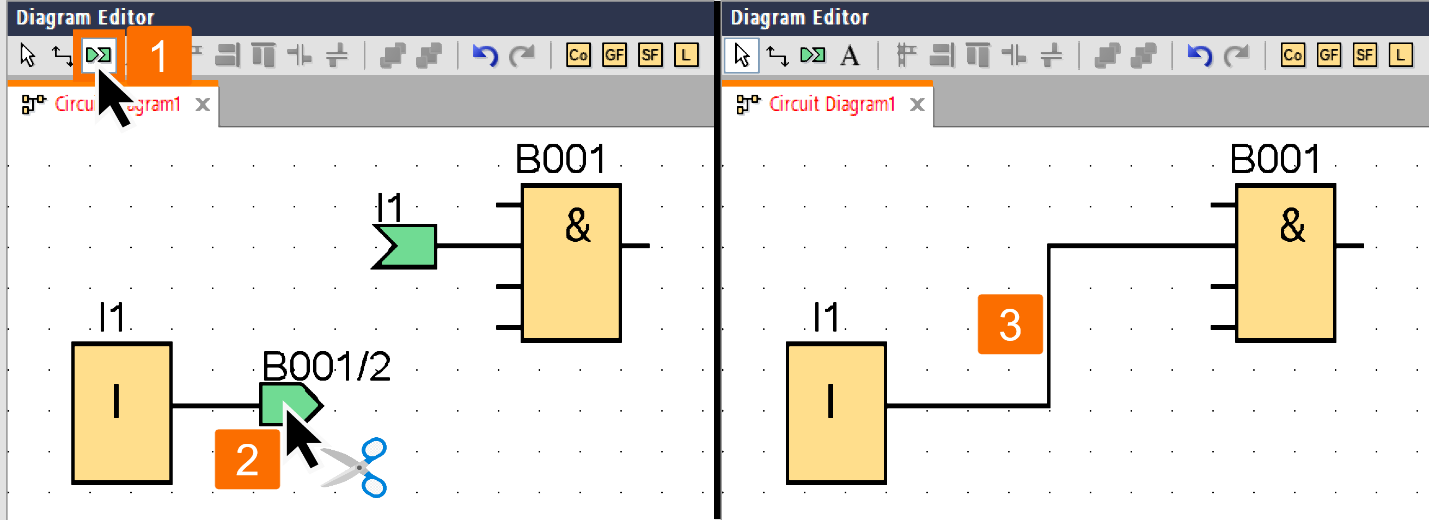
After you have activated the Cut/Join tool, choose a connection you want to split to separate the connecting line visually. It is important to note that the link between the blocks will remain intact.
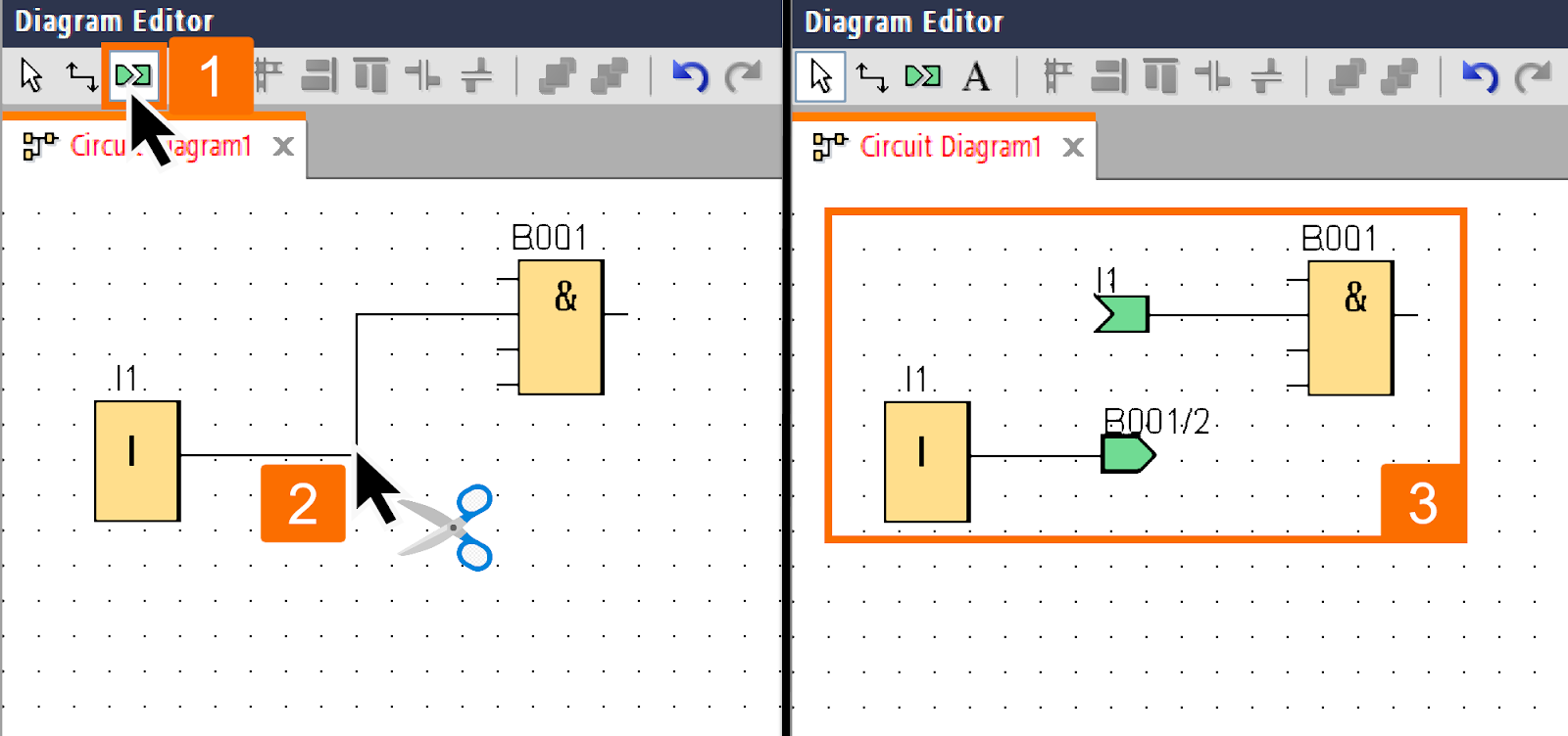
Arrowhead icons will now be displayed at the open ends of the cut connection. They serve as a visual representation of the signal flow direction. This way, users don't have to refer to the documentation or spend time figuring out signal flow direction through trial and error.
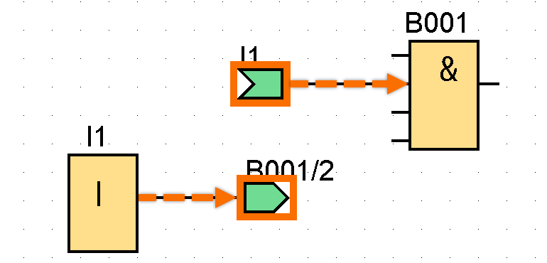
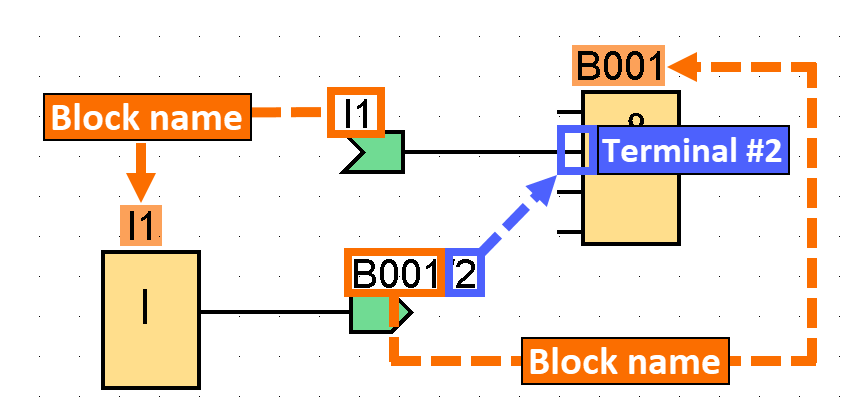
The cross-references, positioned above the icons, display significant details. It includes the circuit program's page number, the block name, and the block terminal number attached to the open link.
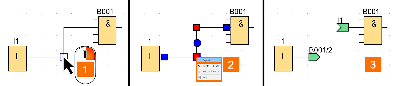
There is another way to separate the line linking the two blocks you have in mind. You can right-click over it and select the cut command from the available options.
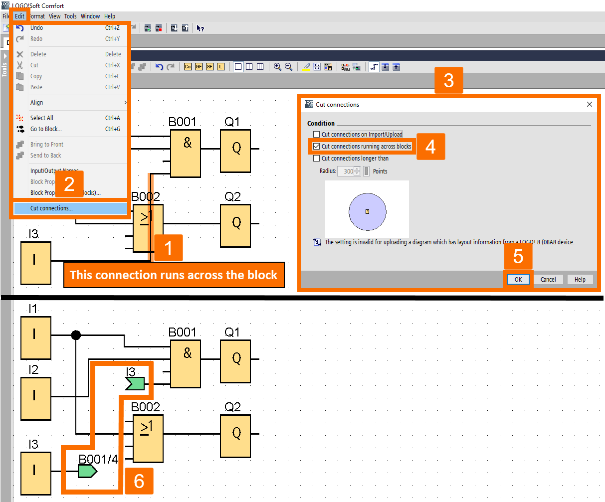
If you want to cut several connections simultaneously, use the Cut Connections command from the Edit menu. You can ensure that only the connections you want to separate are affected by setting the cutting criteria beforehand. For example, you can configure cutting all connections routed through blocks.
While the Cut/Join tool is selected, you can use a left-click on the open end of the connection to close it once again.
Another way to close your connection is to right-click on one of the open ends of the connection and select the Join command from the pop-up menu.

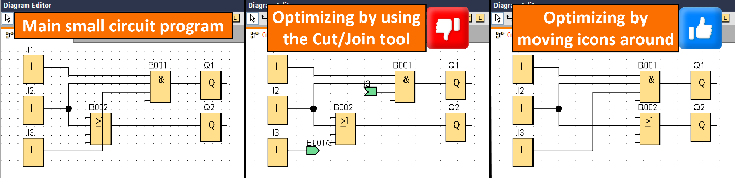
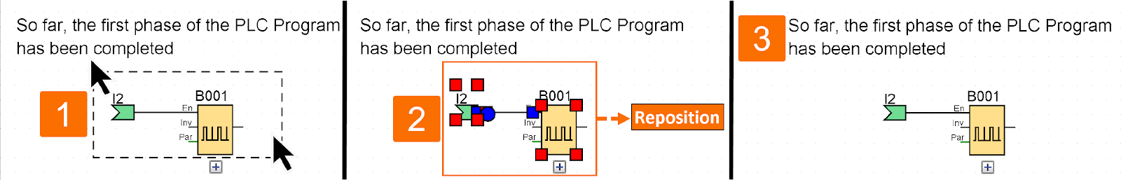
If you're working with a smaller circuit program, it's usually better to avoid using this tool for editing. Instead, try optimizing the layout by moving the icons around, which can often yield better results.
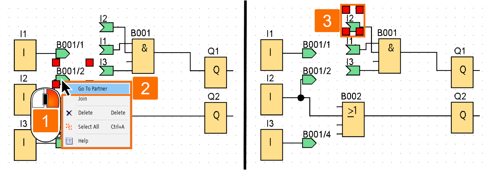
If you need to navigate to the partner end of a cut connection, you can do so quickly by right-clicking on its open end. It will bring up a shortcut menu, which includes the Go to Partner command for this purpose.
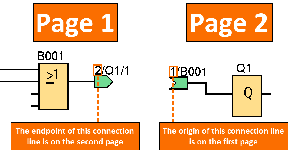
An additional benefit of the Cut/Join tool is its ability to handle circuits that continue to multiple printable pages. It includes those that traverse a page break. The lines linking the two circuit blocks depicted on separate pages are severed with no indication of cross-reference. However, using the Cut/Join tool to cut these connections has benefits. This way, a cross-reference is automatically generated, which directs to either the source or target of the connection. Thus, it allows easy tracking of the connection's origin and endpoint.
Circuit Program Documentation
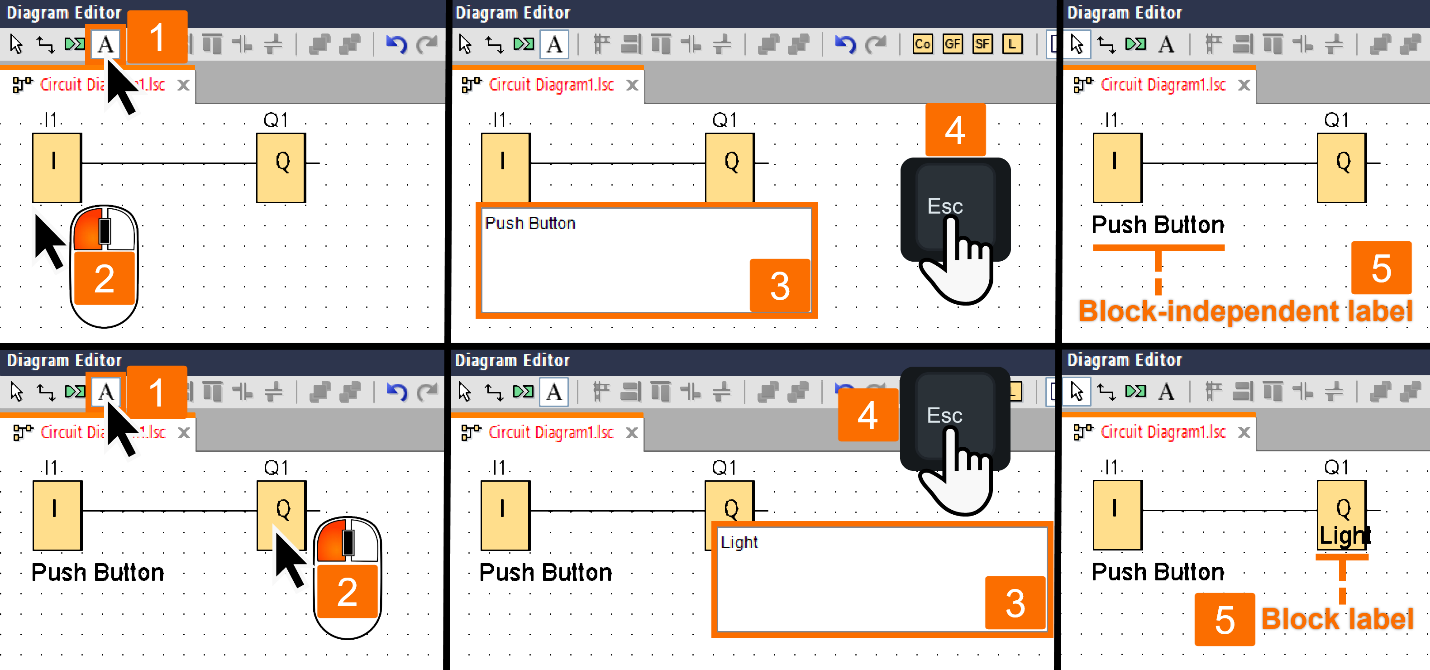
If you want to produce labels that are either block-free or block-related, you can use the text tool in the programming toolbar. To access this functionality, click on the text tool. If you have activated this icon, you can access a text input box by clicking on an unoccupied space within the programming interface or a block. After inputting the label text, you need to exit the label window. How? Click on any part of the programming interface outside the label window or just hit the ESC key. Once the window has been closed, the label text will be visible on the diagram and can be adjusted by selecting, moving, or aligning it as needed.

To modify a label, access the text tool and click on the label you wish to edit. This action will bring up the label window for editing, allowing you to make necessary changes quickly and easily.

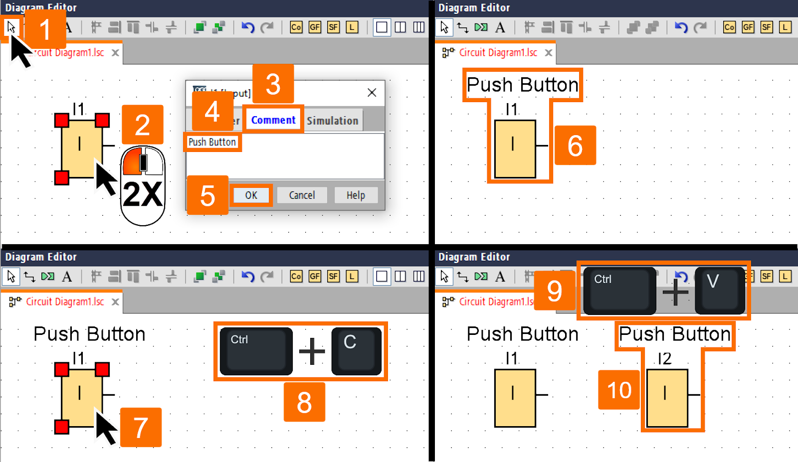
The software allows for creating block-independent labels by using the text tool and clicking on an unoccupied area. Similarly, by clicking on a block using the text tool, you can produce a label associated with the block, commonly referred to as a block comment.
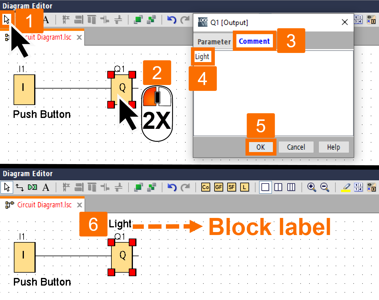
In addition to the method mentioned earlier, there is an alternative approach to creating a block comment. You can double-click on the block you want to add a comment to. It opens up the block properties window. From there, you can navigate to the Comment tab and proceed to input or modify the block comment as needed. When creating a circuit, you may find it helpful to include block comments, which can serve as a way to name blocks or describe their tasks.
If you select a block with a label attached to it, the label text will not be marked in any way. It ensures that the user can focus on the block and its associated properties without any distractions from the attached label.

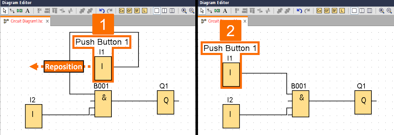
If you move a block with a label assigned to it, the label will also move along with the block and be placed in the new position. It ensures the design remains appealing and maintains a clear visual relationship between the two elements.
When you want to copy a block with an associated label, it's crucial to consider how you create the label. There are two scenarios to consider: In the first scenario, the label is created by clicking a block while the text tool is activated. If you copy the block in this scenario, only the block, not the label, will be copied to the clipboard.

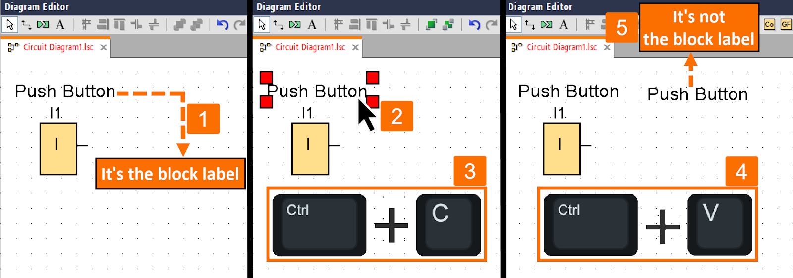
In the second scenario, the label is created using the comments tab in the properties block window. If you need to copy the block in this scenario, it will be copied to the clipboard with its associated label. When you paste the block elsewhere, the label will also be included and will be associated with the block.
Deleting the associated label of a block occurs when the block is cut. The associated label can be selected and acted upon separately to be moved, copied, cut, or pasted. Once an associated label is pasted from the clipboard, it ceases to be associated with the block.
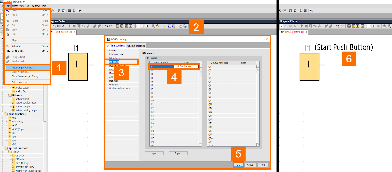
Designating block numbers and connector names for inputs and outputs can be done at once. To do so, open the Edit menu on the top toolbar and select Input/Output Names. Then in the pop-up window, select the I/O names item and assign names to desired inputs and outputs. Once you have finished, press the OK button.
Linking Comments
Text comments have the capability of being linked to either function blocks or cut connectors. When you have selected the text you wish to link to a function block, click on the yellow cube in the middle. After that, while holding down the left mouse button, move the pointer to the function block you want to link it with.
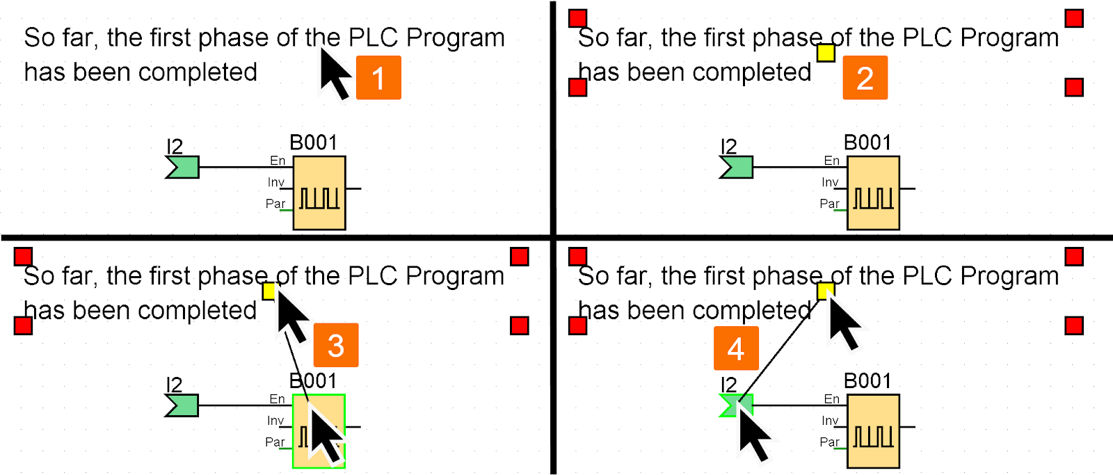
Linked comments are synchronized with the movement of the figure they are linked to. You can modify the comment's position relative to the figure using the same technique as you would for a block comment.
Conclusion
In conclusion, you learned how to clean up the connection layout using the Cut/Join tool. You learned how to split the desired connection line while keeping the link between the blocks active. Also, you found out what kind of information can be accessed through cross-references of cut connections.
You got familiar with creating block-related and block-free labels using the text tool. You grasped how to call and edit existing labels to optimize the circuit program documentation. You learned in the case of copying blocks, the method the block label was created must be considered.
Finally, you became familiar with linking text comments to function blocks or cut connectors. This way, the comments attached to a particular figure move in tandem with the movement of that figure.
