Siemens PLC Programming | An introduction to the Cause and Effect Matrix language in TIA Portal

Introduction - Siemens PLC Programming Using Cause and Effect Matrix
The IEC 61131-3 standard defines five languages that you can use to program PLCs. Each language has its own interface and its own interactions in order to meet the requirements of the different applications that you will have to develop. To diversify the tools at our disposal, Siemens has created a language aimed at simplifying programs that include a lot of conditional interactions: The Cause and Effect Matrix (CEM).
The CEM language offers a simple interface in the form of a table where each row represents a cause and columns represent effects. You can link causes to effects by specifying an action in the cell where they intersect. This makes reading programs much simpler and clearer.
This tutorial will teach you the basics of the CEM language: How to create causes, effects, and actions.
Prerequisites
To follow this tutorial, you will need an installation of TIA Portal v17 - How to Install and Get Started with Siemens TIA Portal and S7-PLCSIM. You cannot use any other version of TIA Portal. No other hardware or software is required.
CEM’s working principle
The Cause and Effect Matrix comes as a table where rows represent causes and columns represent effects. You can link one or multiple causes to one or multiple effects by adding an action in the cells where they intersect.
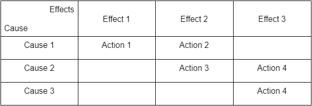
The CEM table above works as follows:
- Cause 1 is linked to Effect 1 through Action 1. It means that if Cause 1 is true, Action 1 will be applied to Effect 1.
- Causes 1 and 2 are linked to Effect 2. This means that if Cause 1 is true, Action 2 will be applied to Effect 2 OR If Cause 2 is true, Action 3 will be applied to Effect 2.
- Causes 2 and 3 are linked to effect 3 through Action 4. This means that if Cause 2 AND Cause 3 are both true, Action 4 will be applied to Effect 3. In this case, action 4 is an action group.
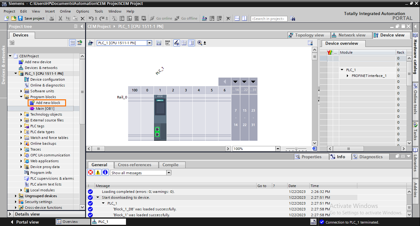
Let’s create a Cause and Effect Matrix. Open TIA Portal, and create a new project with the CPU of your choice. Then, Click on “Add new block”.
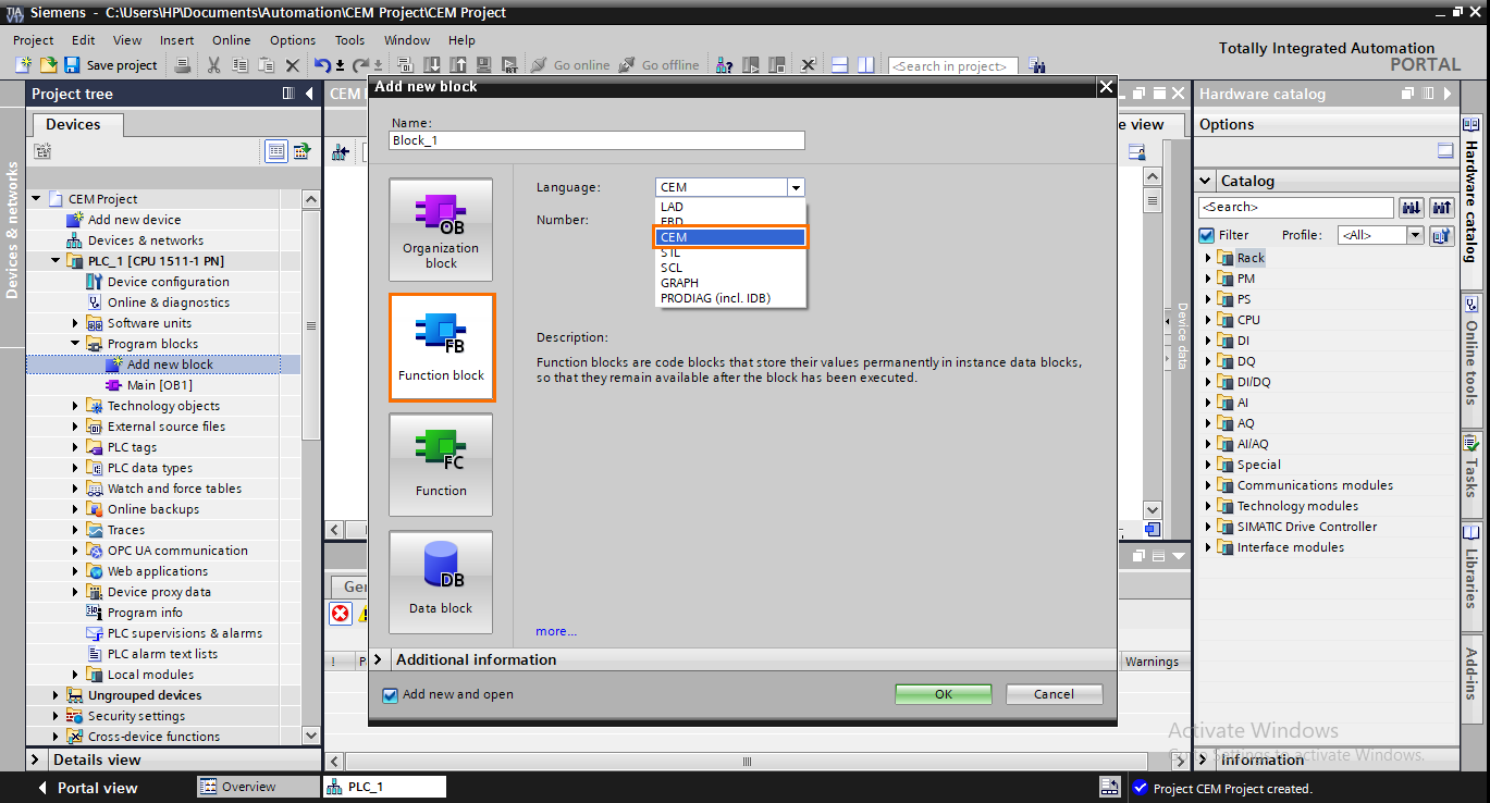
CEM can only be used in Functions Blocks (FB). You can’t use the CEM language in Organization Blocks (OB) and Functions (FC). In the “Add new block” window, Click on “Function block” and select “CEM” as language.
Once the FB is created, you should see the CEM interface appear.
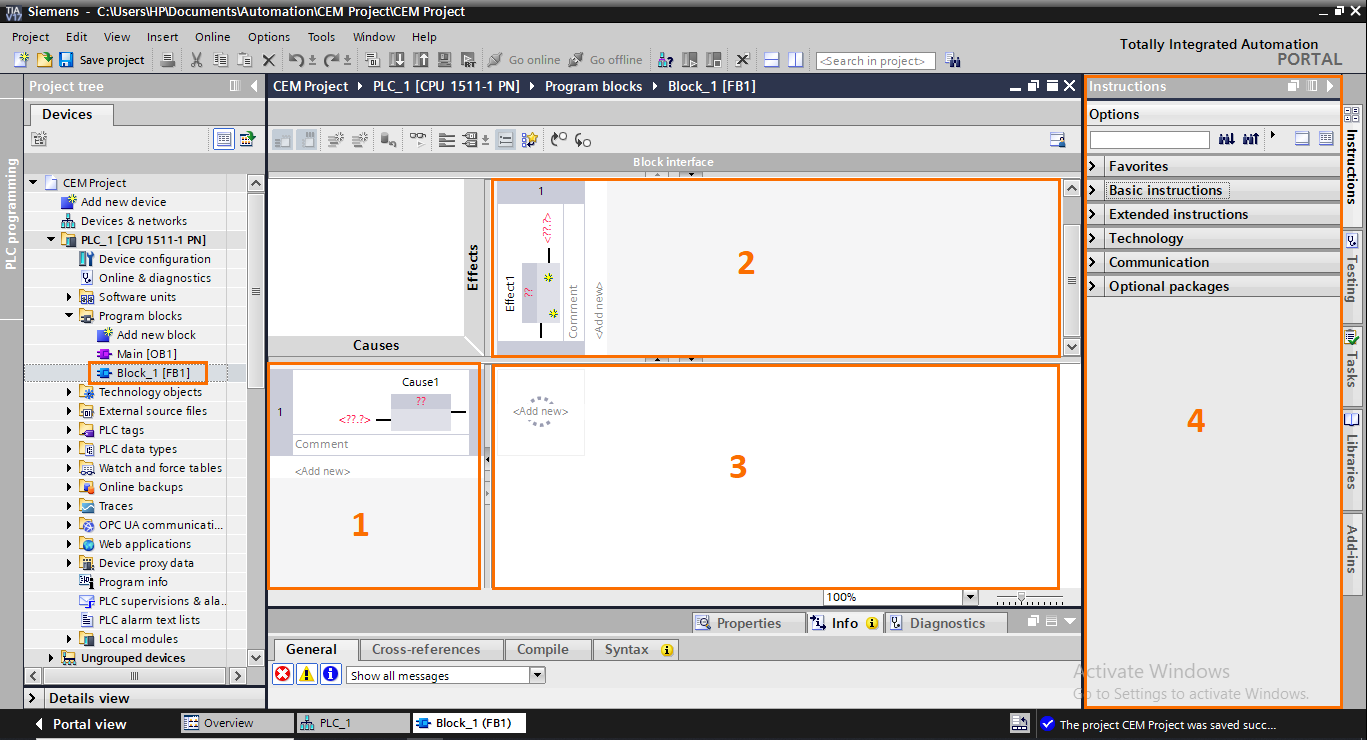
- Cause rows: This is where you can create causes. Each row represents a cause. You can create new causes by clicking on “Add new” or dragging and dropping the cause from the instructions section.
- Effect columns: This is where you can create effects. Each column represents an Effect. You can create new effects by clicking on “Add new” or by dragging and dropping the effect from the instructions section.
- Intersection actions: This is where you can create actions. Each cell can contain an action or an action group that will affect the effect column. You can create new causes by clicking on “Add new” or by dragging and dropping the cause from the instructions section.
- Instructions section: This section contains all the possible cause, effect, and action instructions you can use in CEM.
CEM’s cause types
Open the “Cause instructions’ folder in the instructions section.
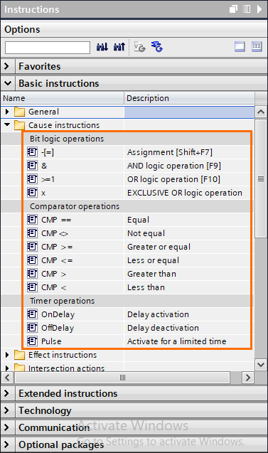
There are three types of causes you can use:
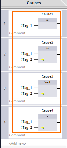
Bit Logic Operations: Contains the four simple logic operations assignment (=), AND (&), OR (>=1), and XOR (x). These instructions can only be used with boolean variables.
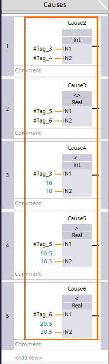
Comparator Operations: Contains all the basic comparison instructions. You can compare any type of variable except booleans.
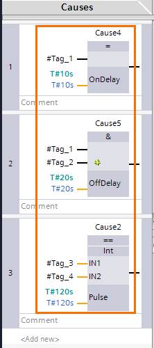
Timer Operations: Timers work a little differently. You must associate them with a bit logic or comparison instruction. The timer will be applied to its associated instruction. For example, if the result of a cause is 1, the OnDelay timer will wait for the entered time to elapse before actually setting the output of the cause to 1. The reverse is true for the OffDelay. And the Pulse timer will activate the cause output for the entered time.
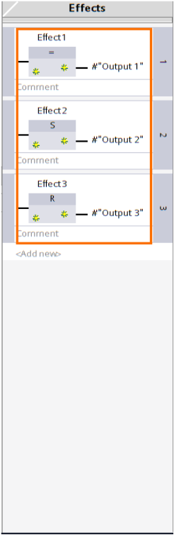
CEM's effect types
Open the “Effect instructions’ folder in the instructions section.
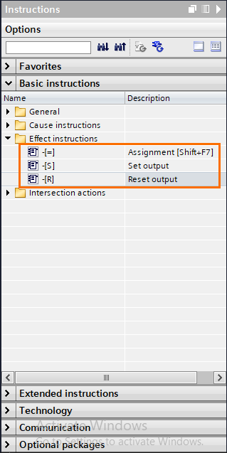
There are three instructions you can use:
- Assignment (=): If the associated action is activated, the output(s) of the effect will be set to 1. In the other case, the output(s) will be set to 0.
- Set (S): If the associated action is activated, the output(s) of the effect will be set to 1 permanently.
- Reset (R): If the associated action is activated, the output(s) of the effect will be set to 0 permanently.
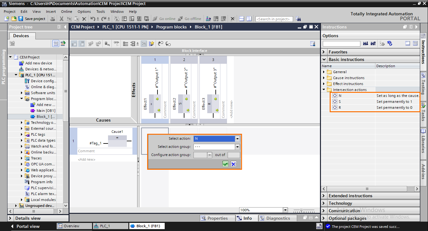
CEM's action types
There are two types of actions:
- Simple actions: Associate one cause with one effect. If the cause is true, this type of action can assign (N), set (S), or reset (R) the effect.
- Action groups: Associate multiple causes with one effect. If the selected causes are all true, this type of action can assign (N), set (S), or reset (R) the effect.
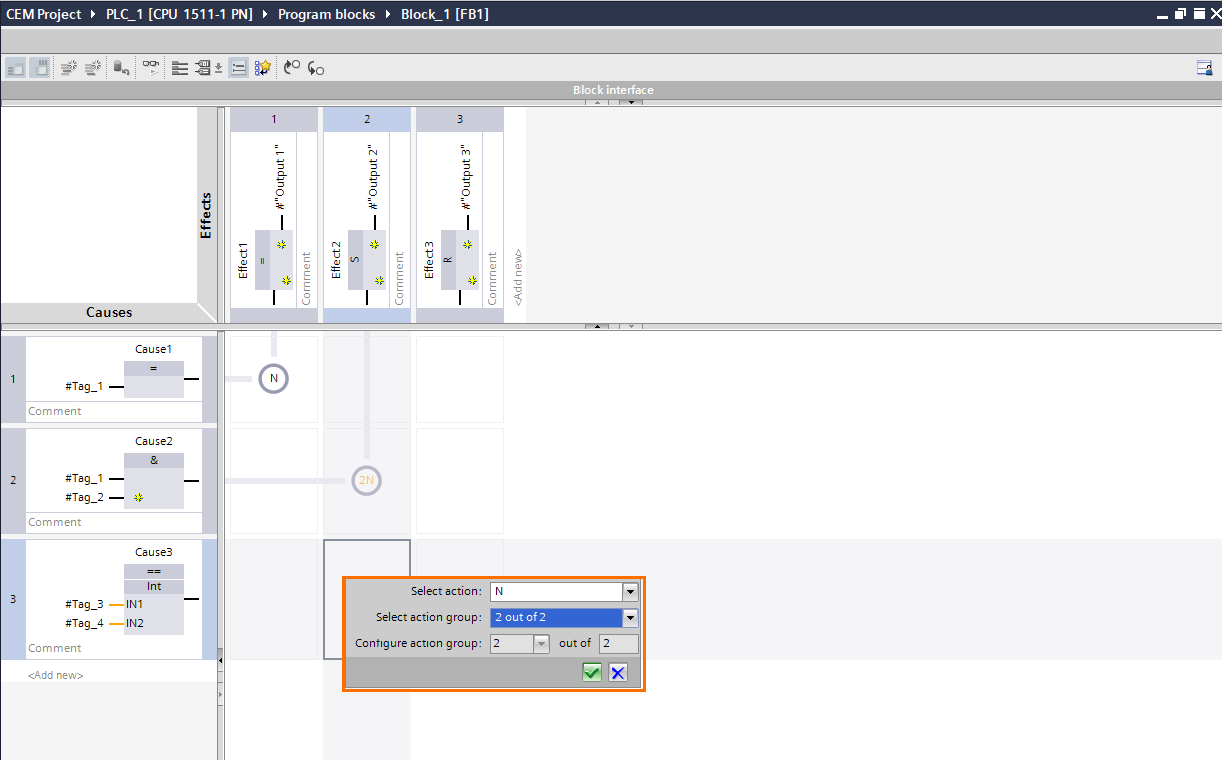
To create a simple action, drag and drop the desired instruction (N, S, or R) from the instructions section or double-click on the cell and define the type of action instruction.
To create an action group, double-click on the concerned cells and define both the action instruction and the action group. Then, in the “Configure action group” section, you can select how many causes are in the group.
First, create an action group for one of the concerned causes.
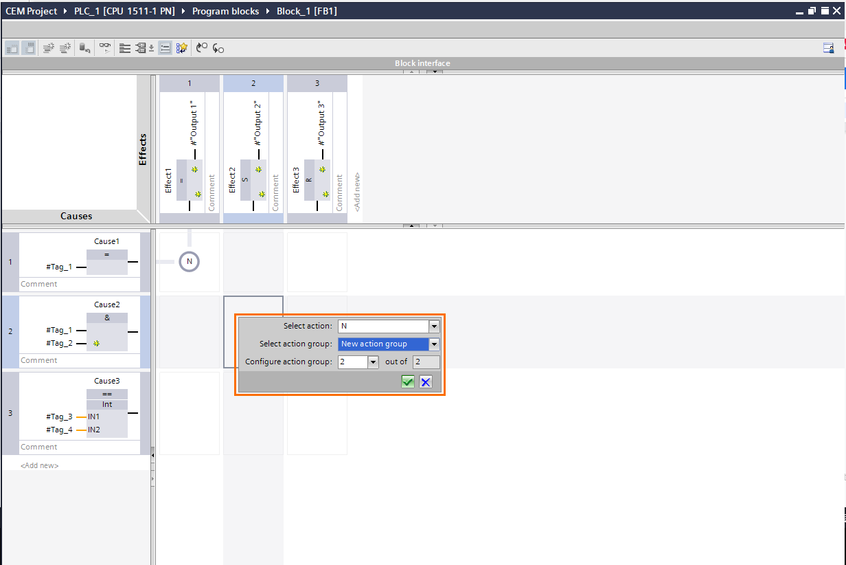
Then, for the other causes, repeat the same action but instead of creating a new group, select the one already created.
Testing a CEM program
Let’s consider the following CEM program:
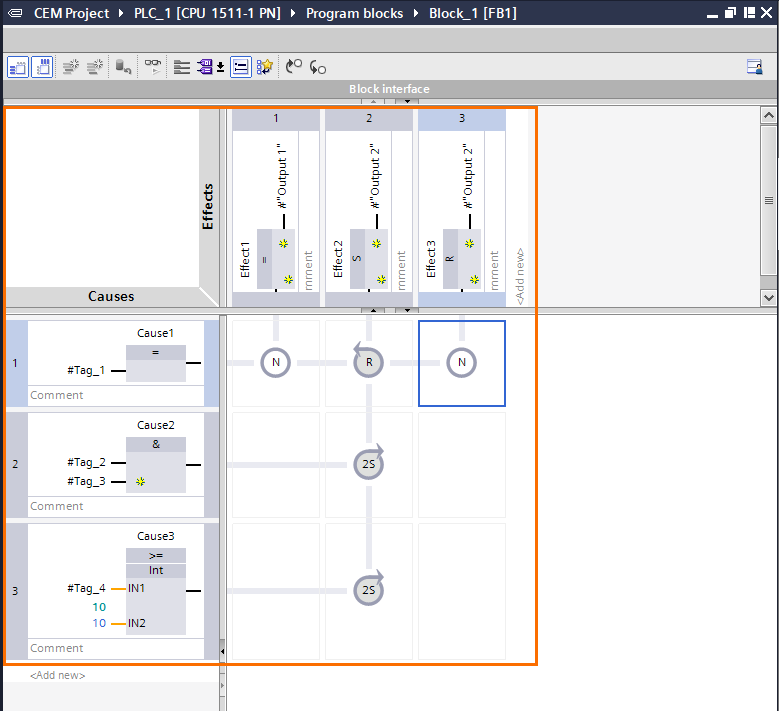
- Cause 1 assigns the state of Tag_1 to output 1. If Tag_1 is true, output 1 is set to 1. If not, it’s set to 0. Also, it has an R action to reset the 2 out of 2 set action of effect 2.
- Cause 2 and 3 are associated with a 2 out of 2 action group that sets output 2 to 1. If (Tag_2 & Tag_3) and (Tag_4 >= 10) are true, Output 2 is set permanently to 1.
- Cause 1 resets output 2. If Tag_1 is true, Output 2 is set to 0 permanently.
Then, call the CEM FB in the main program (OB1) and edit the inputs and outputs as follows:
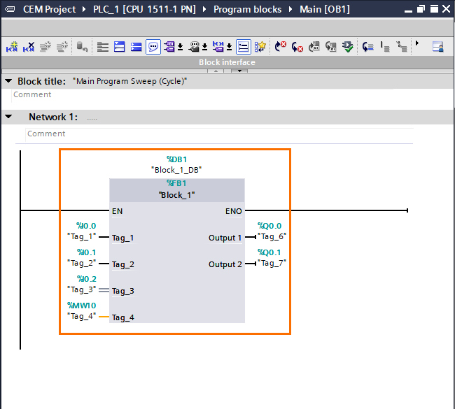
Load this program into PLCSim or an actual PLC. Once done, activate the monitoring on both the main program and the CEM block. You can use a watch table or a sim table to modify the state of the tags.
The state of cause 1 (Tag_1) is assigned to effect 1 (Assignment to Output 1) and effect 3 (Resetting Output 2).
When both Cause 2 (Tag_2 & Tag3) and Cause 3 (Tag_4 >= 10) are true, this sets the 2S action to 1 permanently. This will activate effect 2 and set Output 2 to 1 permanently.
Then, you can set Tag_1 (cause 1) to 1 to reset both the 2S action group and Output 2.
Conclusion on Cause and Effect Matrix
In this tutorial, you learned the basics of the CEM language. The main attraction that makes this language interesting is the clarity of reading. In the case of programs containing several conditional relations, it makes the reading really simple and intuitive. Greatly facilitating the handling of third-party programs or the diagnosis of faults.
Don't hesitate to use this language when you need to program tasks containing a lot of boolean or conditional logic operations. This will allow you to better navigate during the development or maintenance process.
