An Introduction to Statement List (STL) Programming in Siemens TIA Portal

Introduction
The IEC 61131-3 standard defined 5 PLC programming languages: 3 graphic languages (Ladder, Function Block Diagram, and Sequential Function Chart) and 2 text languages (Instruction List and Structured Text). The large majority of PLC manufacturers use these standard languages.
In the Siemens environment, the IL language is called STL for Statement List. It is a low-level assembly language. This means that we use instructions to control the CPU directly. Although Siemens has begun to abandon this language (for example it is not supported by the S7-1200 family and the S7-1500 family has to emulate it), it is still widely used. Especially in the older S7 families (S7-300 and S7-400). As long as they are still supported, you will inevitably come across this language during your career.
STL being a low-level language offers complete control over your program since you are manipulating data inside the processor itself. This also allows you to fully understand the operation of the PLC’s architecture.
In this tutorial, we will take a look at some of the most common STL instructions, and program a simple box sorting machine in Siemens TIA Portal.
Prerequisites
To follow along with this tutorial, you will need an installation of TIA Portal. We will be using TIA Portal v17, but you can use any other version. No other hardware or software is required.
In addition, you can refer to this Siemens Ladder Logic tutorial to fully understand the machine we will be programming in this tutorial.
Understanding the Siemens PLC architecture
Before giving any instructions to the processor, it’s important to understand how it works. In this section, we will take a look at the PLC’s inner architecture.
The CPU uses two 32-bit registers called Accumulators (the accumulator 1 being the main one). They are used to do operations over data transferred to them from any memory area. Plus a 16-bit register called Status Word (only the 9 LSB are used) where each bit indicates certain information regarding the program’s execution. The most important status bit is the RLO (Result of Logic Operations) which contains the final result of a succession of logic operations in the program (AND, OR, XOR…etc)
The memory is divided into 7 areas, each area is dedicated to one type of data. These areas are
- Input process image (I): Contains the values read by the physical inputs.
- Output process image (Q): Contains the values written in physical outputs.
- Memory area (M): Dedicated to global variables.
- Local area (L): Dedicated to local variables (exists only within an OB, FC, or FB).
- Data blocks area (D): Dedicated to Data blocks (DBs)
- Timers area (T): Dedicated to timers.
- Counters area (C): Dedicated to counters.
Each area comes as a table of bytes. A bit address is designated as:
- DataType ByteNumber.BitNumber
(For example, I 1.5 means “bit number 5 from the byte number 1 in the Input process image area).
In the case of bytes (8 bits), words (16 bits), and double words (32 bits), you have to add B, W, or D after the data type then indicate the starting byte number (For example MB1 means “Byte number 1 in the Memory area”. MW5 means “Word starting at byte 5 in the Memory area”. MD8 means “Double word starting at byte 5 in the Memory area”).
NB: Be careful of memory overlap when addressing data. For example, MW5 takes both MB5 and MB6. Using any bit from bytes 5 and 6 in another part of the program would interfere with the value written in MW5.
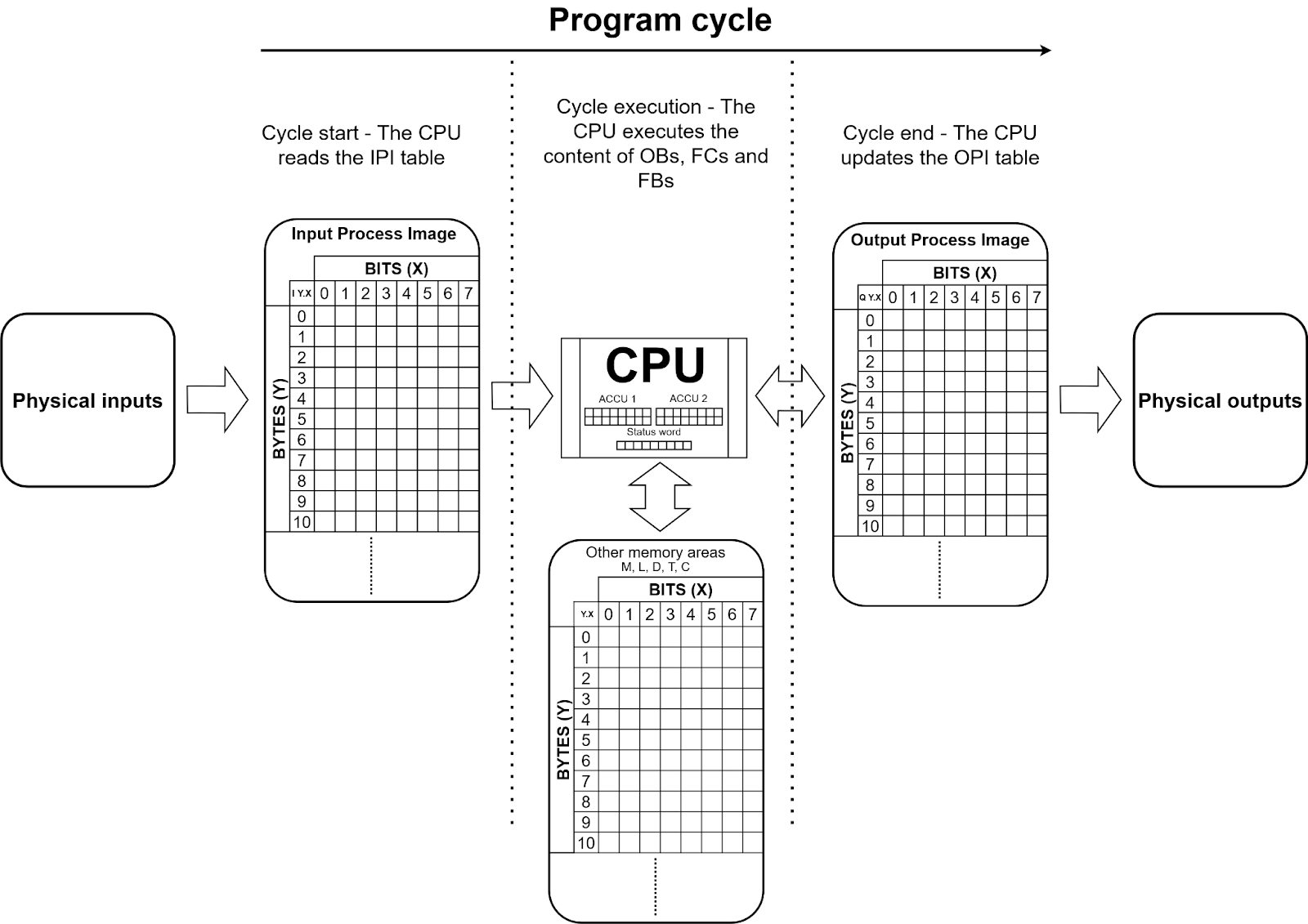
The 2 Process Image areas are a bit peculiar. They are not constantly updated in real-time. The IPI area reads the status of the physical inputs only at the start of each cycle. Then, the CPU writes all the new values calculated during the program in the OPI area which updates the physical outputs at the end of the cycle.
This means that if the value of a physical input changes during the execution it would not affect the values that the program currently processes. The values of the IPI and OPI are static during the cycle’s execution.
The next diagram sums up the global operation of a Siemens PLC.
Programming STL bit operations in TIA Portal
The STL language is a text language where you write 1 instruction per line. There are two major types of instructions :
- Conditional instructions: They are executed (or not) depending on the state of the RLO status bit.
- Unconditional instructions: They are always executed regardless of the RLO status bit.
When 1 or more boolean interrogation(s) (AND, OR, XOR…etc) are stated, the final logic result is assigned to the RLO. (For example, If “X AND Y OR Z = 1”, then the RLO is set to 1). There are conditional instructions for both states (0 or 1) of the RLO status bit.
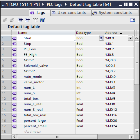
After creating a new project (with any CPU you want except an S7-1200). Open the “PLC tags” in the Project tree, double-click on “Default tag table” and define the tags shown in the next figure.
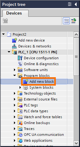
Create a new OB (Organization block) by double-clicking the “Add new block” in the Project tree.
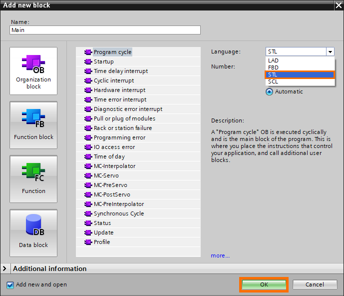
An “Add new block window” opens. Select “STL” as language and click on “OK”.
Fill in (by typing or copy-pasting) the contents of Network 1 to Network 4 as follows.
Network 1:
O "Start"
S "Auto_mode"
Network 2:
O "Stop"
R "Auto_mode"
Network 3:
O "PE_Low"
A "PE_High"
= #Large_box
Network 4:
O "PE_Low"
AN "PE_High"
= #Small_box
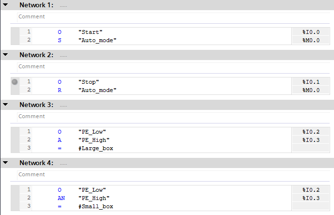
- In line 1 of Network 1 (O “Start”) we are asking the state of the “Start” bit (I 0.0).
“O” is a “OR” bit interrogation. When it is used alone, it is a simple bit interrogation, the RLO is assigned with the state of the bit we interrogate. When it comes after another bit interrogation, it forms a logic OR with it, and the result is assigned to the RLO. In this case, if the “Start” bit is at 1, the RLO is set to 1. If it is at 0, the RLO is set at 0.
- In line 2 of Network 1 (S “Auto_mode”) we set “Auto_mode” (M 0.0) to 1 if RLO = 1.
“S” is a “SET” instruction. It sets the designated bit to 1. In this case, if “Start” is at 1 (means RLO = 1), the “Auto_mode” bit is set to 1.
- In Network 2, we are doing almost the same thing as in Network 1. We interrogate the state of “Stop” but we use a reset (R) instruction on the “Auto_mode” bit.
“R” is a “RESET” instruction. It sets the designated bit to 0. In this case, if “Stop” is at 1 (means RLO = 1), the “Auto_mode” bit is set to 0.
- In Line 1 and 2 of Network 3, we do a AND logic operation (“PE_low” AND “PE_High). The final result is assigned to the RLO.
“A” is a “AND” bit interrogation. When it is used alone, it is a simple bit interrogation, the RLO is assigned with the state of the bit we interrogate (Like the “OR” instruction). When it comes after another bit interrogation, it forms a logic AND with it, and the result is assigned to the RLO. In this case, if both “PE_Low” AND “PE_High” are at 1, the RLO is set to 1. If they are at 0, the RLO is set to 0.
- In line 3 of Network 3, we assign the state of RLO to the #LargeBox local bit.
The “=” is an assignment instruction, it copies the state of RLO to the designated bit. In this case, the #LargeBox bit will be set to 1 If “PE_Low” AND “PE_High” are at 1, and it’ll be set to 0 if either “PE_Low” or “PE_High” is at 0.
- In Network 4, we are doing almost the same thing as in Network 3 but, in line 2, instead of normal “A” instruction we use an “AN” instruction to interrogate in “PE_High” is at 0.
The “AN” is a negated “AND” bit interrogation. When used alone, the RLO is set to 1 if the interrogated bit is at 0. In this case, if “PE_Low” is at 1 AND “PE_High” is at 0, the RLO is set to 1.
Programming STL jumps, timers, and counters in TIA Portal
Fill in (by typing or copy-pasting) the content of Network 5 as follows.
Network 5:
O "Auto_mode"
A #Large_box
= #Lbox_passed
JC LBOX
O "Auto_mode"
A #Small_box
= #Sbox_passed
JC SBOX
LBOX: CALL RESET_TIMER
timer_type:=IEC_TIMER
TIMER :="timerA_DB"
CALL TP , "timerA_DB"
time_type:=Time
IN :=#Lbox_passed
PT :=T#5s
Q :="Motor1"
ET :=
BE
SBOX: CALL RESET_TIMER
timer_type:=IEC_TIMER
TIMER :="timerB_DB
CALL TP , "timerB_DB"
time_type:=Time
IN :=#Lbox_passed
PT :=T#5s
Q :="Motor1"
ET :=
CALL RESET_TIMER
timer_type:=IEC_TIMER
TIMER :="timerC_DB"
CALL TON , "timerC_DB"
time_type:=Time
IN :=#Lbox_passed
PT :=T#5s
Q :="valve_motor"
ET :=
O "valve_motor"
= "Solenoid_valve"
CALL RESET_TIMER
timer_type:=IEC_TIMER
TIMER :="timerD_DB"
CALL TP , "timerD_DB"
time_type:=Time
IN :="Solenoid_valve"
PT :=T#5s
Q :="Motor2"
ET :=
BE
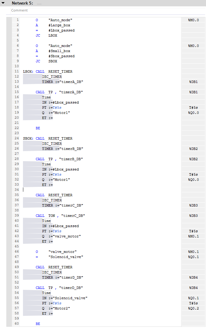
- In lines 4 and 9 of Network 5, the program jumps to the designated label if the RLO is at 1.
The “JC” is a conditional jump instruction. If the RLO is at 1, the program starts executing the instructions starting from the label associated with the jump instruction. To create a label, simply write the label name followed by “:”.
For example, If “Auto_mode” AND #Large box are at 1, the program will execute the instructions starting from the LBOX label in line 11 to the BE (Block end) instruction in line 22.
- In lines 15, 28, 39, and 53 we use the “CALL” instruction to generate “TP” and “TON” timers with their associated DBs.
The “CALL” instruction is an unconditional instruction that starts executing the called function (FC or FB). Since it is unconditional, we use jumps to execute the desired parts of the program according to the right conditions.
Using jumps is a way to turn unconditional instructions into conditional instructions!
Each time you call a function, its parameters will automatically appear. The parameters of the timer functions are:
- time_type: Time for 16 bits timer or LTime for 32 bits timer.
- IN: Boolean that activates the timer.
- PT: Timer’s duration.
- Q: Boolean set by the timer.
- ET: Current time.
- The “RESET_TIMER” function at lines 11, 24, 35, and 49 are used to reset the current time of the timers just before their generation.
To meet the machine’s requirements, we have to reset each timer before its execution. You can find more details about this in Siemens Ladder Logic tutorial.
Next, fill in (by typing or copy-pasting) the content of Network 6 as follows.
Network 6:
CALL CTU , "CounterL_DB"
value_type:=Int
CU :=#Lbox_passed
R :="Stop"
PV :=0
Q :=
CV :="num_L"
CALL CTU , "CounterS_DB"
value_type:=Int
CU :=#Sbox_passed
R :="Stop"
PV :=0
Q :=
CV :="num_S"
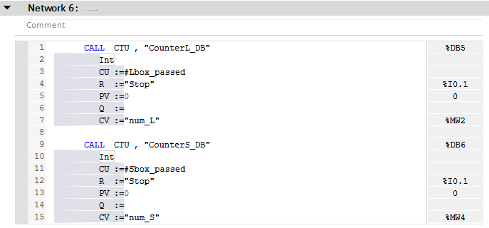
- CTU counters are called in lines 1 and 9.
Since there are no conditions regarding the generation of the counters, we simply called them in Network 6. The parameters of the CTU function are:
- value_type: Specifies the type integer used to count.
- CU: Boolean that activates increments the counter.
- R: Boolean that resets the counter.
- PV: Initial value of the counter.
- Q: Counter’s state boolean.
- CV: Counter value.
Programming STL math and data handling instructions in TIA Portal
Fill in (by typing or copy-pasting) the content of Network 7 as follows.
Network 7:
L "num_L"
L "num_S"
+I
T "total_box"
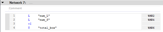
- In lines 1 and 2 of Network 7, we load the values of “num_L” and “num_S” in ACCU 1 and ACCU 2.
The “L” is a Load instruction (unconditional). It copies the value situated in the specified address into the ACCU 1. If it is used a second time successively, the first loaded value is moved to the ACCU 2 and the second loaded value is written in ACCU 1. In this case, it means that “num_L” is loaded in ACCU 2 and “num_S” in ACCU 1.
- In line 3 of Network 7, we sum the integers contained in ACCU 1 and ACCU 2.
The “+I” instruction adds the content of ACCU 2 into the content of ACCU 1 as integers. The result is stored in ACCU 1.
- In line 4 of Network 7, we transfer the content of ACCU 1 into the designated address.
The “T” is a Transfer instruction (unconditional). It transfers the content of ACCU 1 into the specified address. In this case, we transfer the content of ACCU 1 (which contains the sum of “num_L” and “num_S) into “total_box” (MW6).
Next, Fill in (by typing or copy-pasting) the content of Networks 8, 9, and 10 as follows.
Network 8:
L "num_L"
ITD
DTR
T "num_L_real"
L "num_S"
ITD
DTR
T "num_S_real"
L "total_box"
ITD
DTR
T "total_box_real"
Network 9:
L "num_L_real"
L "total_box_real"
/R
L 100.0
*R
T "percent_large"
L 100.0
L "percent_large"
-R
T "percent_small"
Network 10:
L "total_box"
L 1000
==R
R "Auto_mode"
L 0.0
T "num_L_real"
T "num_S_real"
T "total_box_real"
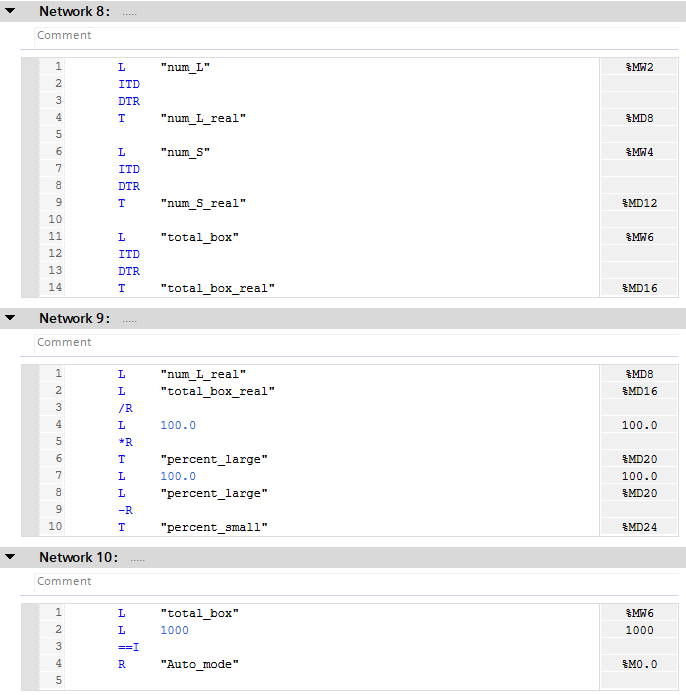
- Network 8 contains conversions of 3 integers into reals.
To convert integers into reals, we must use 2 converting instructions: The ITD instruction converts the Int in ACCU 1 into a double Int. Then the DTR instruction converts the double Int value in ACCU 1 into a real. The converted value (stored in ACCU 1) is transferred to the desired address using “T”.
- Network 9 contains math instructions to calculate percentages.
Similar to what we did in Network 7. “/R” divides ACCU 2 by ACCU 1 as reals, “+R” adds ACCU 1 and ACCU 2 as reals, and “-R” substracts ACCU 1 from ACCU 2 as reals. (The results are always stored in ACCU 1).
- In line 13 of Network 10, we do a comparison between two reals.
The “==I” checks if the integer stored in ACCU 2 is equal to the one stored in ACCU 1. If it’s true, the RLO is set to 1. In this case, If “total_box” equals 1000, the “Auto_mode” bit is set to 0.
Conclusion
In this tutorial, you learned how data are processed by the CPU using the STL language.
Although it is less clear and readable than a graphic language, STL remains a very powerful tool that allows the development of complex programs that precisely meet the requirements you want. Moreover, it provides a clearer view of the internal workings of the CPU and memory.
