Allen Bradley GuardMaster Safety Relay Wiring Tutorial

Introduction to Allen Bradley GuardMaster Safety Relays
Safety Circuits play an important role in industrial automation. Their main purpose is to protect the user from any physical harm. However, they keep the equipment from getting damaged as well. Over the years, safety circuits as well as standards evolved, became more stringent and continue to push manufacturing to the state of zero injuries.
Allen Bradley safety relays have been an industry standard for decades. A wide range of solid state as well as relay based safety circuits have been designed and sold by the company. Furthermore, safety programmable logic controllers have also been introduced to the market and are widely used in the industry. Although they are reliable, they require a lot more caution as a software mistake may cause a fatal injury. They're often used in complex applications in which distributed safety is required.
In this tutorial, we will take a look at the GuardMaster Dual Input safety relay paired with a SensaGuard safety sensor, understand the application it may be used in, the wiring scheme of both devices, and how they interact with each other.
Disclaimer
Machine Safety is a serious concern. This tutorial only provides the electrical configuration of a basic circuit. This may not be applicable in most situations. A complete system overview by a professional may be required to assess the safety requirements of any given system.
Use this tutorial as a wiring and documentation reference only.
Prerequisites & Hardware
We will be using several hardware components in this tutorial. Here are the specific part numbers of the components used as well as links to find them on eBay if you’d like to follow along.
Allen Bradley GuardMaster Safety Relay
- Part Number: 440R-D22R2
- Data Sheet: Guardmaster Safety Relays User Manual
eBay Information
- Price as of June 20th 2020: $250USD
- Purchase Here: 440R-D22R2
Allen Bradley SensaGuard non-contact switch
- Part Number: 440N-Z21S17J
- Note: you may use any variation of the SensaGuard sensor. The wiring should have the same color scheme as the one used in the video.
- Data Sheet: SensaGuard 18mm Barrel Safety Sensor Installation Instructions
eBay Information
- Price as of June 20th 2020: $250USD
- Purchase Here: 440N-Z21S17J
Allen Bradley 24VDC Power Supply
- Part Number: 1606-XLP15A
- Note: you may use any type of 24VDC power supply.
- Data Sheet: Bulletin 1606-XLE, -XLP, -XLS Switched Mode Power Supplies
eBay Information
- Price as of June 20th 2020: $250USD
- Purchase Here: 1606-XLP15A
Allen Bradley GuardMaster Selector Switch Setting
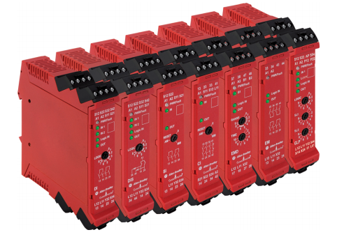
Within the GuardMaster family of relays, the user may find five distinct modules: DI, DIS, EM, EMD and SI. Each one of these modules serves a different purpose and can be used in conjunction with others to create a complete safety solution.
In this tutorial, we will be only looking at the DIS module and a simple circuit. This circuit will allow safe operation of a machine while the sensor is made and restrict operation while the sensor is not made.
The DIS Safety Relay is flexible in how it can be used in a safety circuit. The selector switch at the front of the module allows the user to select from one of the 8 modes.
- 0 | Reset Mode
- 1 | Monitored Manual - (Input 1 OR Input 2) OR Input L12
- 2 | Monitored Manual - (Input 1 AND Input 2) OR Input L12
- 3 | Monitored Manual - (Input 1 OR Input 2) AND Input L12
- 4 | Monitored Manual - (Input 1 AND Input 2) AND Input L12
- 5 | Monitored Automatic - (Input 1 OR Input 2) OR Input L12
- 6 | Monitored Automatic - (Input 1 AND Input 2) OR Input L12
- 7 | Monitored Automatic - (Input 1 OR Input 2) AND Input L12
- 8 | Monitored Automatic - (Input 1 AND Input 2) AND Input L12
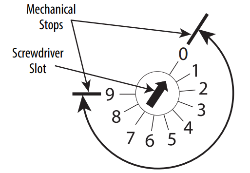
Setting the Selector Switch to the Appropriate Mode
Step 1 - Power Off the Relay by Removing Power at the A1 and A2 terminals.
Step 2 - Set the Rotary Switch to Position 0.
Step 3 - Power ON the module by applying 24VDC on A1 and A2 terminals.
Step 4 - Wait for the PWR LED to start flashing RED.
Step 5 - Set the Rotary Switch to the desired position.
Step 6 - Cycle power to the module by removing and setting back the power on A1 and A2 terminals.
Step 7 (Optional) - Record the configuration of the module on the white space at the front.
Basic Function of the DIS Safety Relay
The most basic function a safety relay must perform is to monitor a safety device and allow devices to operate when the system is safe. This can be broken down into the following three components:
- Safety Inputs
- Safety Outputs
- Reset Circuit
Safety Inputs
Safety Inputs are devices that feed into a safety relay. These components are safety switches, E-Stop push buttons, Safety Curtains and other safety relays. Proper safety devices will provide a dual redundancy circuit that will close upon proper operation and open while the system is unsafe. Dual redundancy is required for all modern safety installations as it easily eliminates the possibility of a faulty switch making the system potentially dangerous for the user.
Safety Outputs
A safety output is provided by any safety device, including safety relays, once the system is safe. As mentioned above, the safety outputs are redundant and monitor the status of the signals coming into them at all times.
Reset Circuit
A safety relay will drop outputs when the system is no longer safe. However, once the system is deemed safe by the circuit, a reset command must be issued before deeming the system safe. A reset may be automatic or manual. An automatic reset will monitor the status of inputs at all times and deem the system safe as soon as they’re all in the right state. However, in the case of a manual reset, the system will require the user to close a signal via a push button before latching in the relay and setting the outputs.
DIS Safety Relay Basic Circuit
Let’s look at the most basic circuit one can utilize the DIS Safety Relay in.
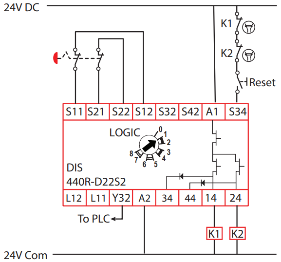
In the circuit above, we notice several things that are of importance.
Power Connections - The safety relay requires a source of 24VDC on terminals A1 and A2.
E-Stop Push Button - The safety relay provides a signal and receives one back from the E-Stop push button.
- Terminals S11 and S21 are sending a signal to the E-Stop Dual Channel Safety.
- Terminals S12 and S22 are receiving the Dual Channel safety output of the E-Stop push button.
Reset Push Button - The safety relay is wired into a “Reset” push button on terminal S34.
Output Coils K1 and K2 - The safety relay provides a dual channel output signal through the coils on terminals K1 and K2.
SensaGuard OSSD Outputs
A typical E-Stop operates on a simple open or closed principle. When the button is pressed in, the circuit is broken and the current stops flowing. Once there’s no current going into the terminals S12 and S22 of the safety relay, the system is no longer safe.
An OSSD output stands for Output Signal Switching Device. In this case, the current is created through a solid state device. By implementing the circuit in this manner, the inputs are monitored electronically and sent the same way as in the case of an E-Stop. However, such a device implements additional features that may only be achieved through such circuits.
Safety Features of the GuardMaster Safety Relays
By leveraging OSSD devices, the relay is capable of sending signals rather than on/off states. This feature allows the relay to confirm that the machine is safe much more reliably. However, this introduces a complexity in the electrical circuit. By sending various signals to the field devices, it becomes much more difficult to troubleshoot failures and malfunctions within the system.
Frequently Asked Questions
How does a safety relay work?
At a fundamental level, a two wire safety relay will measure the voltage on two channels (CH1, CH2). As long as each channel measures 24VDC, the circuit is considered safe from the relays standpoint. The 24VDC signal gets to those channels by going through different safety devices. If they're "safe," the signal passes; if they're not, the signal is blocked at the device.
What is the difference between a safety relay and a normal relay?
In a general sense, both relays will check for an input and set their status to open / closed. However, safety relays are different from normal relays in ways they handle signals. The main feature is "dual safety"; normal relays will only check a single signal while safety relays typically need to check two signals - if one fails, the relay won't be considered "safe." A safety relay is typically more sophisticated and is part of a family of "safety" devices that interact depending on the settings, part numbers, etc. Regular relays don't do more than open / close based on an input signal.
When should I use a safety relay?
Most jurisdictions dictate regulations required in industrial environment that need to be satisfied by those that run the facility. If you're involved in designing equipment that may put others at risk, you should be investigating the use of a safety relay. Furthermore, if you're unable to ensure proper de-energization of force (electrical, pneumatic, etc.), you should be using safety relays that will ensure proper operation of interlocks.
How do you test a safety relay?
Step 1 - Read the documentation. Safety relays are similar in their operation, but their settings may differ.
Step 2 - Understand which channels need to sense signals in order to be considered "safe."
Step 3 - Wire up the safety relay in a closed loop and ensure that the relay is "safe."
Step 4 - Verify the contacts of the safety outputs; if the relay is in the "safe" state, these contacts should close.
If they don't, the relay contacts, or the circuit are damaged.
What causes a relay to fail?
There are mechanical and solid-state relays. Mechanical relays will fail much faster than their solid-state. What causes a relay to fail is the number of times it opens and closes; every manufacturer will specify an average number of cycles a relay will go through before experiencing issues. Keep in mind that it may seem like a good idea to use solid-state relays everywhere. However, they can typically switch much smaller loads (lower currents).
Conclusion
The GuardMaster line of safety relays from Allen Bradley is an excellent way to implement safety in manufacturing. The user may choose from five distinct safety relays, each one providing a different functionality for the circuit.
By implementing the circuit above using a single safety sensor, it's possible to create a safety state that can be tied to VFDs, servo motors and other devices that will be utilized to safely stop machinery.
Remember that machine safety requires a professional audit of the equipment in order to determine which devices will be needed to completely eliminate hazards. Use the information above as reference only.
