An Introduction to Siemens’ legacy HMI programming using WinCC Flexible

Introduction
This tutorial builds on the knowledge gained from the previous SIMATIC Manager introduction and SIMATIC programming tutorials. Here, we will cover the second essential software for programming Siemens’ legacy industrial equipment. Unlike TIA Portal which includes PLC and HMI programming in a single environment, these two parts were separated into two distinct software; SIMATIC Manager (also called Step 7) for programming PLCs and WinCC Flexible for programming HMI panels. We will focus on the configuration and programming of HMI using WinCC Flexible.
WinCC Flexible is a vital software tool used for programming and configuring Siemens's legacy HMI panels such as the popular OP and TP series. You can create graphical interfaces that interact with your PLC programs and monitor them. These interfaces play a crucial role in industrial automation, allowing operators to interact with and control machinery.
In this tutorial, you will learn how to set up a new project in WinCC Flexible and gain insights into its interface components. We will guide you through the process of integrating your HMI project into a PLC project in SIMATIC Manager, essential for seamless communication between the HMI and PLC. Additionally, we'll cover configuring connection settings and defining HMI tags, which are crucial for effective communication with the PLC. Finally, we'll dive into the HMI programming aspect, where you will learn to create buttons and animations to design a dashboard for controlling and monitoring your industrial processes.
Prerequisites
To follow this tutorial, you will need an installation of SIMATIC Manager (Step 7) and WinCC Flexible. Here, we will be using versions 5.6 and 2008 SP5 respectively. No additional hardware or software is required.
Creating a new project and interface overview
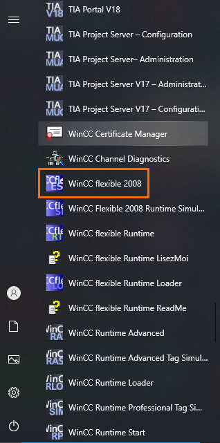
Let’s start by creating a new WinCC Flexible project. First, open WinCC Flexible from your start menu.
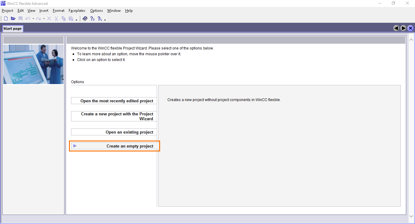
Once done, WinCC flexible will open. Before breaking down the interface, we need to create a new project first. Click on “Create an empty project.”
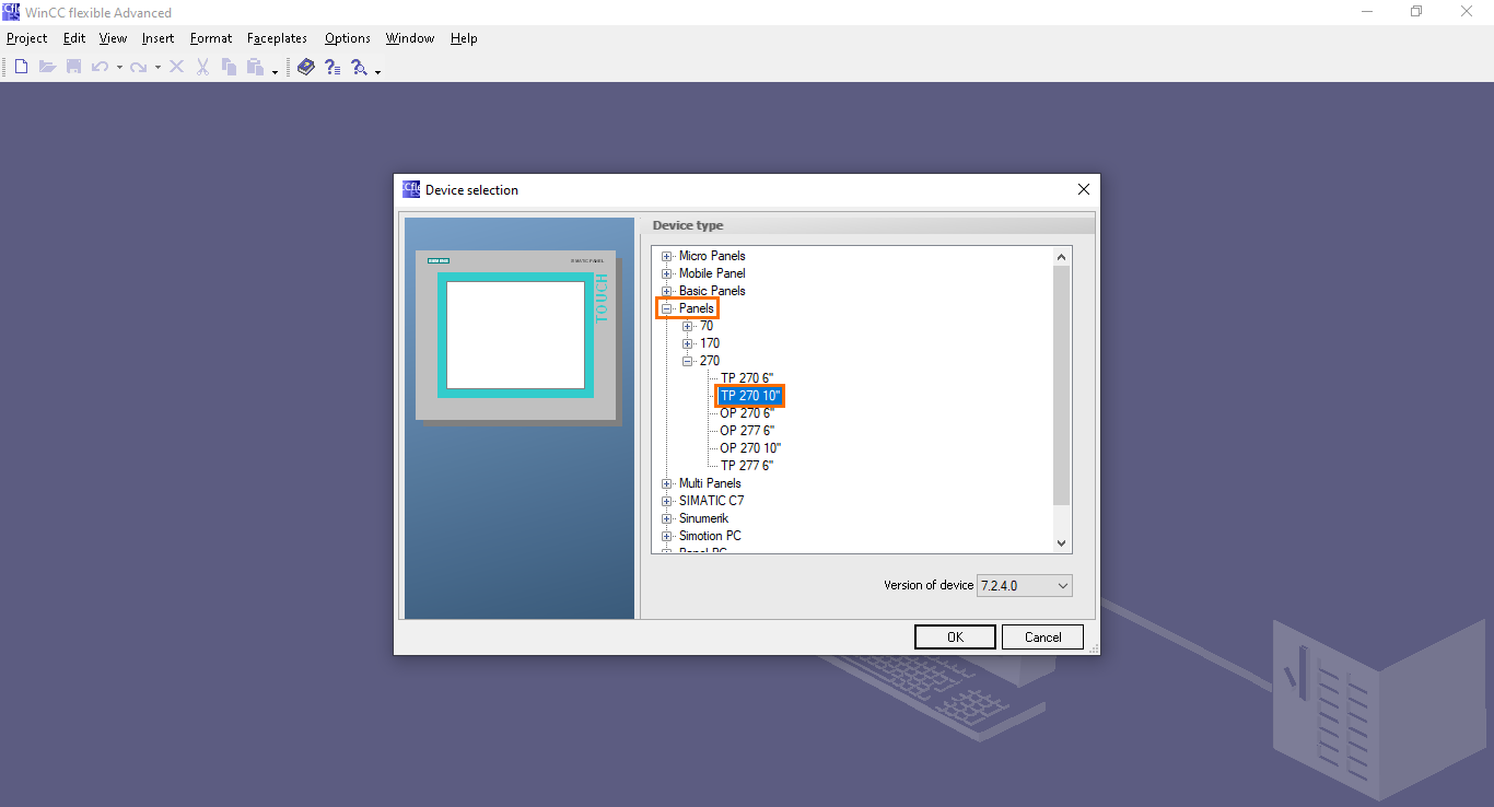
Next, you will arrive at a window where you must select the model the HMI model you will use in your project.

For this example, we will use a TP 270 10” panel which is one of the most popular HMIs. Open the “Panels” section, then select “TP 270 10” in the “270” section.
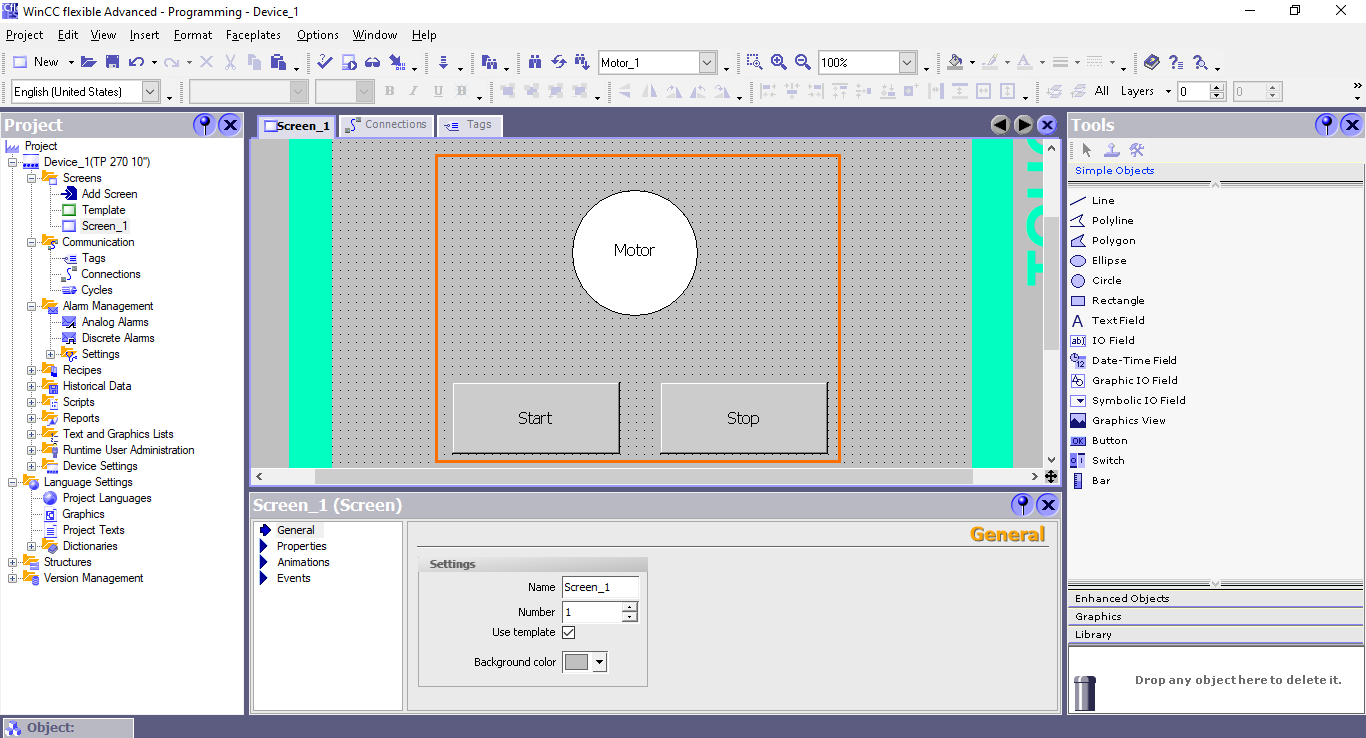
Once done, we arrive at WinCC Flexible’s main interface. Here, you can configure your HMI panel and program it.

The interface is organized as follows:
- Projet tree: here, you can find all the components of your project and access them.
- Workspace: This space represents the panel screen where you can assemble objects to form your HMI program.
- Objects and tools: Here, you can find all the objects and tools that you can use during programming.
- Properties view: Upon selecting an object, its properties will appear in this view.
Integrating to SIMATIC Manager (Step 7)
The first thing we need to perform is to associate this HMI project with a PLC project in SIMATIC Manager. For this, we will integrate this WinCC Flexible project into the project we created in the SIMATIC Manager programming tutorial.
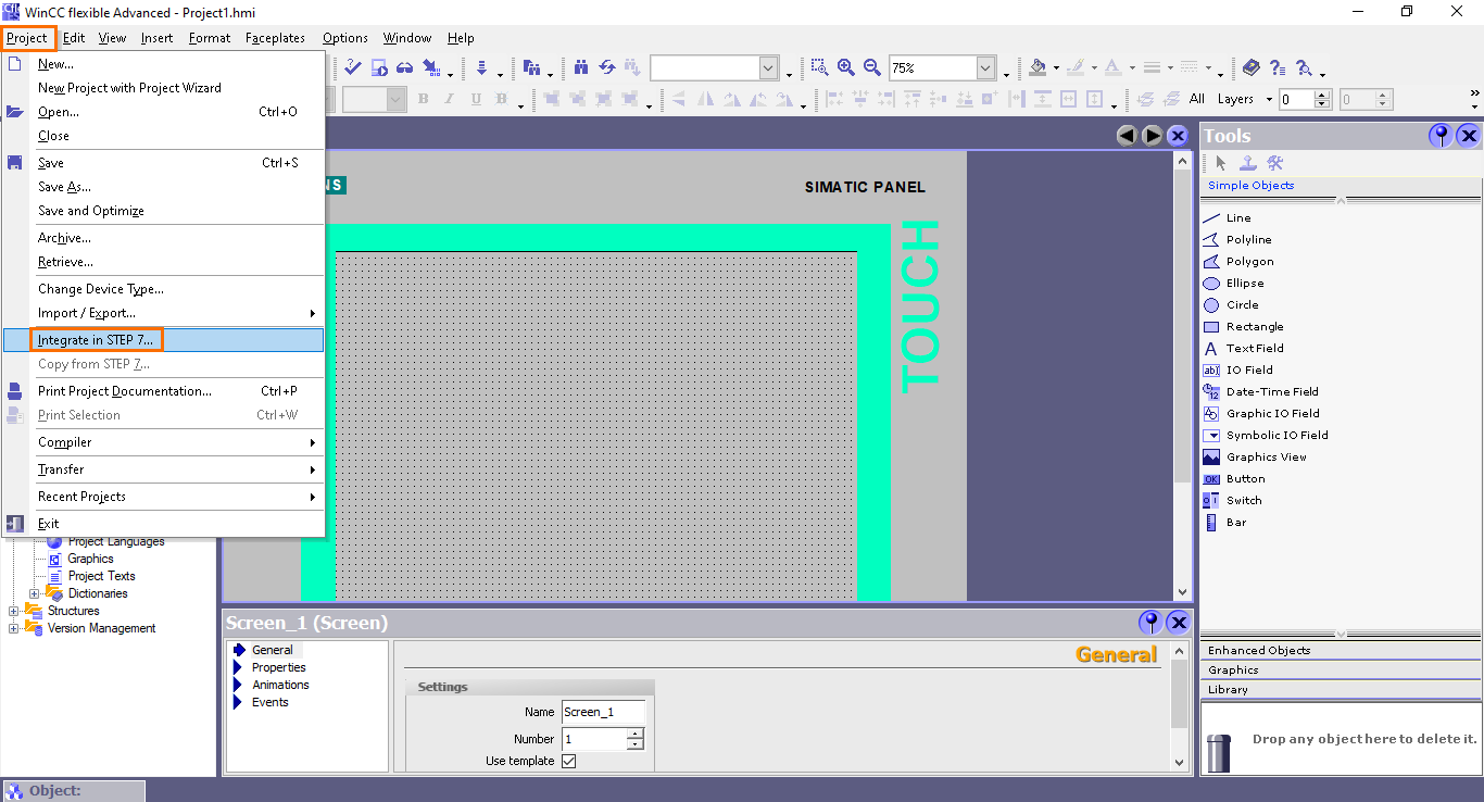
Go to the “Project” menu of WinCC Flexible and click on “Integrate in STEP 7.”
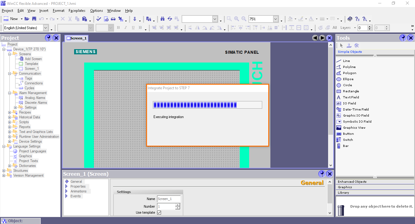
This will open a small window where all your SIMATIC Manager projects are displayed. Here, we will select the “Programming” project.

Wait for the integration to complete.
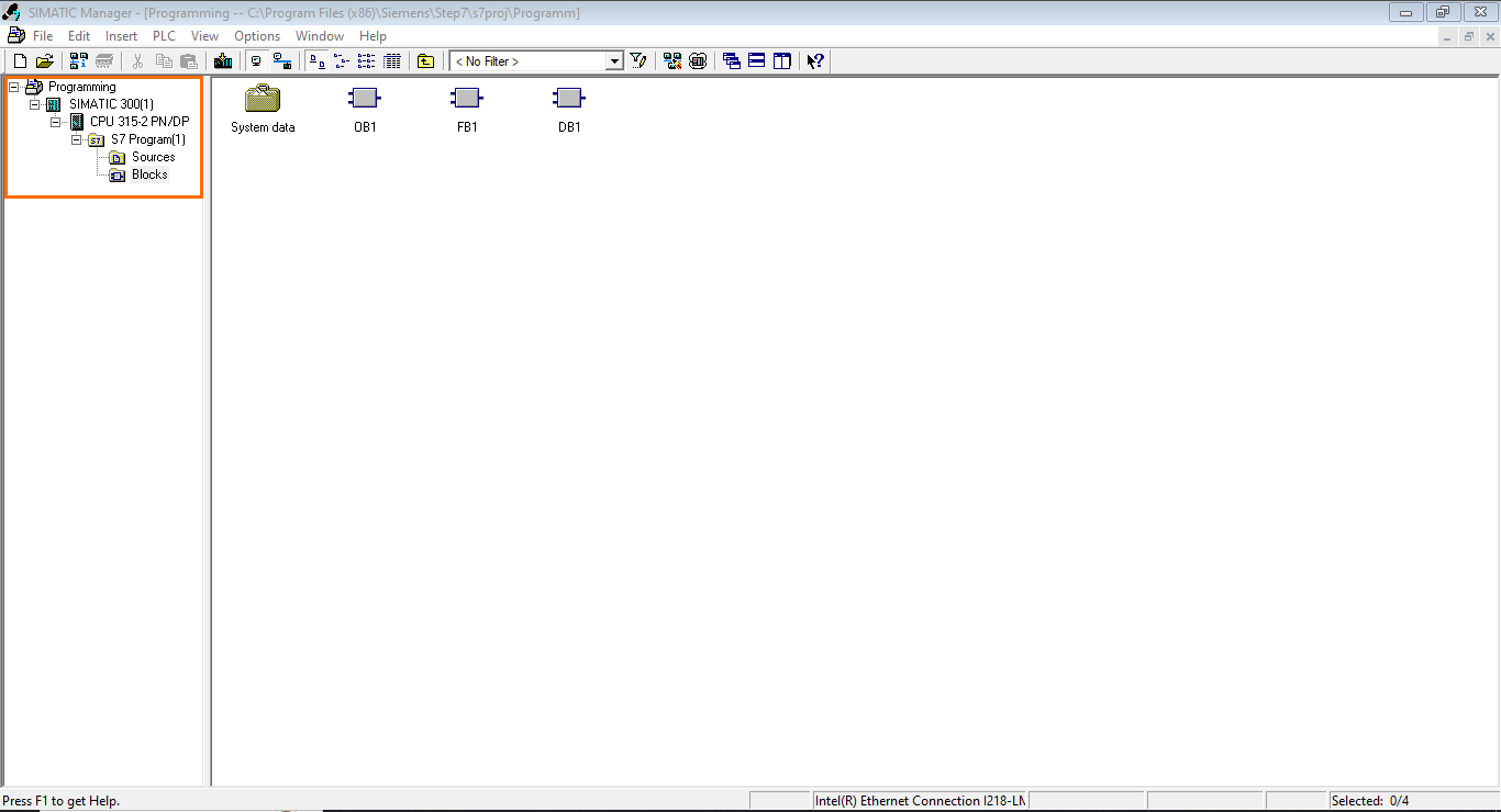
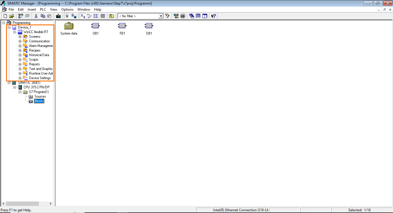
If you open the SMATIC Manager project, you will find a new section in the project tree dedicated to the HMI.
Connection settings
Now that we integrated the projects, we need to configure the connection between the HMI and the PLC. For this, open the “Connections” section in the project tree.

Here, you can define the network connections between this HMI and other devices.

Double-click on the first row to create a new connection. Since we are communicating with an S7-PLC, be sure to have “SIMATIC S7 300/400” selected in the “Communication driver” section. Also, enter the address of the target PLC station you want to communicate with. Here, the address is set at “2.” You can refer to the SIMATIC Manager introduction tutorial for more information on how to set the network address of the PLC.

Defining HMI tags
Before we can start programming the HMI application, we need to define the tags (Variables) that will be used in our program. Since we are working with a motor control PLC program, we will need three boolean tags: one to start the motor, one to stop the motor, and the last to control the motor.
Open the “Tags” section in the project tree.

To create a new tag, click on the first row of the list. This will automatically create a default tag that you can edit.

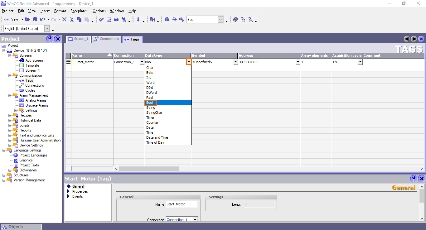
First, edit the name of the tag and set it to “Start_button.”
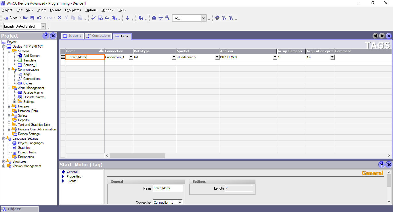
After that, set the data type to “Bool.”
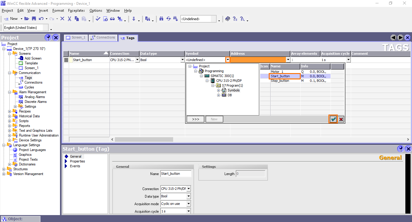
After that, we need to link it to a SIMATIC Manager Symbol (See the SIMATIC Manager programming tutorial). Open the “Symbol” by clicking on the arrow button, browse to the S7 Program Symbols, and select the “Start_buton” tag.
Once done, repeat these operations to create a “Stop_button” tag.
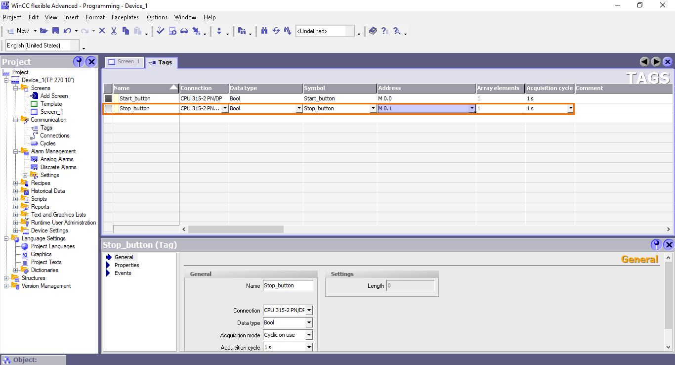
Repeat them once again to create a “Motor” tag.

HMI Programming
We have finished all the configuration to be done upstream, we can move on to programming. In this section, we will assemble blocks such as buttons and animated figures to design a dashboard that will allow us to interact with the PLC program and monitor it.

For this application, we will use two buttons to turn on and off the motor and a colored circle to indicate the motor’s state.

Buttons and events
Let’s first add a button. Select a button element and drag it to the workspace.
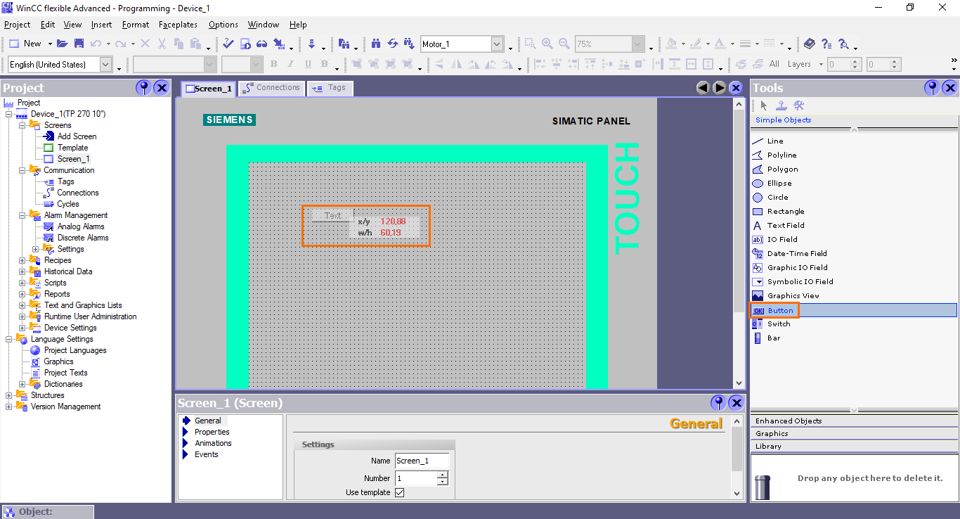
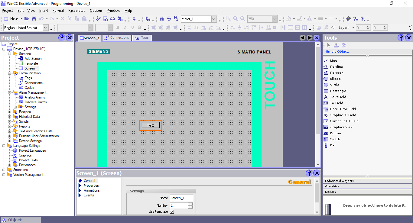
Once done, a simple button will appear where you dropped the element.
After that, you can make the button bigger by selecting it and dragging one of the corner points in the direction you want.
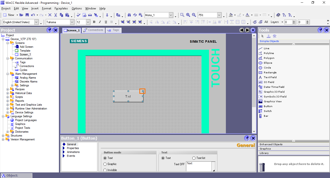
While the button is selected, its properties will appear in the properties view below. Here you can configure the appearance and behavior of the button.
We will first change the text on the button. Open the General section and click on the “Text OFF” text box.
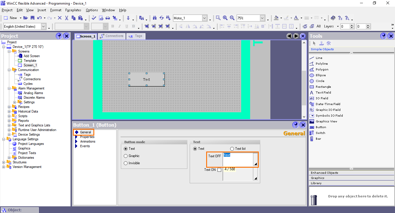
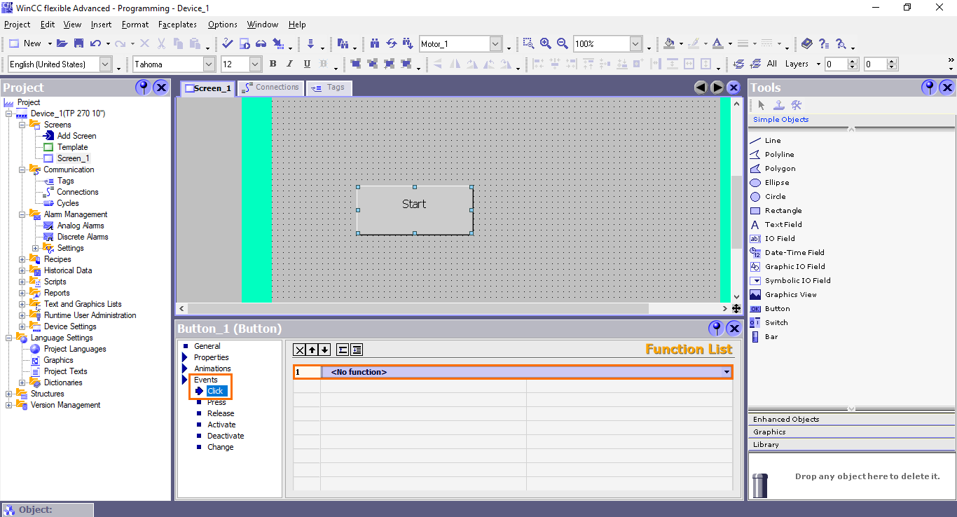
This button will be used to start the motor. Therefore, type “Start” in the text box.

Next, we need to configure the events that will be triggered by pressing the button. Open the Events section. Here, you will the different types of events available. The event type we need to use is the “Click” which triggers the event when clicking on the button. Once done, you will find the function list where you can define the function that will be executed when triggering the event.
Open the Function list by clicking on the small arrow button. Here, you will find all the different types of functions that can be used. Since we are handling boolean variables in our PLC program, we are going to focus on the “Edit bits” functions.

Open the “Edit bits” section and select the “SetBit” functions.
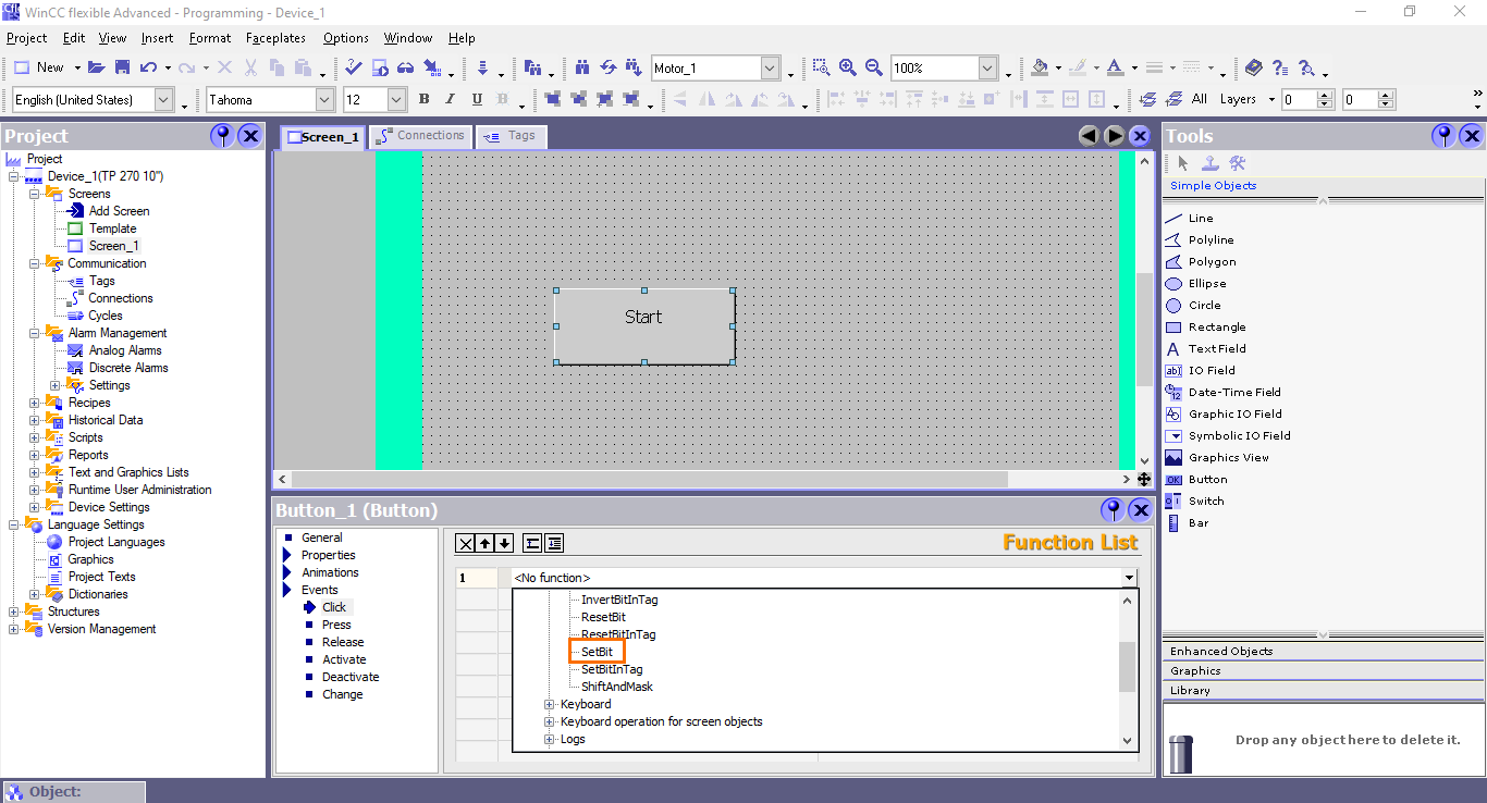
The “SetBit” function is used to set to 1 a boolean tag (variable). It will be used to set the “Start_button” to 1 upon clicking on the button.
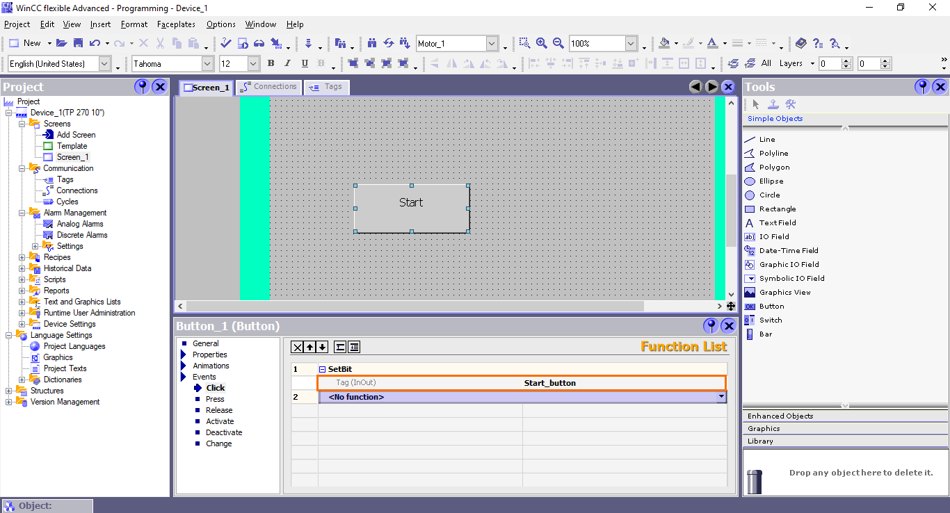
Once done, the “SetBit” function is created. We need now to define the tag (variable) associated with this function. By default, no tag is selected.

To select a tag, click on the small arrow button. This will open a list of all the available tags. Since we are configuring the Start button, we must select the “Start_button” tag.

And we are done configuring the “SetBit” event.
Since we are going to create a second button for stopping the motor, we need to add a second event function that will prevent any conflict between the two buttons. For this, we have to add a “ResetBit” function that will set the tag used in the stop button to 0. This way, both tags cannot be at 1 simultaneously. Repeat the steps for creating an event function to create a "ReseBit" function associated with the "Stop_button" tag.
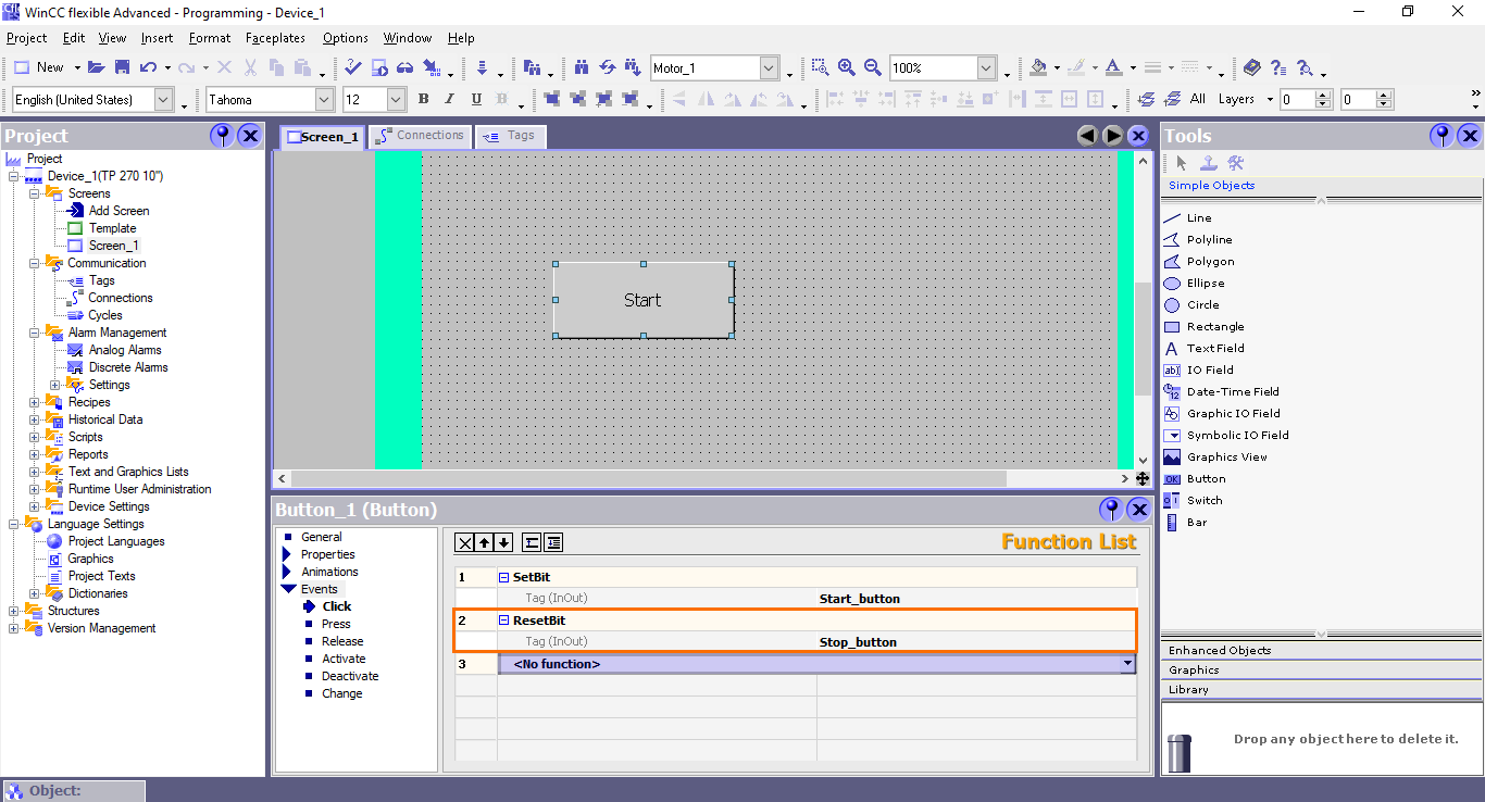
After that, repeat all the button creation steps to create a Stop button and configure its events as shown in the following figure.

The principle of this button is the same as the Start button with the exception that the tags used in the events are inverted: The “SetBit” event sets the “Stop_button” tag to 1 and the “ResetBit” event sets the “Start_button” tag to 0.
Animations
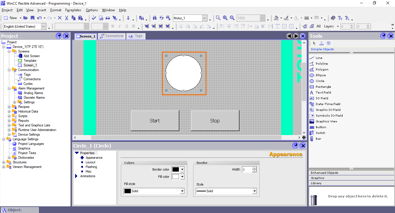
We are done creating and configuring the buttons. Now, in this section of the tutorial, we will create an animated object that will indicate the state of the motor. For this, we will use a circle shape whose color will change depending on the motor state: Green for on and red for off.
First, add a circle object in your workspace.

Once done, make the circle bigger using its corner points.
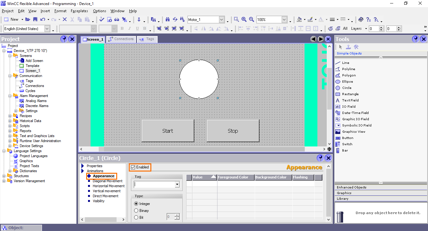
After that, in the properties view, open the “Appearance” section. Here, you can configure various animations regarding the object’s appearance. First, we have to enable the appearance animations. Click on the “Enable” checkbox.
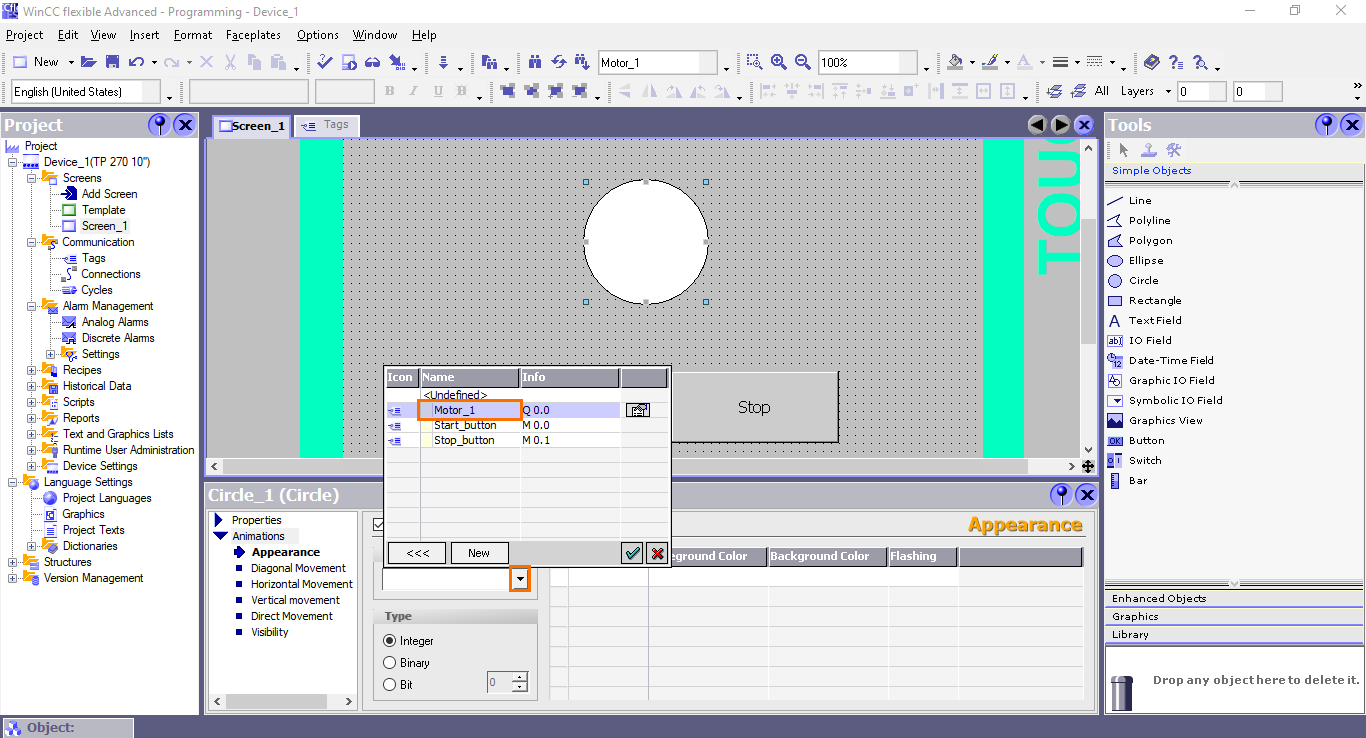
Then, we need to define the tag that will control the animation. Here, it will be the “Motor_1” tag that controls the motor. Click on the small arrow button in the “Tag” section. This will open a list of all the available tags. Select the “Motor_1” tag.
Once done, a new value will appear. By default, it is set to the 0 - 100 interval using the integer type. Since we are going to use a boolean tag, we need to use the “Bit” type. In the type section, select the “Bit.”
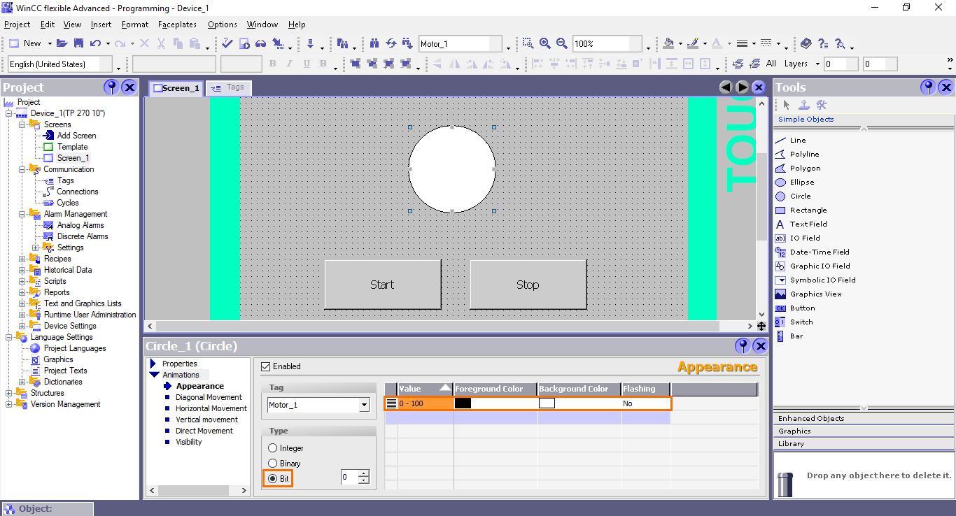
After that, click on the “Value” section and change it to 0. This value will be used for the case where the motor is off (Motor_1 tag = 0).
To indicate that the motor is off, we will change the circle’s color to red. Open the “Background Color” section and select the red color.
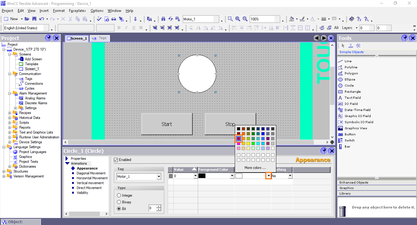
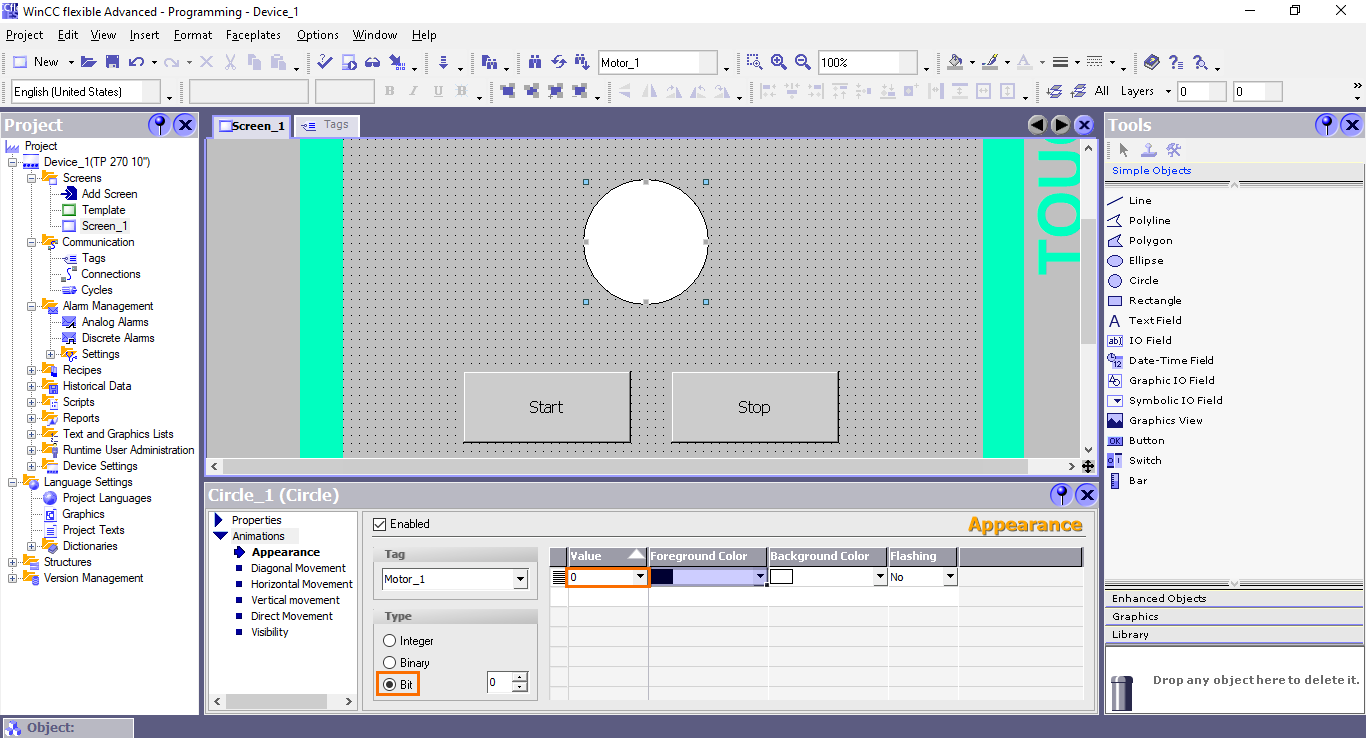
With this configuration, when the motor is off, the circle will become red.

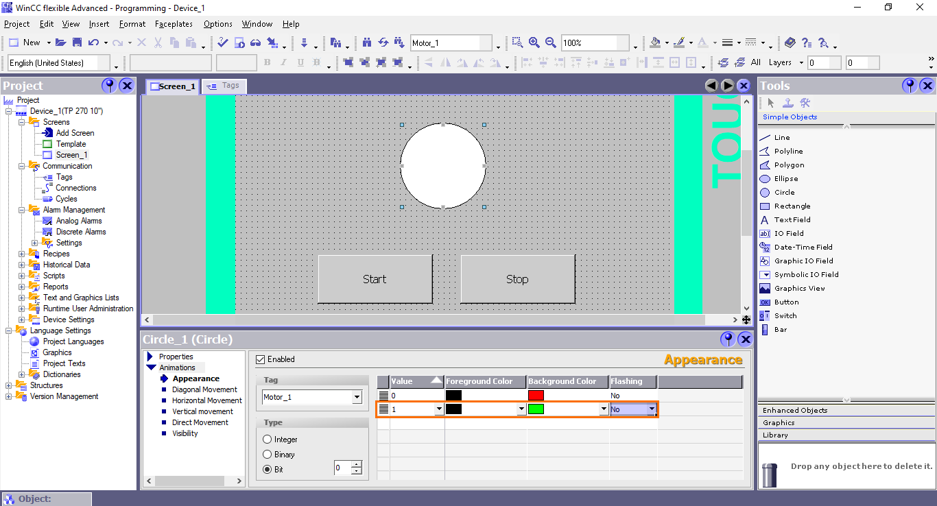
Now, create a new value equal to 1 and use the green color as the background. This way, the circle will become green when the motor is on.
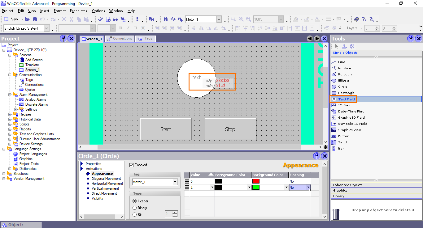
To indicate that the circle represents the motor’s state, we can add a text label with “Motor” written on it. To do this, grab a “TextField” element and drag it to the circle.
Open the “General” section of the TextField properties and type “Motor” in the “Text” field.
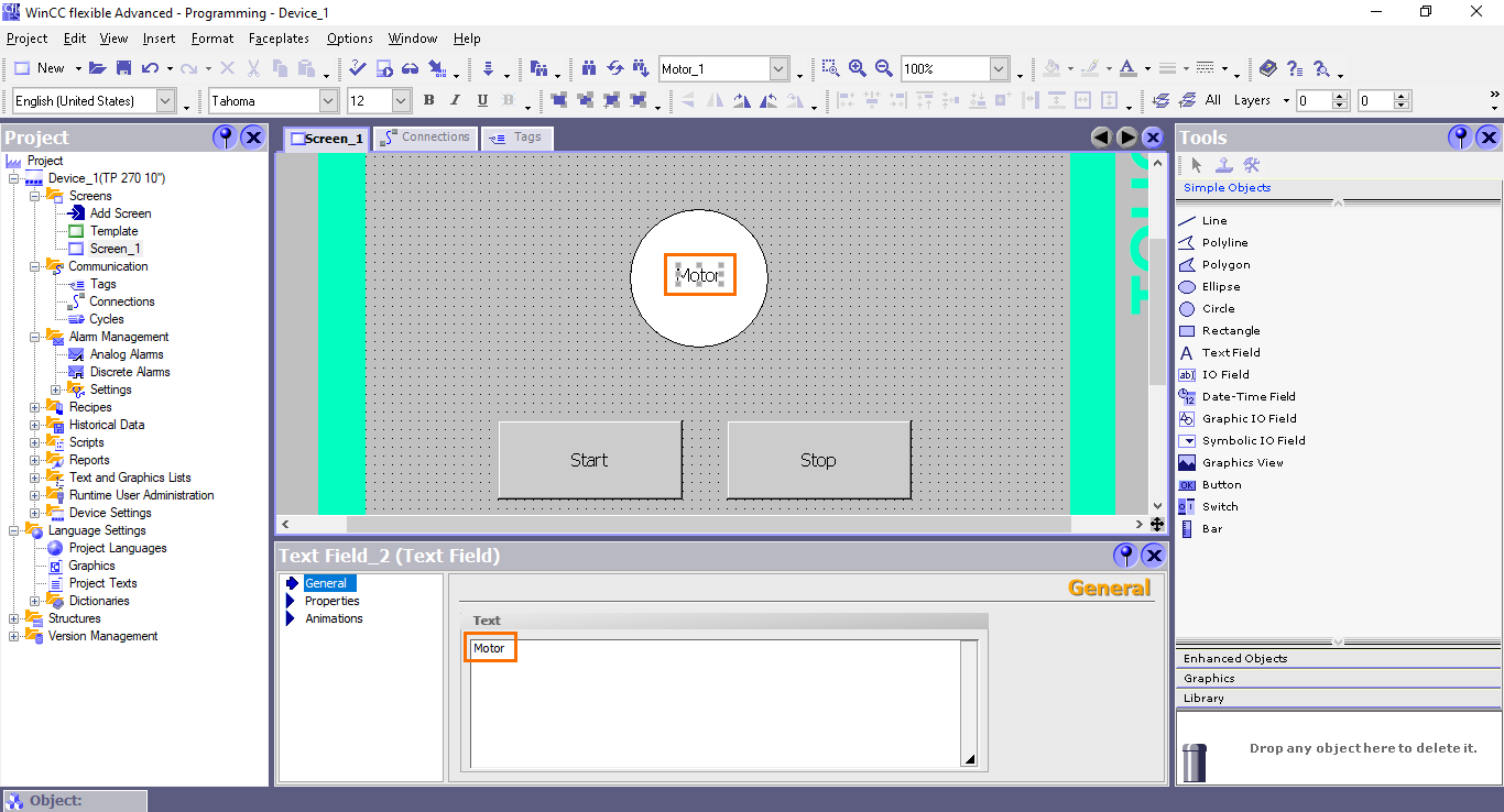
And we are done programming. This dashboard will allow us to interact with the PLC’s motor control application. We can turn on and off the motor the “Start” and “Stop” buttons. And the state of the motor will be indicated using the “Motor” circle’s colors.
Conclusion
In this tutorial, you learned how to navigate and program Siemens's legacy Human-Machine Interfaces (HMIs) using WinCC Flexible. We began by creating a new project, gaining insights into the software's interface, and understanding its essential components. Next, we integrated our HMI project into the SIMATIC Manager, ensuring a seamless connection between the HMI and PLC systems. We then explored the crucial process of configuring connection settings and defining HMI tags, setting the foundation for effective HMI programming. Finally, we delved into the art of programming an interactive HMI dashboard, enabling you to control industrial processes and monitor real-time data.
Moving forward, the next crucial step in the HMI program development is to thoroughly test your application using simulation. Simulation allows you to validate the functionality of your HMI interface without the risk of disrupting real-world industrial processes. Simulating HMI is possible within WinCC Flexible. It is also possible to make it communicate with a simulated PLC using PLCSim. Both of these subjects will be covered in the Simulating Siemens’ legacy PLCs and HMIs tutorial.
