S7-300/400 PLC programming using Siemens’ SIMATIC Manager (Step 7)

Introduction
This tutorial builds on the SIMATIC Manager Introduction tutorial. If you're just starting with SIMATIC Manager, we recommend reviewing the introductory tutorial for essential background information on project setup, hardware configuration, and block types.
In SIMATIC Manager, programming is a critical aspect of controlling industrial processes. It involves designing logical sequences that govern the behavior of hardware components. We will create a small motor control application using the LADDER language within a Function Block (FB1), which will be called in the main cyclic Organization Block (OB1).
In this tutorial, you will learn how to create a project, configure hardware components, and program a motor control application using the LADDER language in SIMATIC Manager. We will start by setting up the project and configuring a S7 300 station. Next, we will dive into the details of LADDER programming within a Function Block (FB1), covering the creation of logical sequences and variable assignments. You will also discover how to call the Function Block within the main cyclic program (OB1). To enhance program clarity, we will explore using a Symbol table, allowing you to associate symbolic names with physical input and output addresses.
Prerequisites
To follow this tutorial, you will need an installation of SIMATIC Manager (Step 7). Here, we will be using the version 5.6. No additional hardware or software is required.
Also, knowledge of the LADDER language would be preferable.
Project Setup
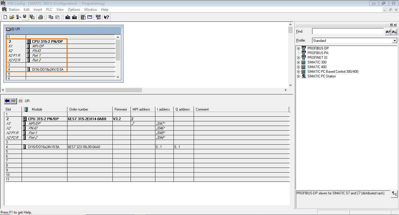
Let’s start by creating a project and configuring a S7 300 station, as shown in the following figure.
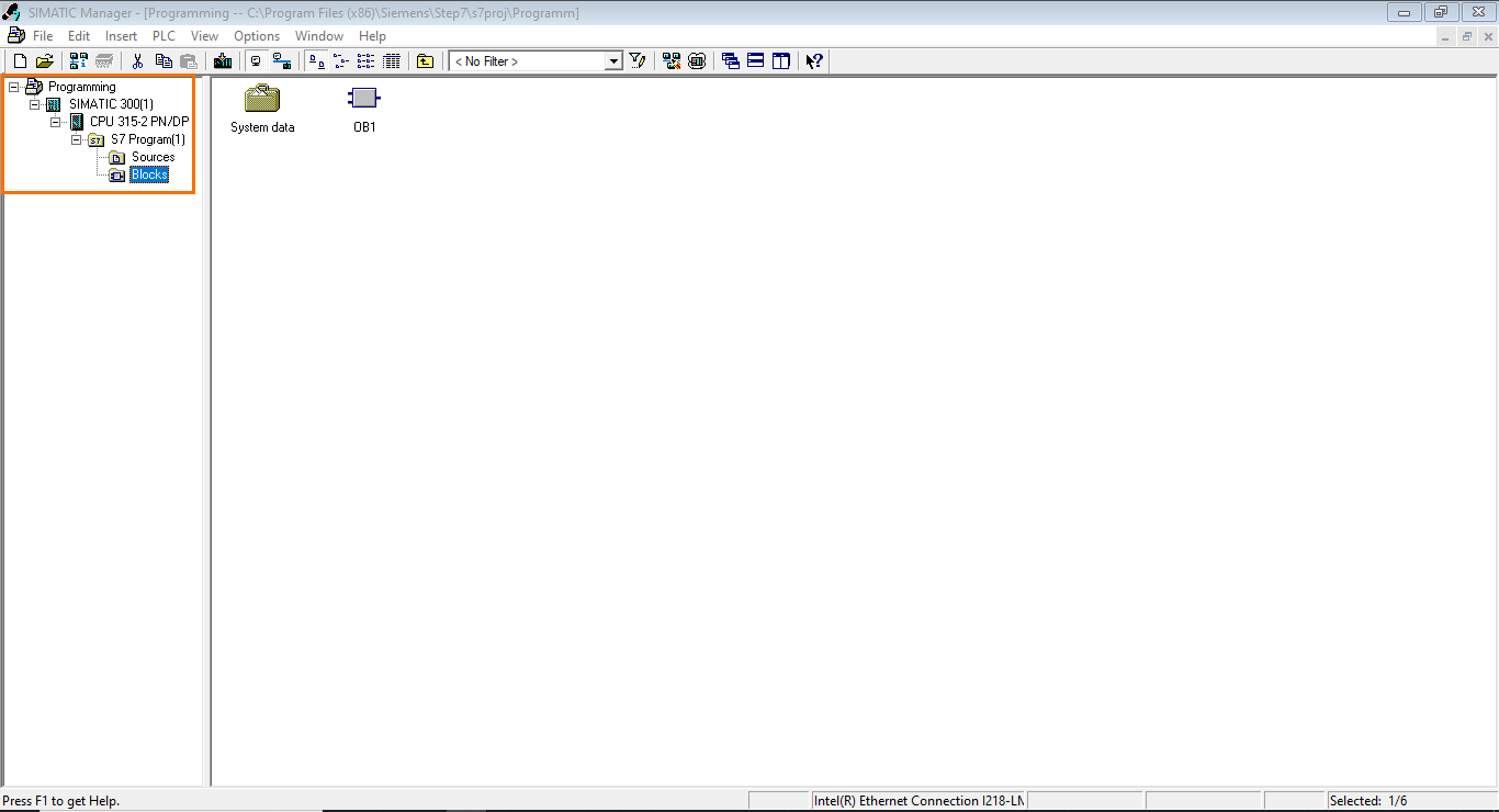
We are using 315-2 PN/DP CPU and a 16*DI/DO module on the hardware configuration side.
Note: You can find more information about the project creation, hardware configuration, and block types in the SIMATIC Manager introduction tutorial.
We will program a small motor control application using the LADDER language for this tutorial. The program will be done in a Function Block (FB1), which will be called the main cyclic Organization Block (OB1).
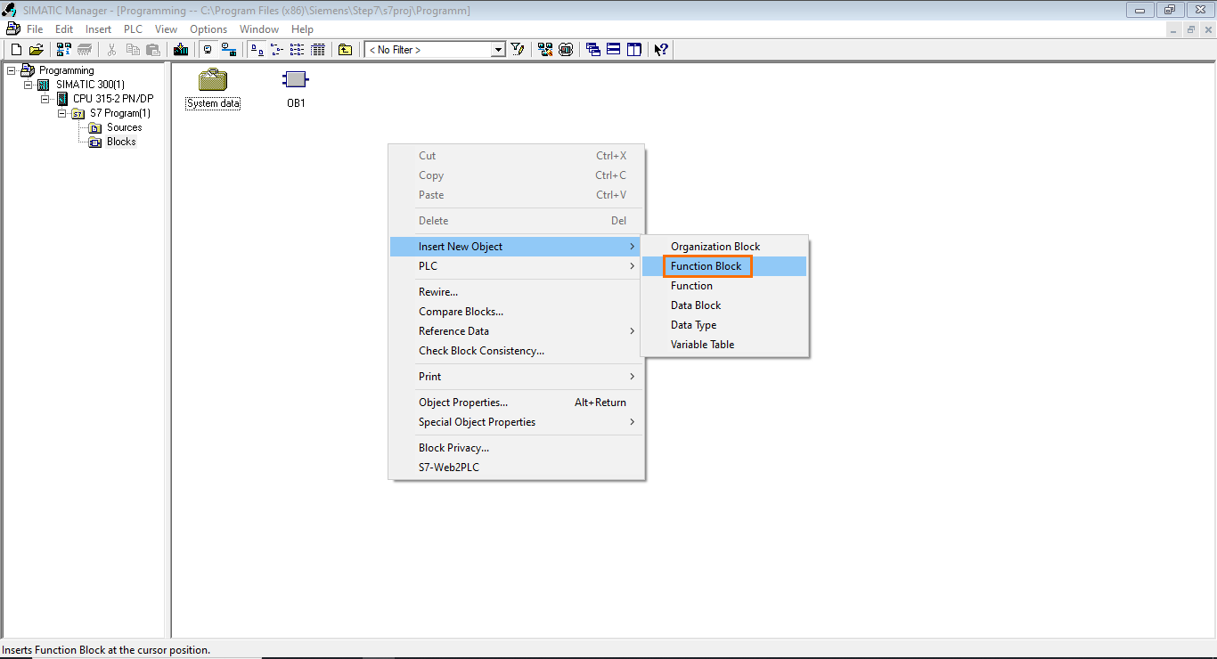
Let’s create a new Function Block (FB1). To do this, right-click in the workspace, go to “Insert new Object,” and select “Function Block.”
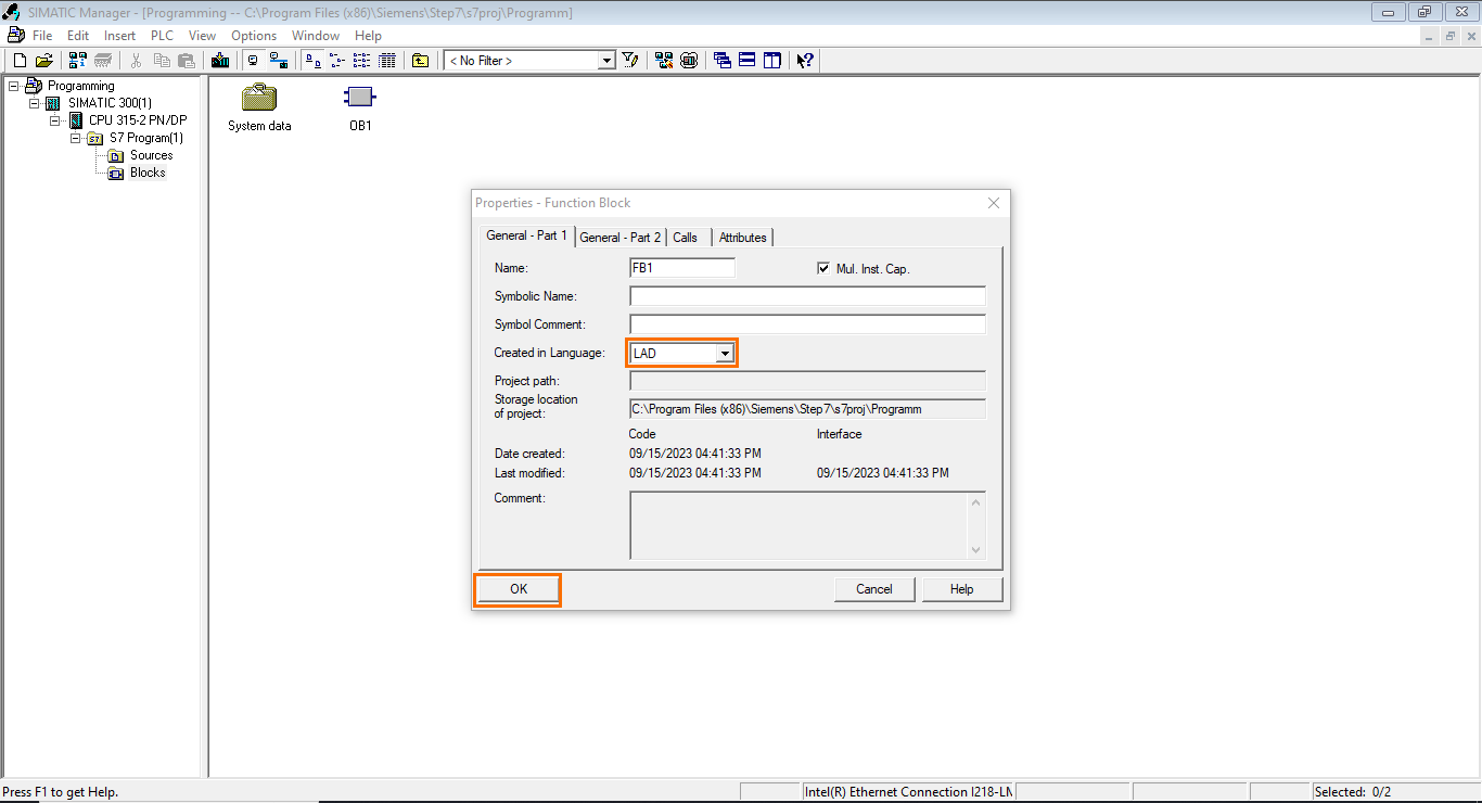
In the properties window of the FB, select “LAD” in the language list and click “OK.”
Once done, the Function Block (FB1) is created. We can now proceed to its programming.
LADDER programming
Building the program
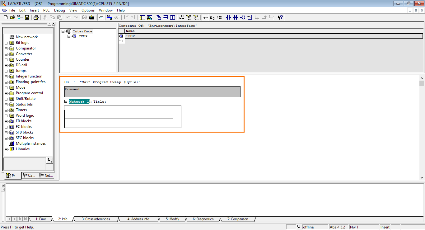
We will now program the motor control application inside FB1. First, Open FB1. A new window will open containing the programming interface.
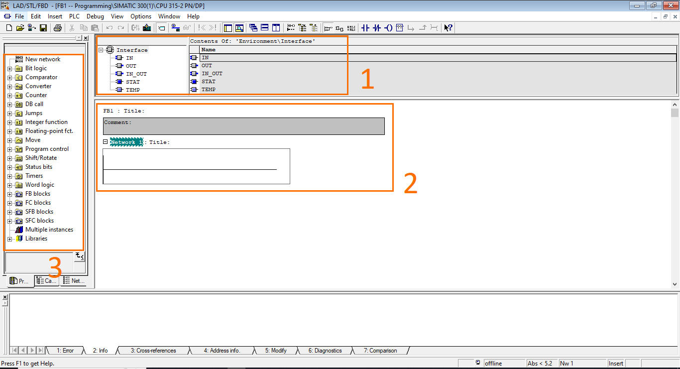
The programming interface is split as follows:
- Block interface: Here, you can define the block’s input, output, and temporary variable. Inputs and outputs are arguments used in the block call.
- Workspace: Here, you can assemble instructions to form your program. You can split the program into different networks for better readability.
- Instructions list: Here, you can find a list of all the instructions, functions, function blocks, and libraries that can be used in your program.
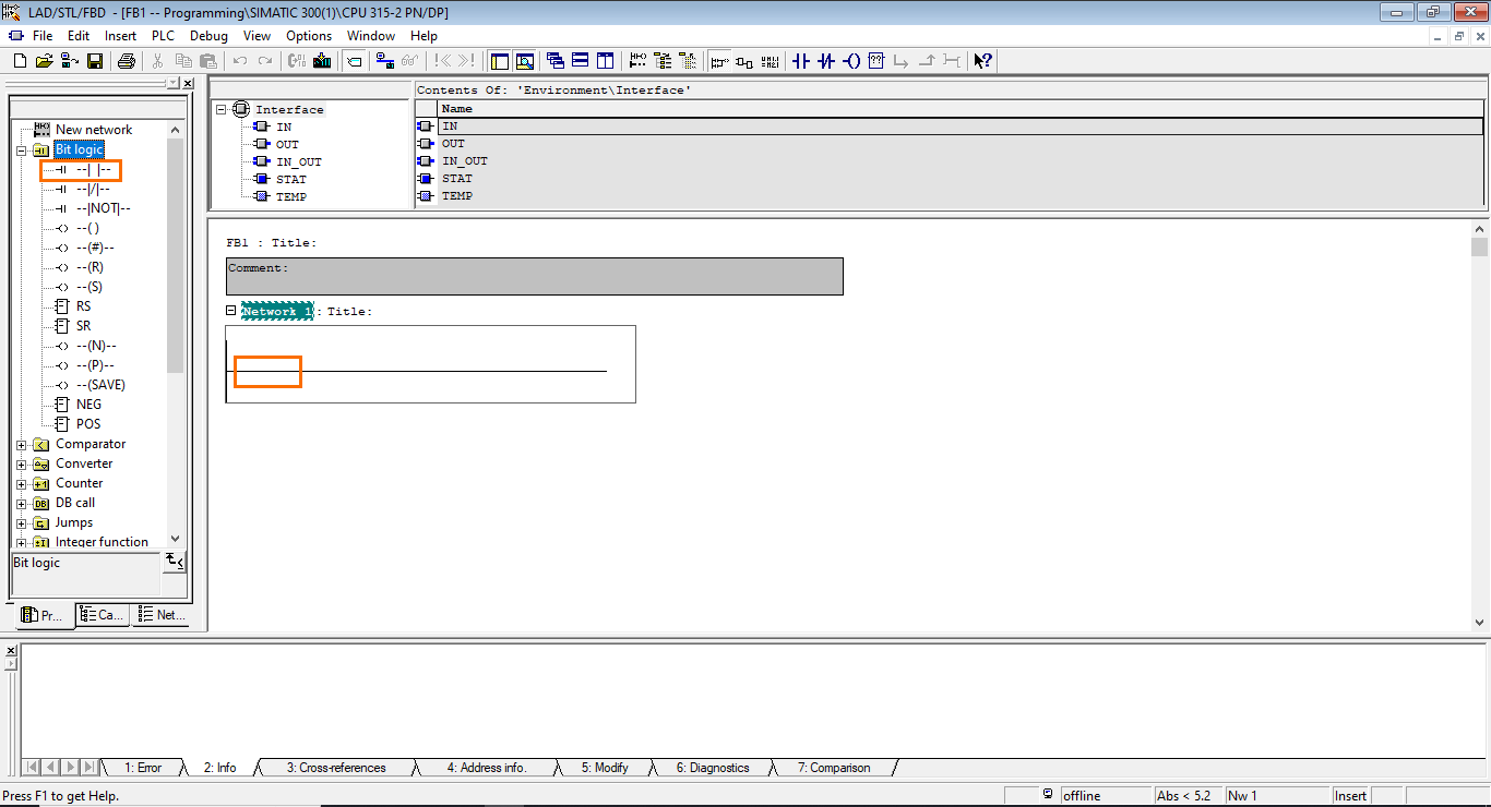
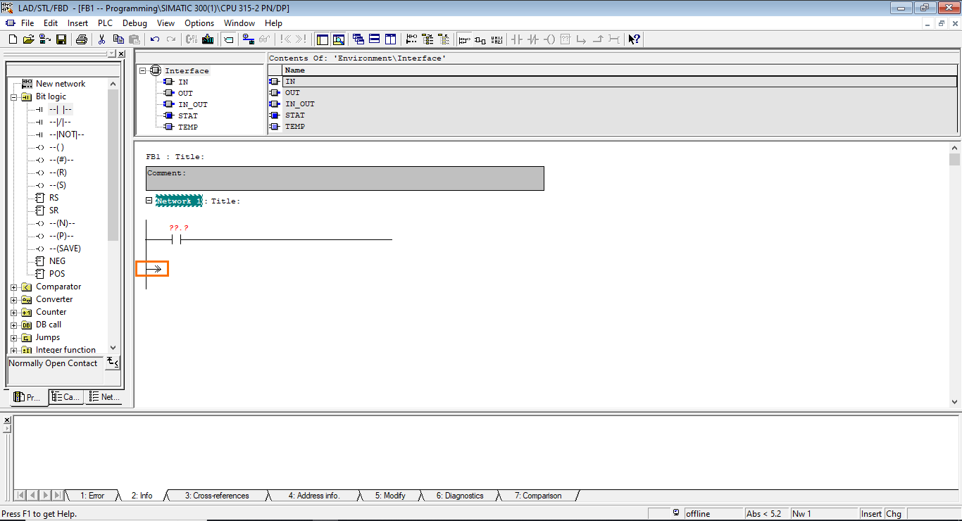
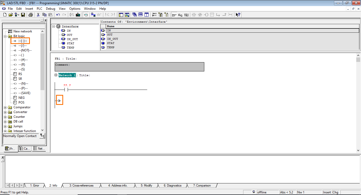
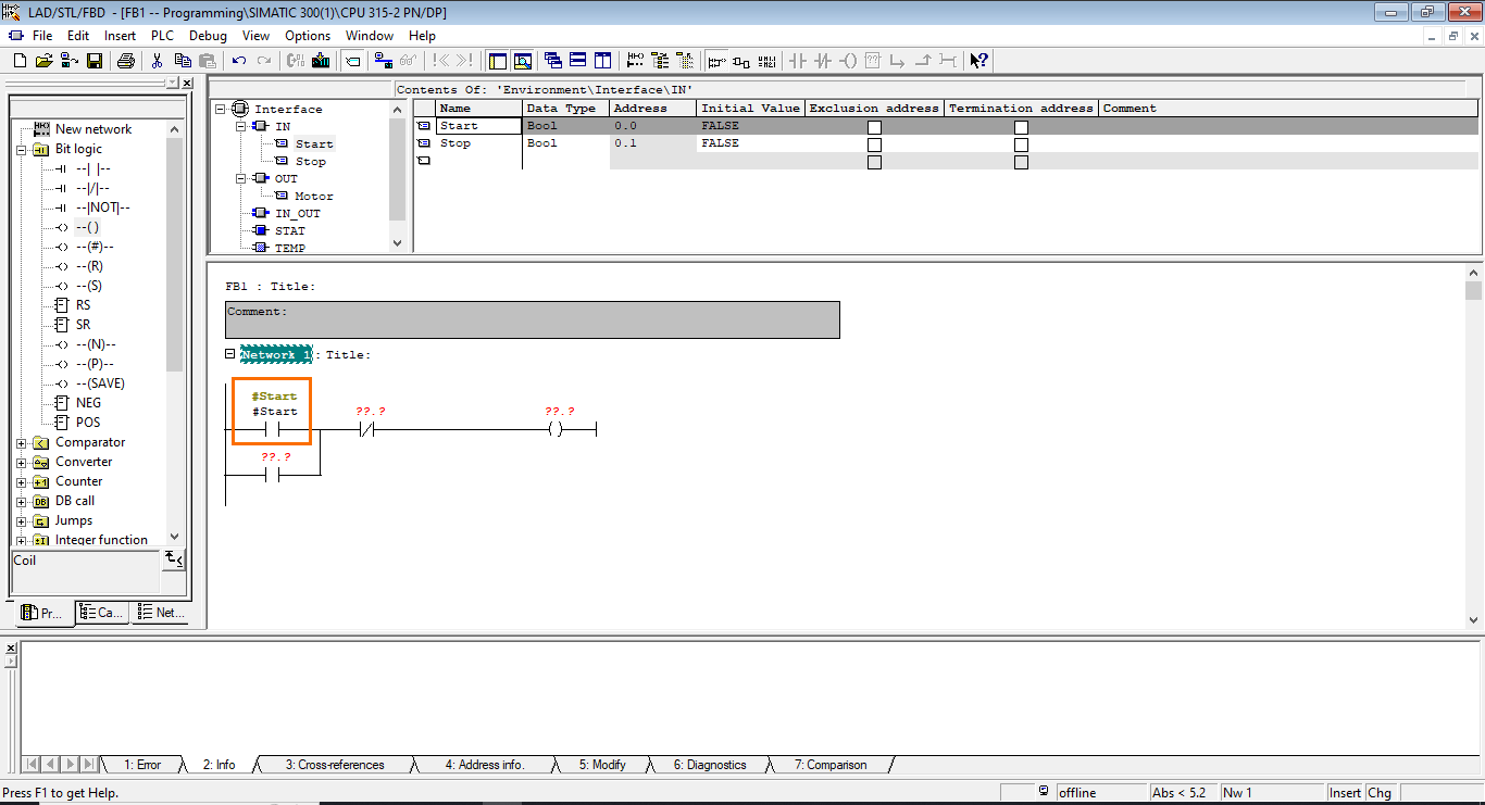
Let’s start building the program. First, open the “Bit logic” folder in the instruction list and drag a NO contact to your first network.
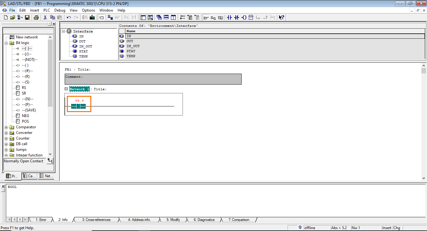
Once done, a NO contact instruction will appear in the network. It is used to interrogate the state of a boolean variable. The red question marks “??.?” indicate that no variable is associated with this instruction.
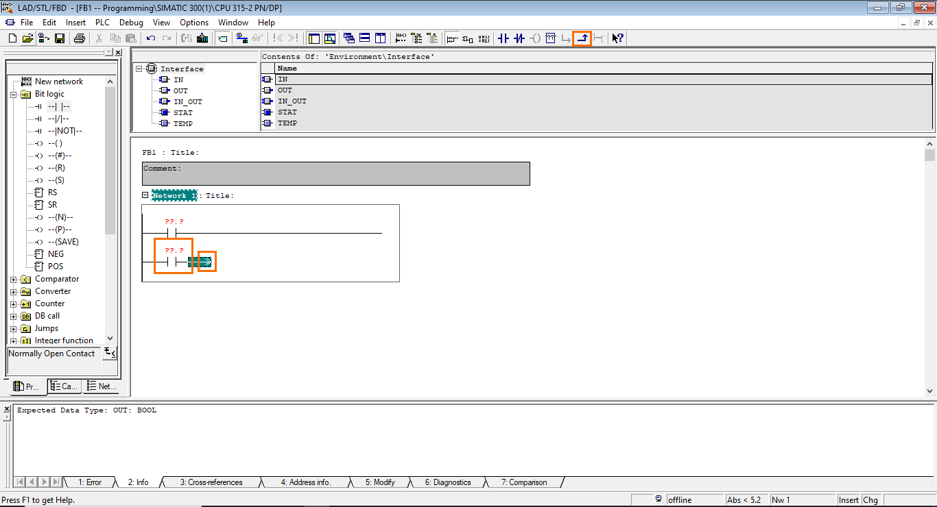
After that, we must create a parallel branch (OR branch). To do this, select the space before the NO contact and click the “Insert branch” button.
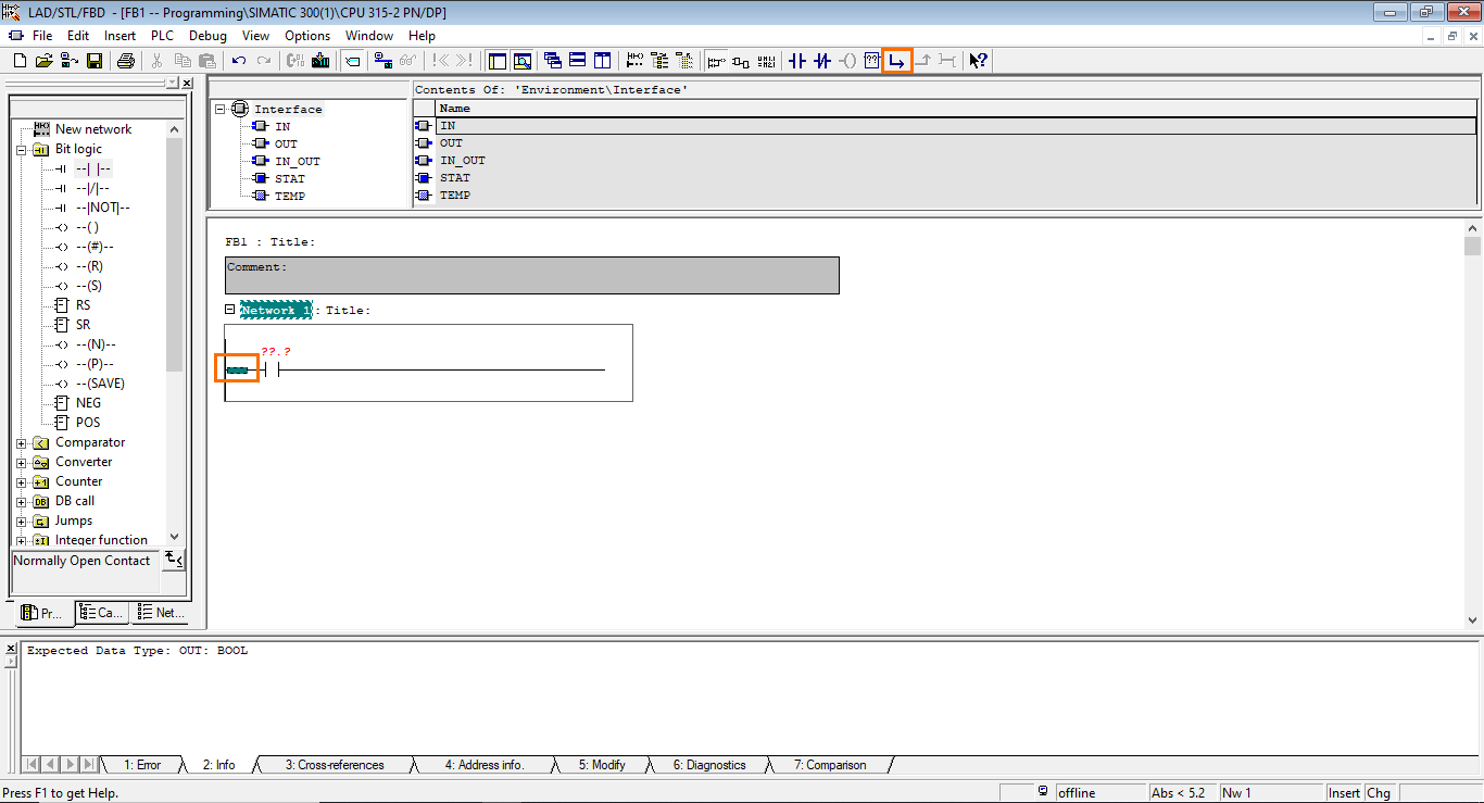
Once done, a new branch will be created below the first one.
Now, add another NO contact in the newly created branch.
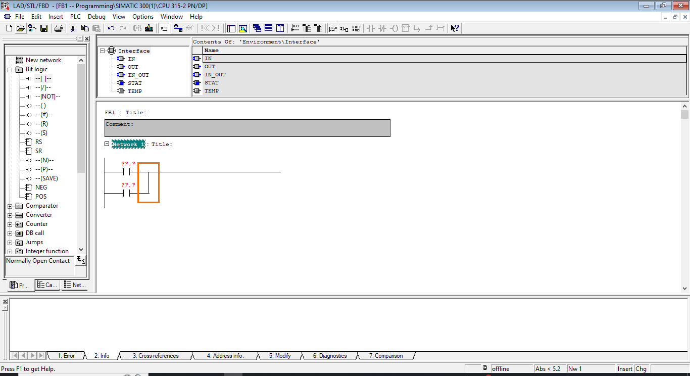
Then, we need to close the branch. Select the branch end and click the “Close branch” button to do this.
Once done, the second branch will be closed to join the first one.
We have formed an OR logic operation between the first two NO contacts; we can move to the next section of the program. We now need to add an NC contact in the main branch. Select the central unit and drag an NC contact to it to do this.
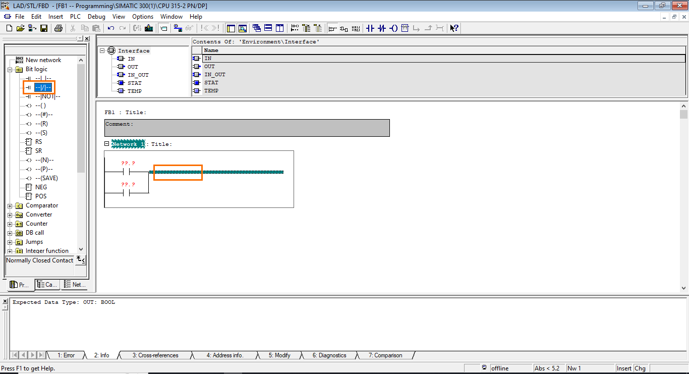
The NC contact is an inverted NO contact. It is used to interrogate a boolean variable but enables itself on the 0 state instead of the 1.
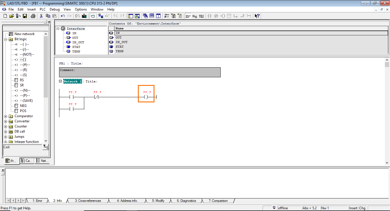
Then, for the last instruction, we need to add an assignment. Drag an assignment instruction to the end of the main branch.
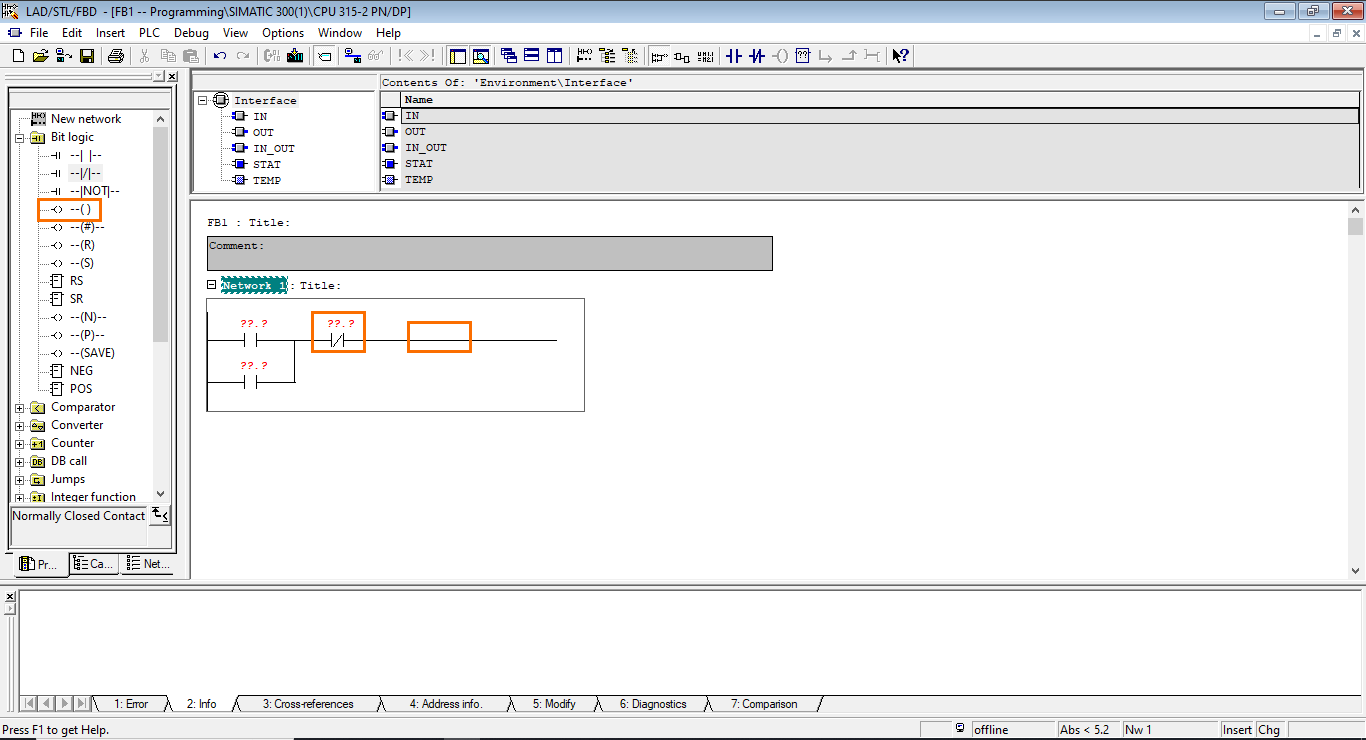
Assignment instructions copy the logic result of all the previous instructions into another variable. It is symbolized by two brackets ().
Block interface
Now that we have built the program, we need to add some variables to use it. For this, we will use the block interface. We will configure inputs and outputs to make the block reusable and later call it using them.
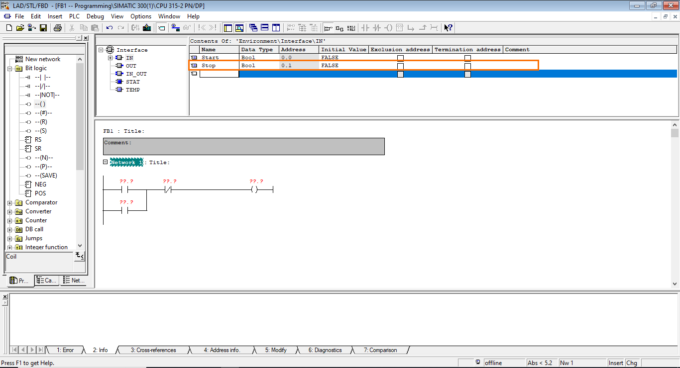
First, open the input section (IN). Here, you can define the input variables of the block.

In the name section, type “Start” and press enter to define the variable that will enable the motor.
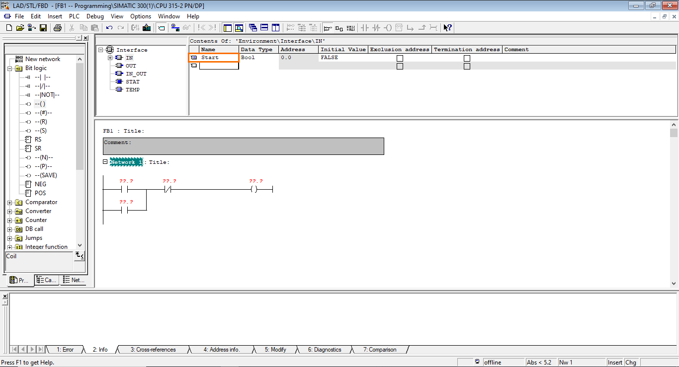
By default, the variable is created as a boolean, and that’s what we need, so keep it like that.
Next, do the same to create a “Stop” input that will be used to turn off the motor.
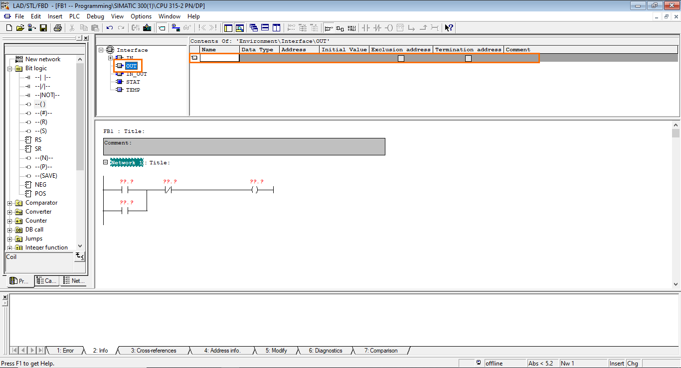
Now, head to the output section, where we will create an output variable to command the motor.
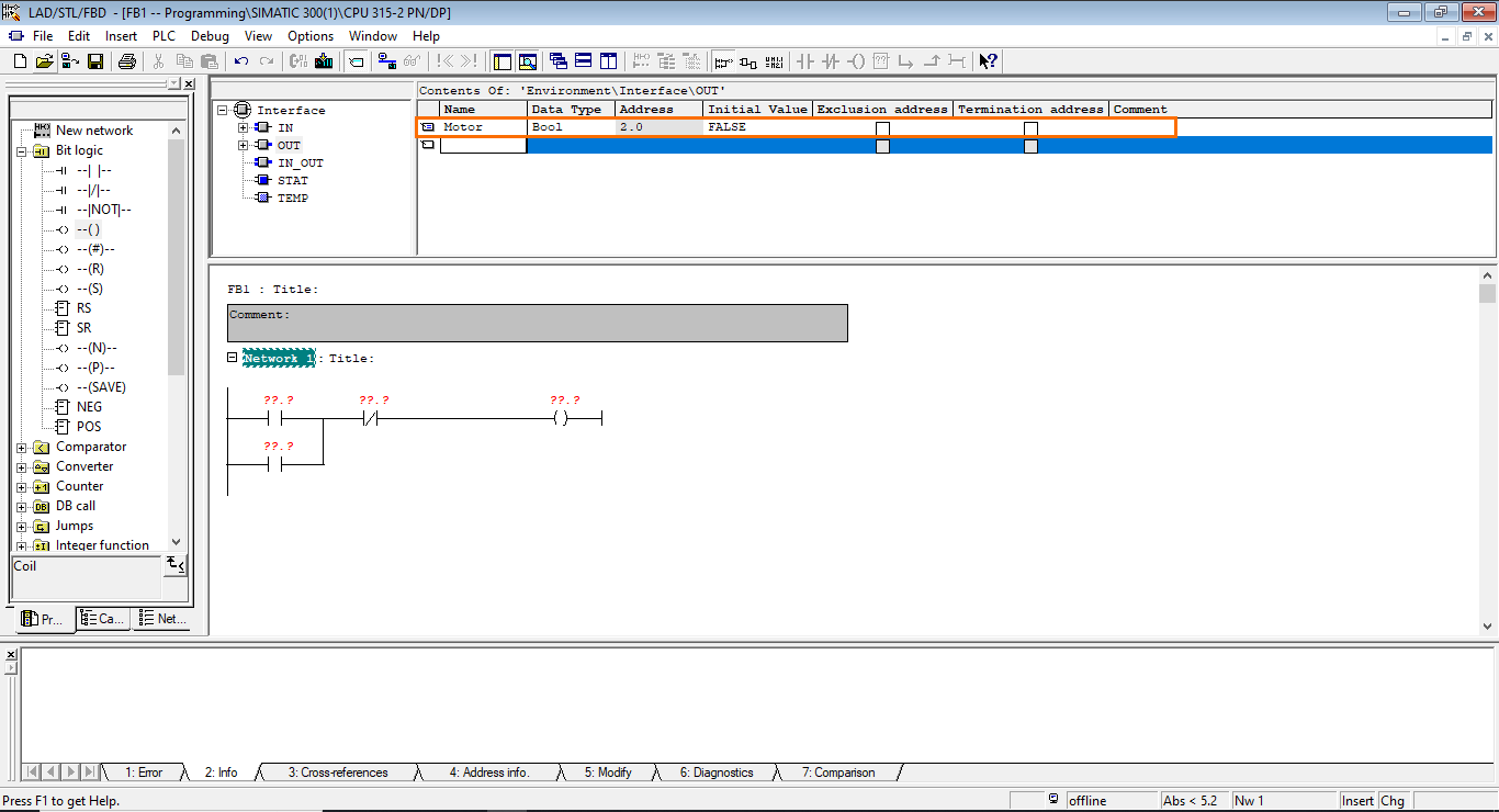
In the name section, type “Motor” and press enter. This will create a boolean output.
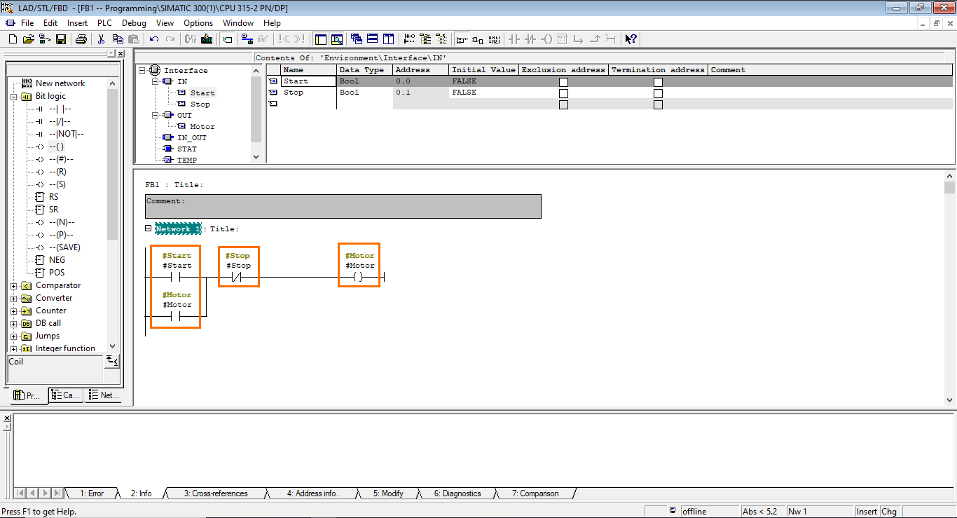
We have defined all the variables we need. Now, we have to add them to the program. To do this, click on the variable section of the first instruction. Here, you can either type the desired variable's name directly or choose it in a list of all the available variables. Select the “Start” variable.
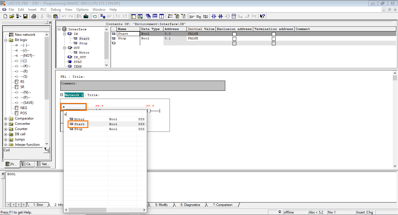
Once done, the variable will appear above its associated instruction.
Repeat this same operation to add variables to all instructions, as shown in the following figure.
Function Block call
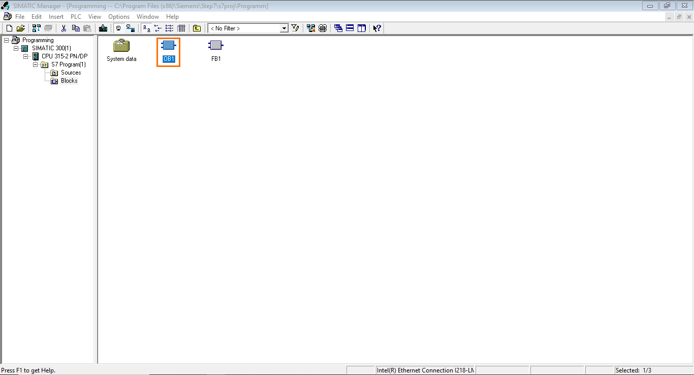
We are done with the programming of FB1. Next, we need to call FB1 in the main cyclic program (OB1). Go back to the main interface of SIMATIC Manager and open OB1.
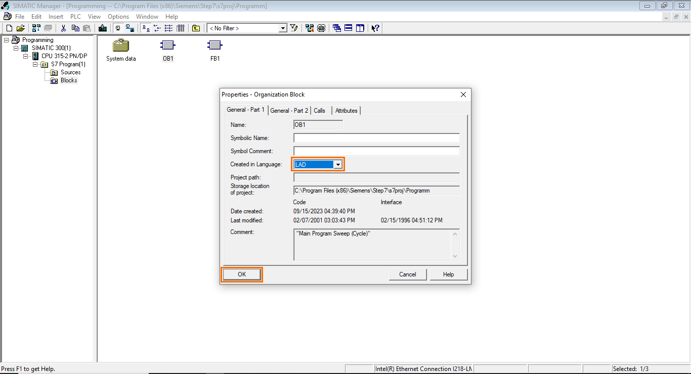
In OB1’s properties, select the LADDER language and click “OK.”
We arrive at a window identical to that of FB1, where we previously had the same interface. We will call FB1 in the first network of OB1.
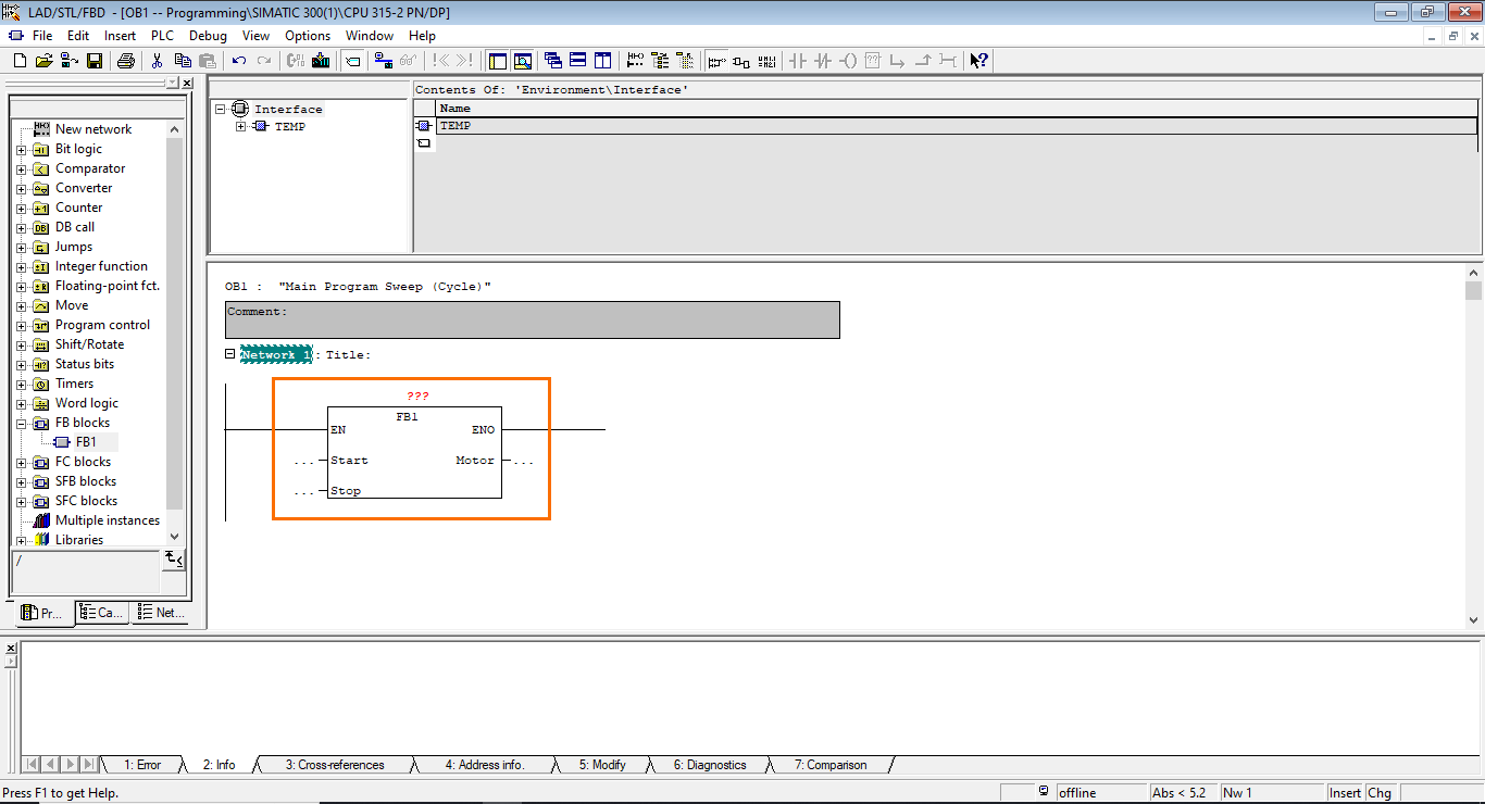
Open the “FB blocks” folder in the instructions list. Here, you will find all the FBs created in your project. Select FB1 and drag it to network 1.
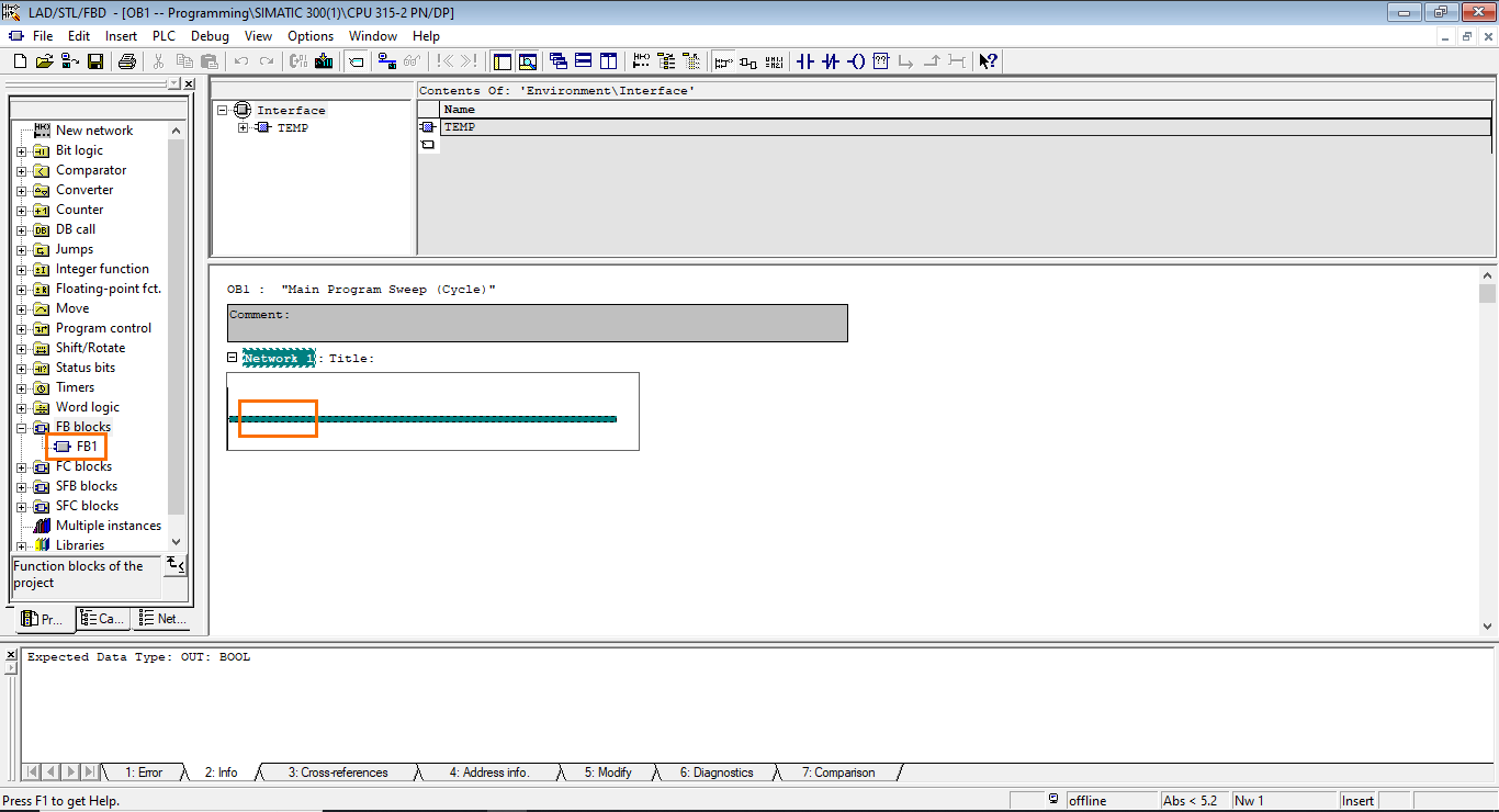
Once done, a Function Block call will appear in the network. The first thing to notice is the arguments of the block,, which are the interface inputs and output we defined earlier. Furthermore, the block is missing its instance DB, indicated by the three red question marks above it. All FBs must be associated with a DB when they're called.
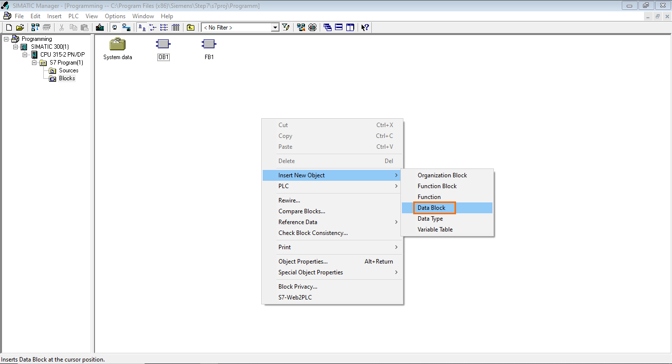
Let’s create the instance DB. To do this, go back to SIMATIC Manager’s main interface and right-click anywhere in the workspace. After that, go to “Insert Nw Object” and select “Data Block.”
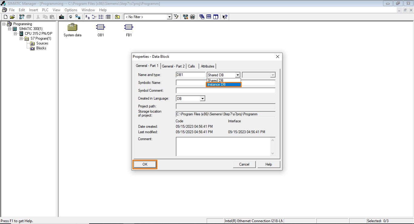
Then, in the DB’s properties, the default DB type is set to “Shared DB” which means that this is a global DB. We need to change the type to make it an instance DB.

Open the types list and select “Instance DB.”
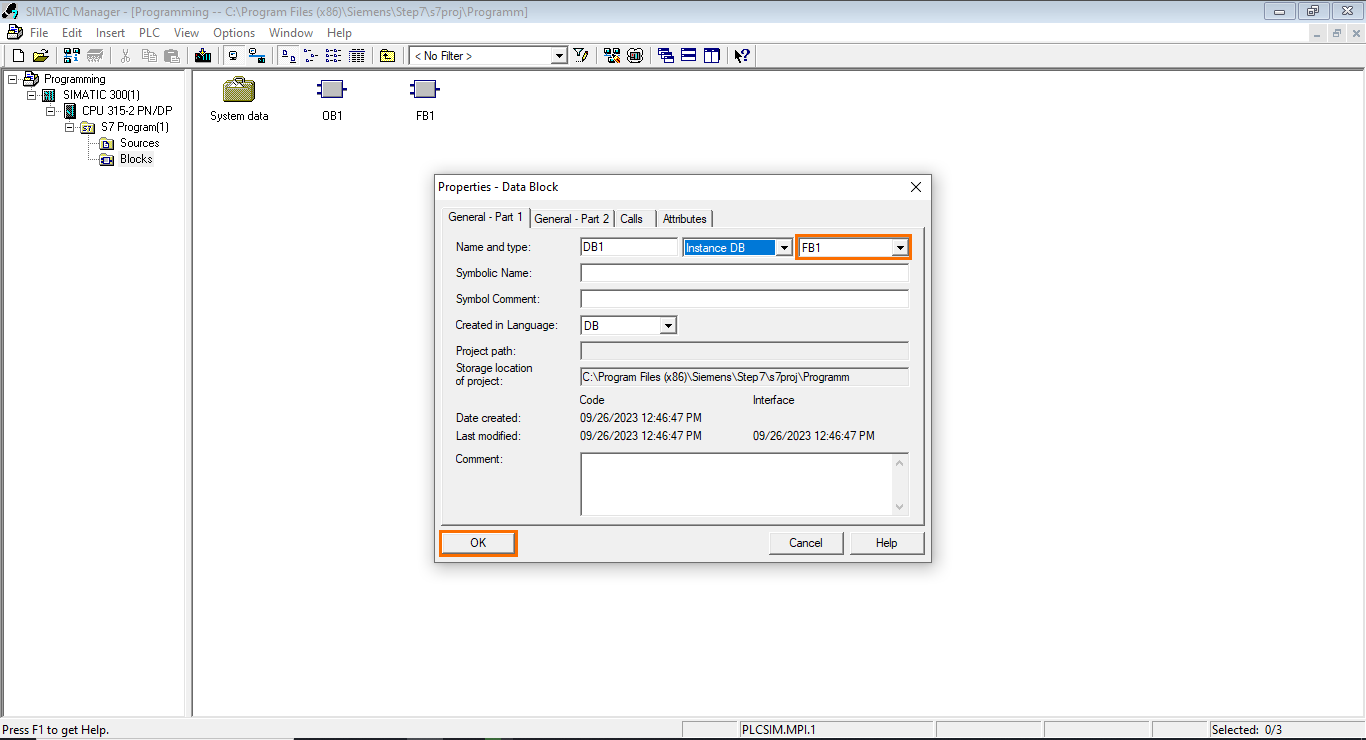
Once done, the next field becomes available where you can indicate its associated FB. Since FB1 is the only FB present in the project, it is selected by default. Finish by clicking on “OK.”
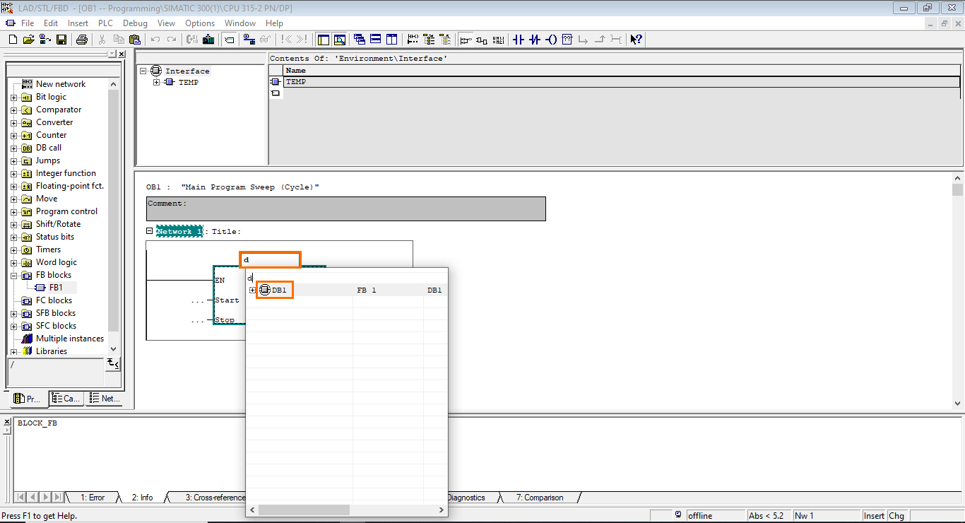
Now, go back to the OB1. We need to add the DB1 to the FB1 call. To do so, you can apply the same logic as we did to add variables to the FB1 instructions. Select “DB1” in the suggestions list.
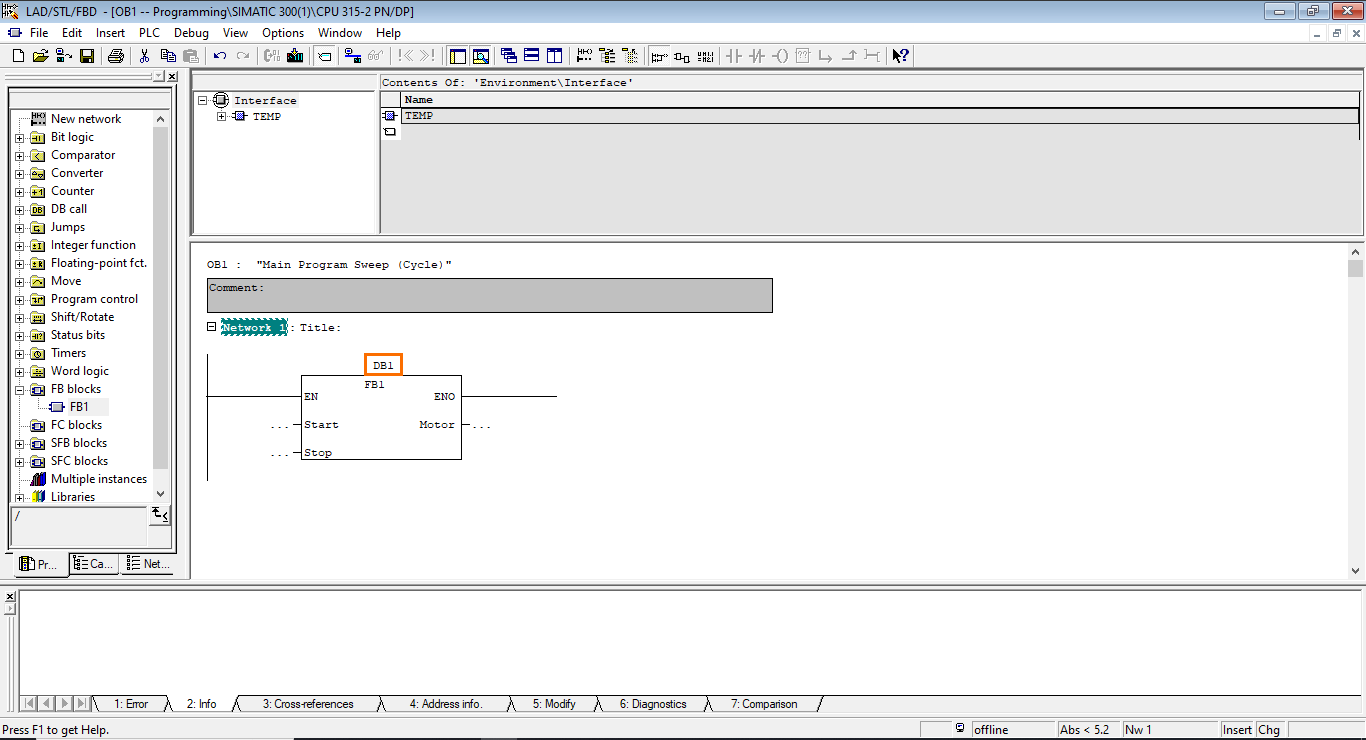
Once done, DB1 is added to FB1’s call.
Symbol Table
The last step of this tutorial is to add physical inputs and outputs to the function call. It is possible to enter the desired input/output address simply, but more is needed for the program's readability. Therefore, we will use a Symbol table, which allows us to associate symbolic names with memory addresses.
To do so, in OB1’s programming interface, open the “Options” menu and click on “Symbol Table.”
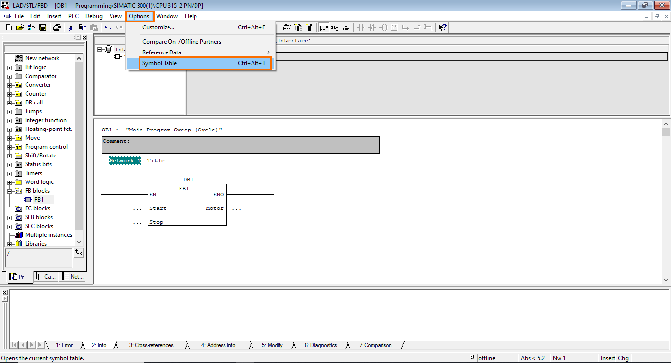
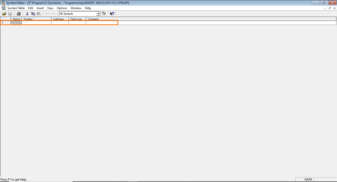
The symbol table will open in a new window. Here, you can define symbolic names for the input, output, and memory addresses used in your program, offering better readability.
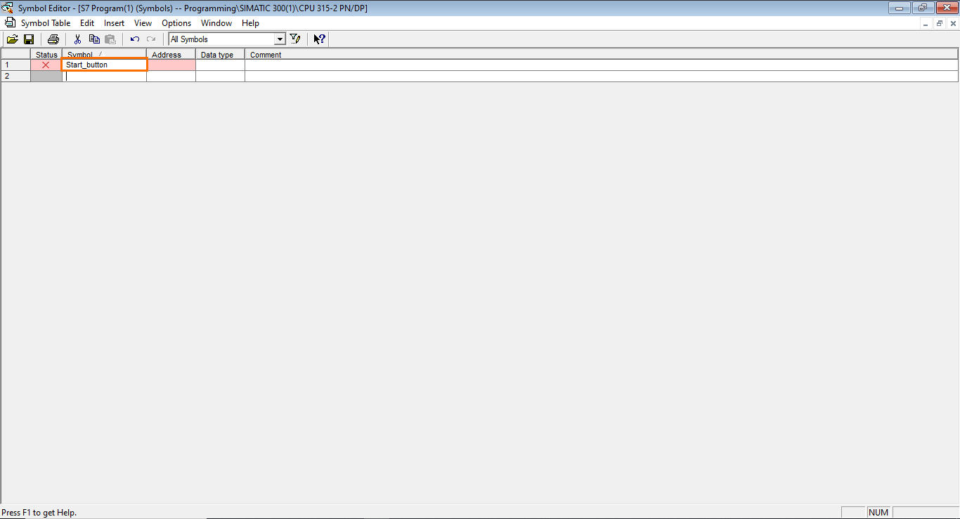
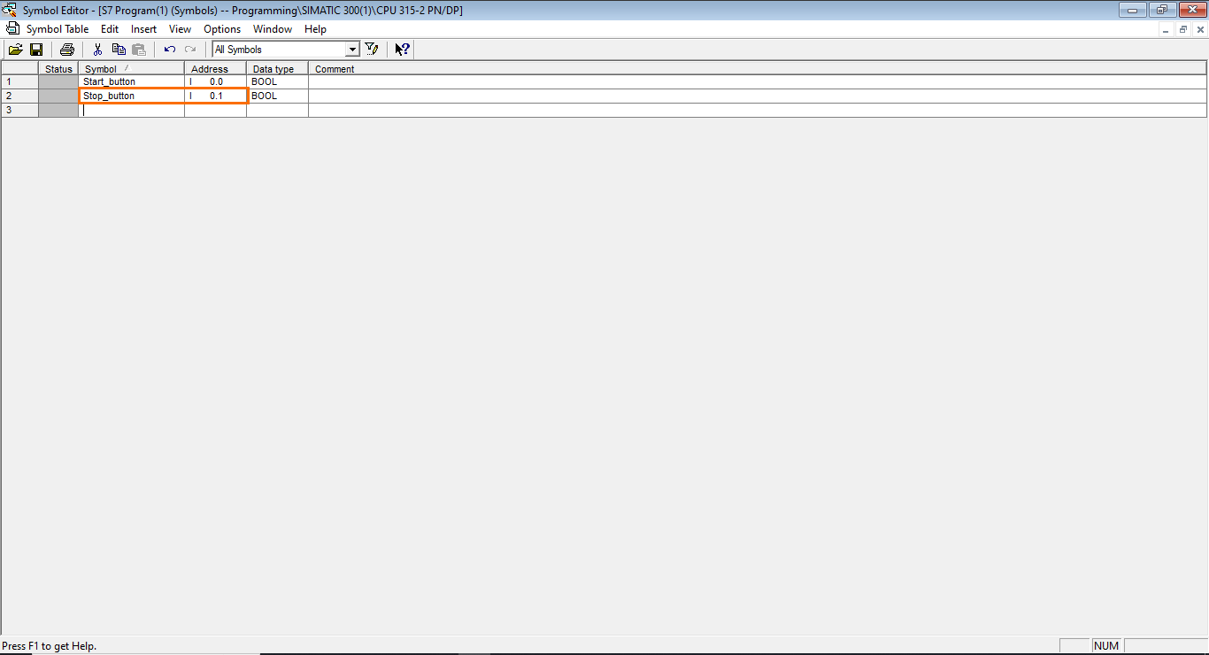
In our motor control application, we need two physical inputs (one for the start button and the other for the stop button). and one physical output (that commands the motor). Let’s start by defining the start button symbol. To do this, simply type “Start_button” in the Symbol section and press enter.
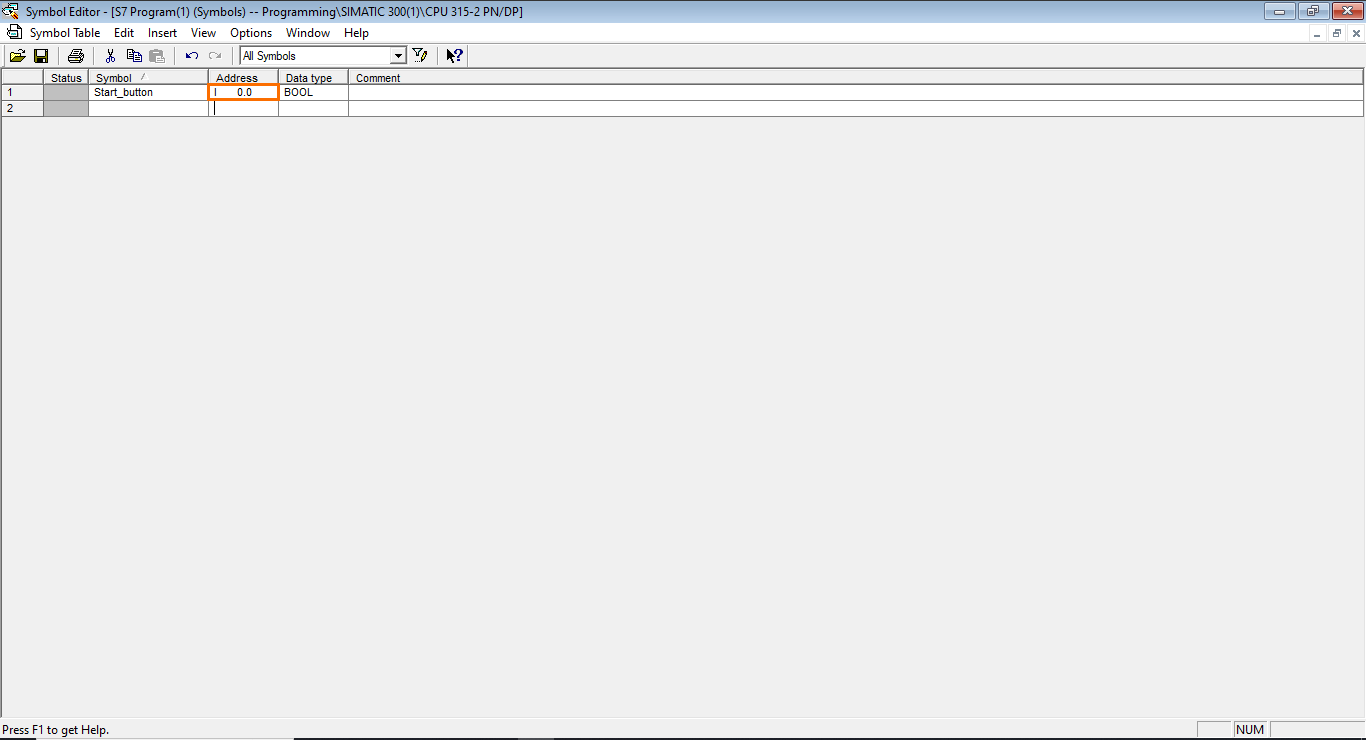
After that, we need to specify the address of the physical input. We will use the first input available in the module so it is “I 0.0”
Repeat this same operation to add a “Stop_button” symbol in the I 0.1 address.
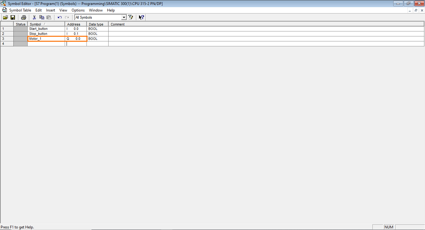
Then, for the motor output, repeat once again the same operation but use the Q 0.0 address to indicate that it's a physical output.
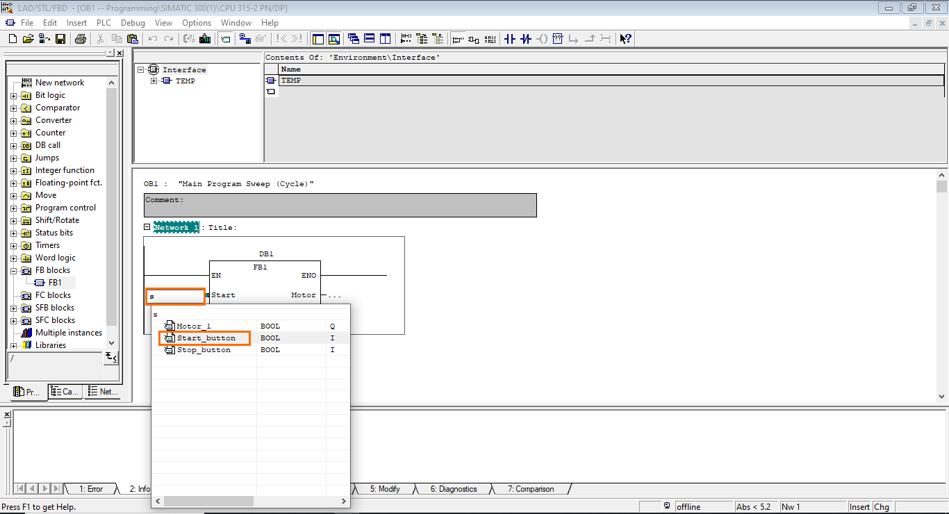
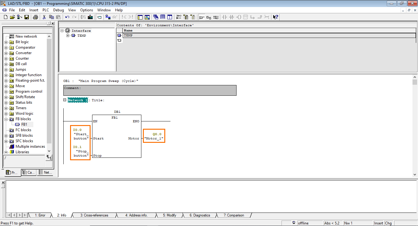
We are done defining the symbols, we can add them to the block call. In the same way as when we added variables to the FB1 program, add the “Start_button” symbol to the “Start” input of the block call.
This will add the symbol with its address to the “Start” input field.
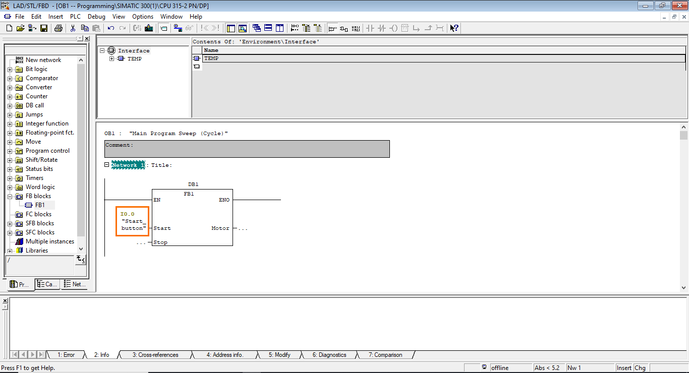
Then repeat this operation to add the corresponding symbols to the I/Os as shown in the following figure.
Conclusion
In this tutorial, you learned how to navigate Siemens' SIMATIC Manager to set up a project and program a motor control application using the LADDER language. We started by creating a project, configuring an S7-300 station, and designing a Function Block (FB1) to execute our motor control logic. After that, we built a program within the FB1, established logical connections, and defined variables for enhanced control. We also explored the integration of this Function Block into the main cyclic program (OB1) and improved program readability using a Symbol table.
As you move forward in your journey of PLC programming, the next crucial step is to test your program's functionality using simulation. Simulation allows you to verify the logic and functionality of your program without affecting real-world processes and equipment. This will be the subject of the SIMATIC Manager PLCSim tutorial.
