

BiSS C Encoder Configuration on a Siemens S7-1500 PLC

Introduction
Encoder feedback on the S7-1500 usually means picking between incremental, SSI, or whatever the drive vendor bundles in, and none of those options handle noisy environments or long cable runs particularly well. BiSS C changes that equation. Every data package is checked for corruption in real time, point-to-point wiring keeps things simple, and you still get full access to Motion Control functions like position filtering, axis synchronization, and event-based capture. If you're building a machine where a dropped or corrupted position value isn't an option, or you're just tired of fighting signal integrity on long runs, this setup is worth understanding properly.
Application Overview
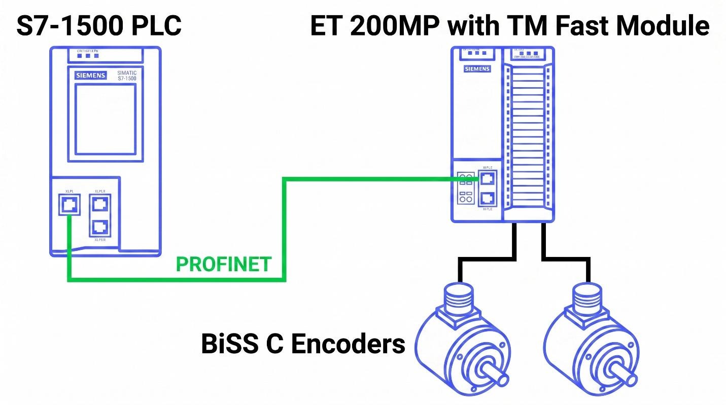
Everything needed to get the TM FAST functioning as a BiSS C encoder interface module is covered in this example. With the included program running, the module reads out position values from the attached BiSS C encoders. This provides the S7-1500 PLC with access to an additional encoder type for position acquisition tasks.
BiSS C Protocol
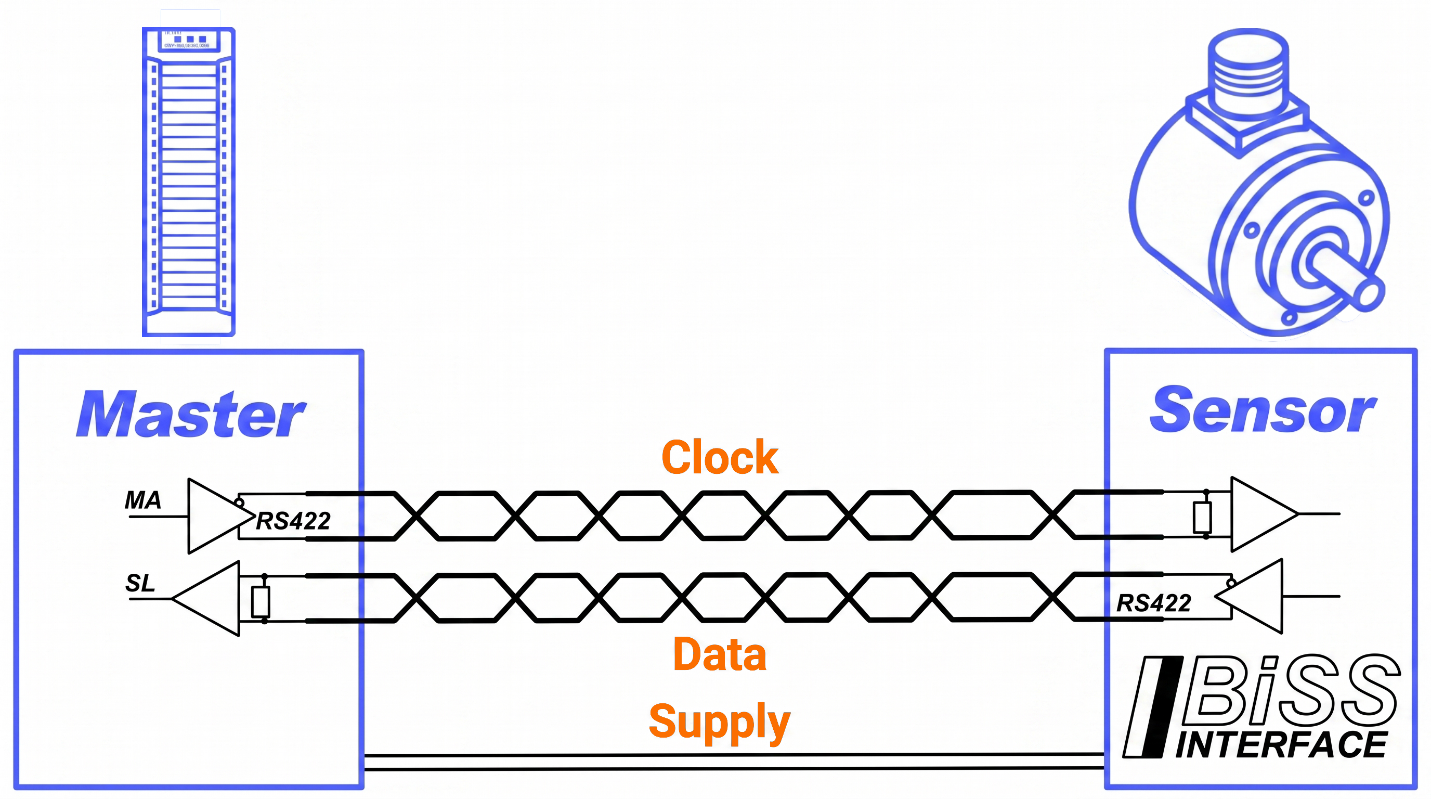
As a protocol, BiSS C transmits process data serially and isochronously. CRC checking is applied to every data package BiSS C sends. Because BiSS C continuously checks transmitted data for corruption, machine safety ends up considerably improved. BiSS C's full capability includes daisy chaining and actuator output, yet what's implemented here is restricted to point-to-point communication and reading encoder data. BiSS C encoders feed input data through the "ExternalEncoder" Technology Object. Using this setup, the encoder data can be processed with the TO_ExternalEncoder's Motion Control functionality. Typical functions include smoothing and extrapolating position data, synchronizing axis motion with an encoder, capturing the current encoder position when a sensor changes state, and changing output states according to the encoder position.
Working Principle
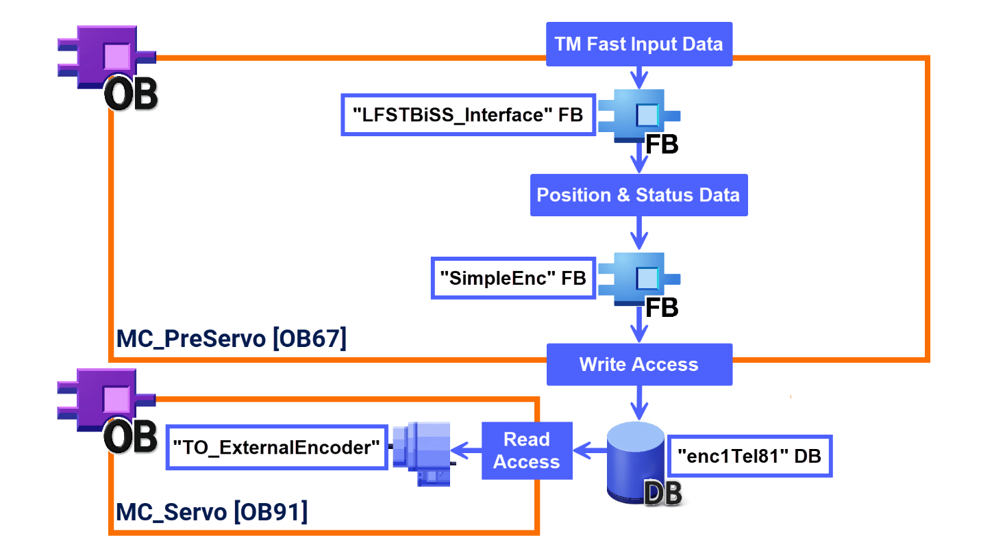
The function blocks responsible for data processing are called from within the "MC_PreServo" organization block environment. TIA Portal automatically triggers "MC_PreServo" immediately ahead of "MC_Servo". Tasks tied to "TO_ExternalEncoder" get executed inside "MC_Servo". There are two roles the "LFSTBiSS_Interface" function block fulfills. At startup, the function block prepares the user program by writing the necessary operating values and BiSS C telegram settings, including CRC-related parameters and data length. The function block, while operating, decodes the TM FAST's incoming data and supplies each encoder's separate position and status information. Formatted according to PROFIdrive telegram 81, the encoder data and states are structured via the "SimpleEnc" FB inside a data block variable. Through a data block connection, "TO_ExternalEncoder" gets hold of whatever data "SimpleEnc" has provided.
Wiring
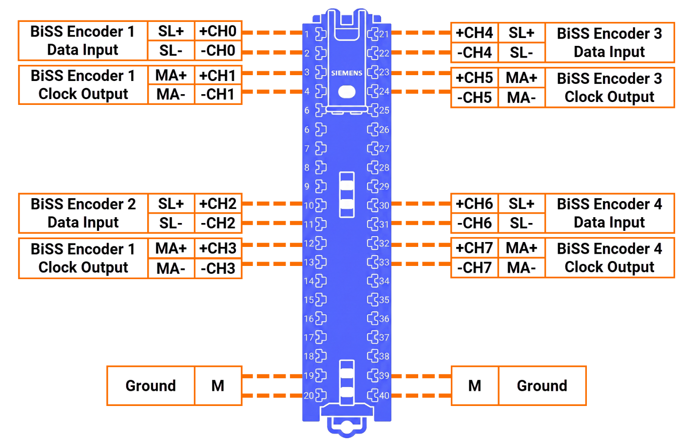
As Figure 4.1 illustrates, the terminals receive the encoders' signal lines through this wiring scheme. An external power supply is mandatory for encoders connected to the TM FAST. According to the BiSS C protocol documentation, RS-422-compliant signal lines are the recommended selection for suitable transmission. Consequently, channels CH0 through CH7, being RS-422-capable, carry the encoder wiring. RS-422 communication holds up better, signal-wise, once terminating resistors are added. Terminating resistors give you the headroom for longer cables than you'd get without them. Channels CH0, CH1, and CH4 on the TM FAST come equipped with terminating resistors.
Adding Technology Object
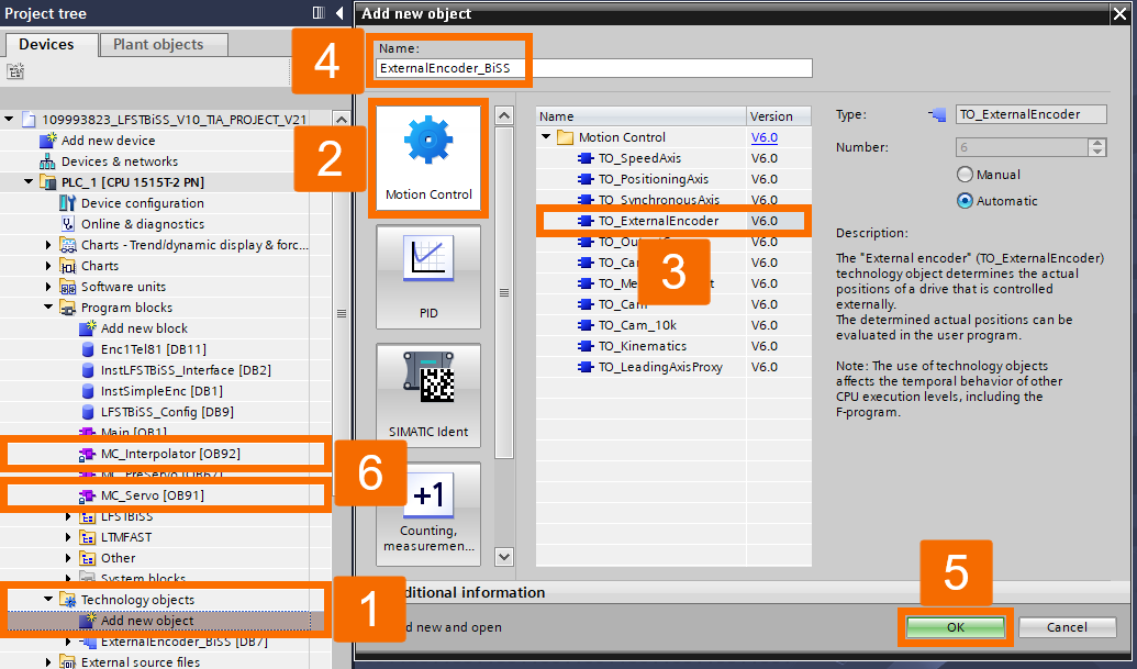
Open the "PLC" folder, drill down into "Technology Objects", double-click on "Add New Object", and choose the "TO_ExternalEncoder" motion control object from the list. Both the "MC_Servo" and "MC_Interpolator" organization blocks get added automatically to your program blocks by TIA Portal. You can't edit these OBs directly, as they serve as the Motion Control runtime environment.
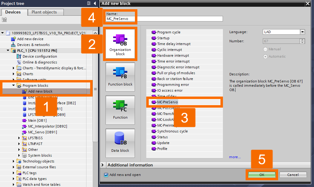
After expanding "Program Blocks" inside the "PLC" folder, double-click "Add New Block" and select "MC_PreServo" to add it as an organization block.
Hardware & Network Configuration
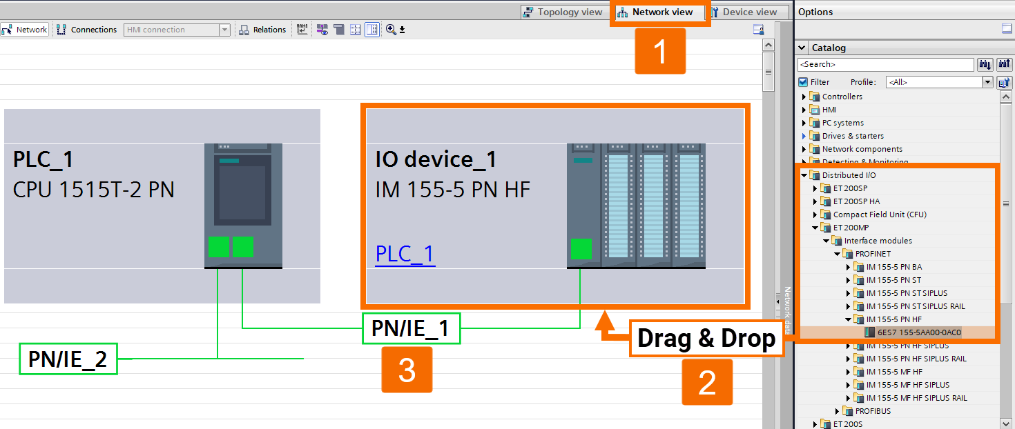
Place an ET 200MP interface module in the hardware configuration. In the "Network View", wire the devices together. The ET 200MP interface module should be connected in "Network View" to the PLC port that supports PROFINET IRT, typically X1. Click-drag on the interface first, then click the PLC interface, and the connection forms.
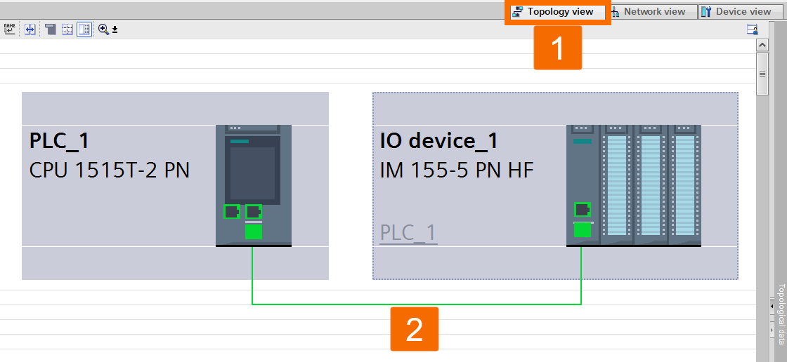
Use "Topology View" to link the devices together.
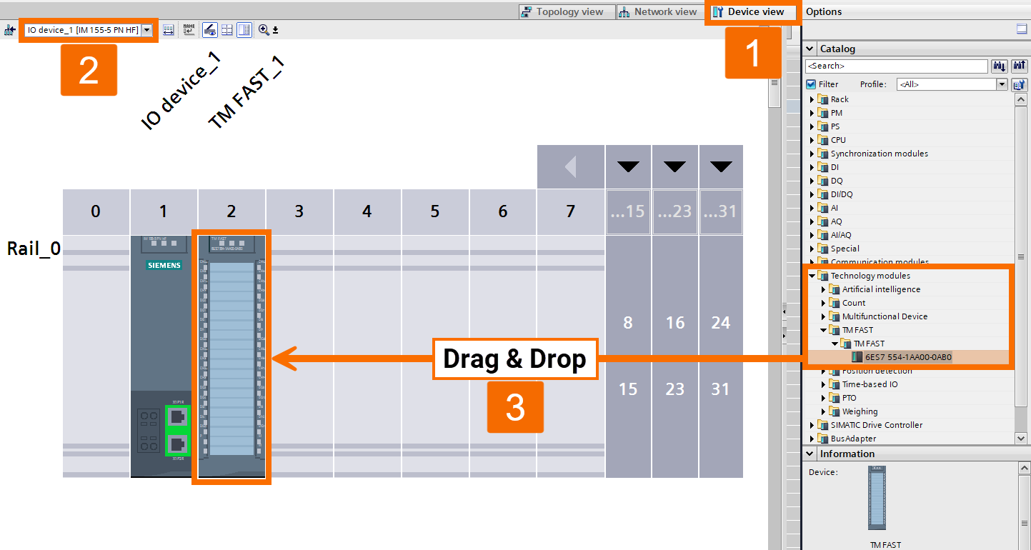
Next, drop in a TM FAST. Attach a TM FAST to the ET200 MP module from within the "Device View". Features found only in TM FAST firmware V2.0 are required by the code provided here. In cases where V2.0 doesn't show up as selectable, install the HSP 368 hardware catalog support package from this link.
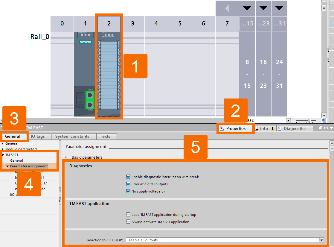
Now configure both the startup behavior and diagnostics settings. Figure 6.4 shows the recommended settings to use for the TM FAST. You can adjust these settings once the module is selected within the ET200 MP's "Device View".
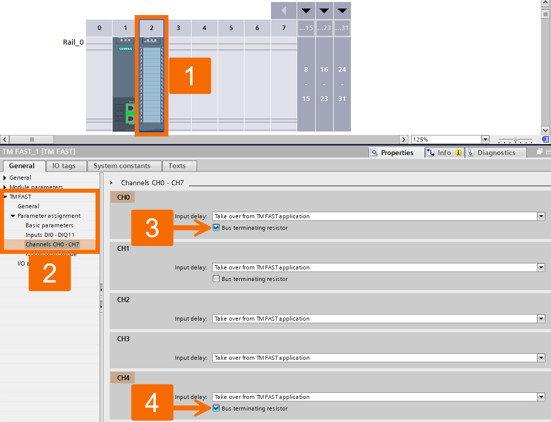
Set up the RS422/485 channels next. Choose "Take over from TM FAST application" as the value for input delay. Turn on the bus terminating resistor for the CH0 and CH4 channels.
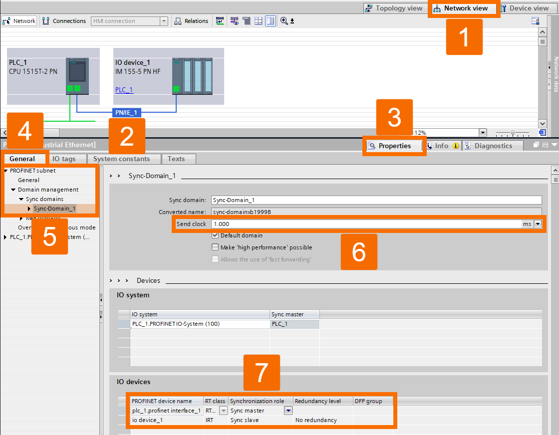
In the next step, set up isochronous mode along with "PROFINET Send Slock" and the "Sync-Domain". Click "PN/IE_1" to get to the "Sync-Domain" configuration screen. From "PROFINET Subnet", open "Domain Management", expand the "Sync Domains" item beneath it, and select "Sync-Domain_1" to proceed. The default 1 millisecond value for "Send Clock" works for most applications, so leave it alone. Assign "IRT" as RT class to both devices, set the PLC's role to "Sync Master", and set the ET 200MP's role to "Sync Slave".
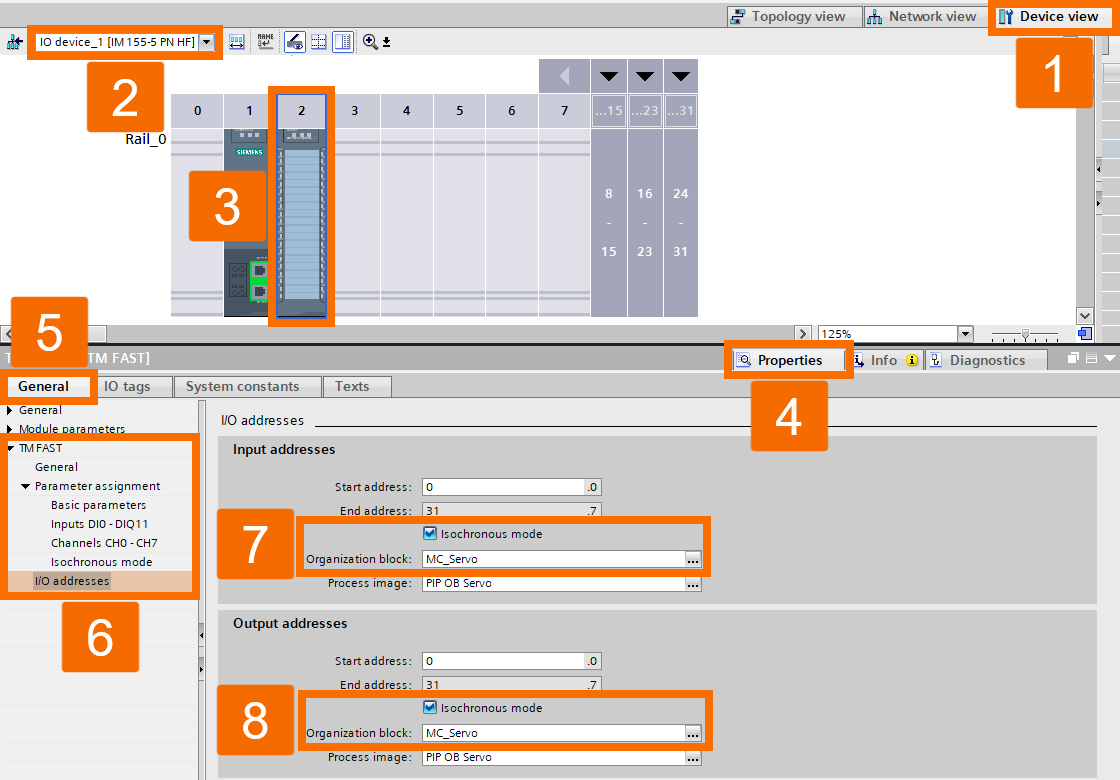
Next, the isochronous mode and a specific organization block should get activated and assigned, respectively. Select the TM FAST from "Device View", then navigate into the "I/O addresses" section. Switch isochronous mode on and assign "MC_Servo" as your organization block.
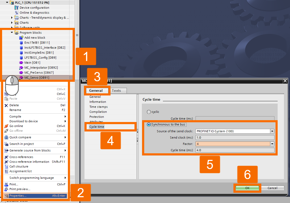
The application cycle needs configuring next. Application cycle configuration lives within the properties of the "MC_Servo" OB. From the right-click menu on "MC_Servo", select "Properties". With the "Properties" window now open, click "Cycle Time" and use the "Factor" setting to define the application cycle time in milliseconds.
BiSS C Encoder Library Setup
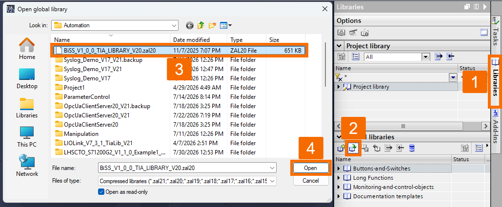
Extract the BiSS C encoder library you grabbed from this link.
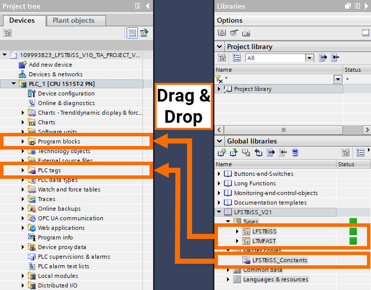
Drop the "LFSTBiSS" and "LTMFAST" library folders into the "Program Blocks" within the "PLC" folder. The PLC data types are populated automatically with the new user data types. Drop the "LFSTBiSS_Constants" tag table into the PLC's existing tag tables.
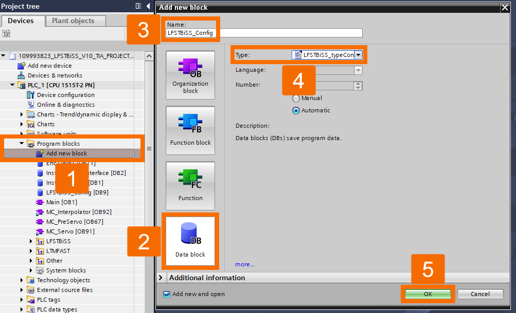
Bring in a new "LFSTBiSS_typeConfig" type data block now. This data block later parametrizes the TM FAST code to suit whichever encoders are connected.
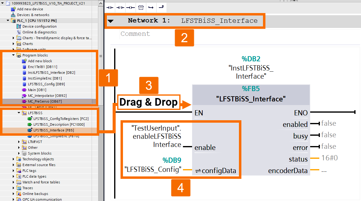
Call "LFSTBiSS_Interface" FB from inside the "MC_PreServo" organization block by adding it in "Network 1". Flipping "Enable" to "True" causes both a TM FAST program restart and a transmission of configuration data.
Passing Encoder Data to Technology Object
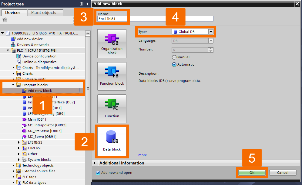
The Technology Object receives encoder data through a data block, enabling its use with "TO_ExternalEncoder". The "SimpleEnc" function block populates the data block with the encoder's position and status data. Create a new "Global DB" type data block.
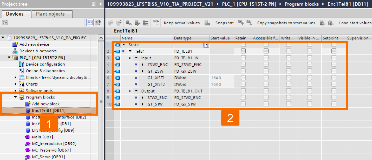
Add a "PD_TEL81" typed field named "Tel81" once you've opened the block.
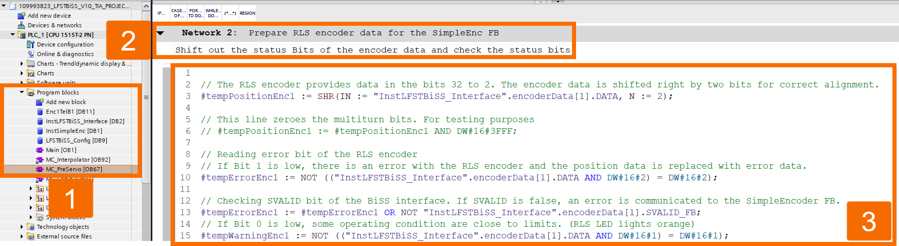
Add an SCL network inside "MC_PreServo" that gets the encoder data ready for the "SimpleEnc" FB.
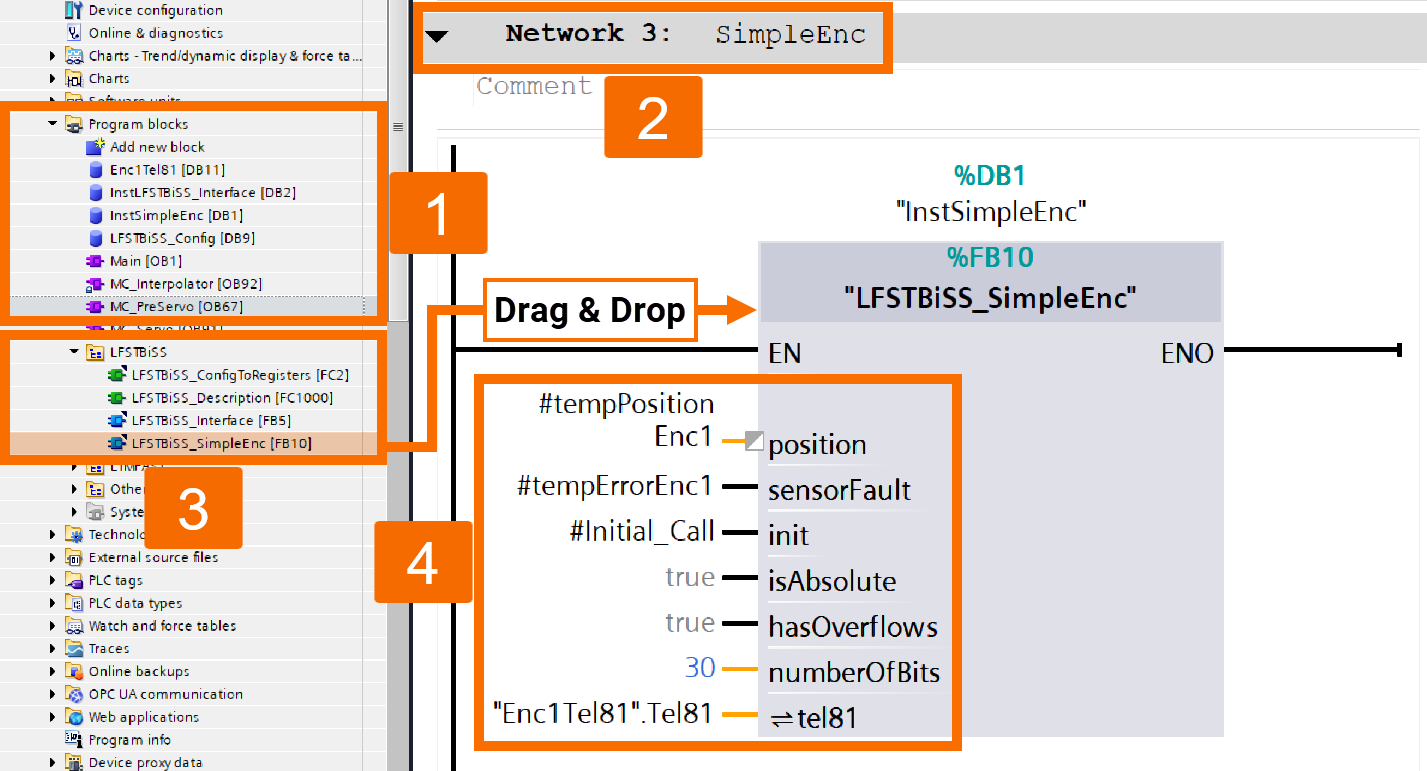
Insert a network to hold the "SimpleEnc" function block. Place this network directly after the network used to prepare the encoder data.
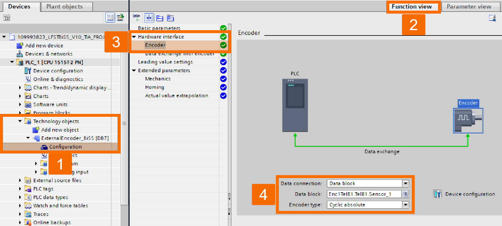
The "Encoder" section of "TO_ExternalEncoder" needs adjusting at this point.
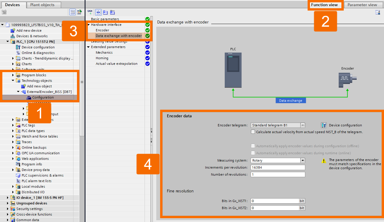
Move on to adjusting "Encoder Data Exchange" settings for the "ExternalEncoder" Technology Object.
Commissioning
Inside the "LFSTBiSS_typeConfig" data block is the parametrization that governs the TM FAST code's operation. Start values in the data block are where configuration data goes.
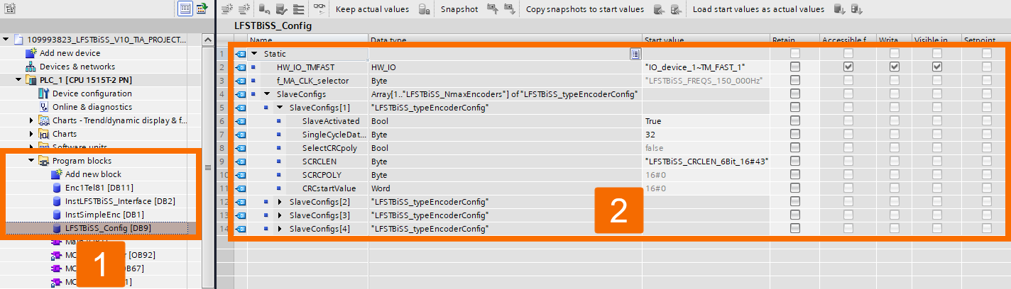
Compile the program, then download it to the PLC.
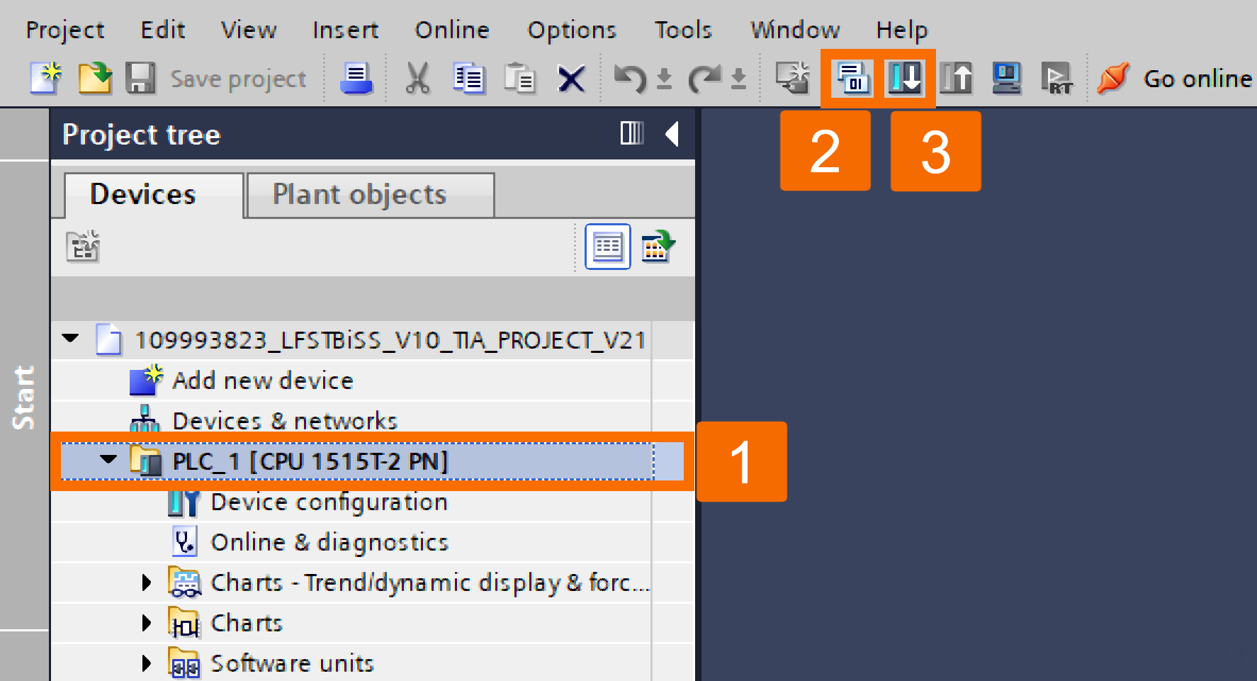
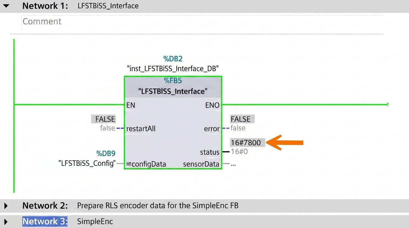
Establish an online connection with the PLC. In the hardware configuration, you now need to set the input processing time. To get there, begin by parametrizing each encoder that will be used. Every encoder needs to be communicated with correctly at this stage. When at least one activated encoder times out despite the rest functioning normally, the "LFSTBiSS_Interface" function block's "status" output shows "16#7800". That behavior is normal since isochronous operation hasn't been configured yet.
Go into the function block's instance data block, "LFSTBiSS_Interface_DB". Record what the "stat_inputProcessingTime_ys" variable shows as its monitor value.

Disconnect from online mode, then head into the hardware configuration. Open the TM FAST interface module's "Device View" screen. Enter the previously observed online value into "Processing time of input data in user logic" as its setting.
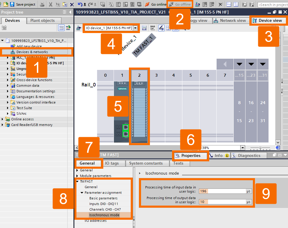
Send the hardware configuration down to the PLC. Double-check that "Status" = "16#7100" (reading position status) is what the "LFSTBiSS_Interface" function block's output shows now.
Conclusion
In conclusion, you have learned how to bring BiSS C encoders into an S7-1500 system using the TM FAST as the interface module. You now know how the "LFSTBiSS_Interface" and "SimpleEnc" function blocks work together to parametrize the TM FAST, unpack incoming encoder data, and hand it off to the "ExternalEncoder" Technology Object through a PROFIdrive telegram 81 structure. You've also walked through wiring encoders to the RS-422-capable channels, configuring isochronous mode and the Sync-Domain in TIA Portal, and commissioning the system by matching the input processing time and confirming the "16#7100" status. That's a complete, working BiSS C setup.


