

CANopen Manager and Slave Configuration on ET 200SP

Introduction
If you've ever stared at a CAN bus network wondering how to get a Siemens ET 200SP talking to it without writing custom drivers from scratch, this is exactly the kind of headache worth solving properly. CANopen isn't going anywhere in industrial automation, and plants running mixed hardware still lean heavily on it for real-time, deterministic communication. Skipping a solid Manager-Slave setup means chasing configuration errors on the shop floor later, usually at the worst possible time. Learning this now, with a clear PROFINET-to-CAN data path in front of you, saves you from that debugging nightmare down the road. It's time well spent.
Application Overview
The CAN communication module opens up a direct connection between the SIMATIC ET 200SP and CAN or CANopen networks. Within the CANopen network, the module can be configured to operate as either a Manager or a Slave, and it supports three operating modes: CANopen Manager, CANopen Slave, and CAN transparent. The ET 200SP distributed IO system requires a pair of CM CAN communication modules, with one assigned the CANopen Manager role and the other assigned the CANopen Slave role. An S7-1500 controller is responsible for loading configuration data across the pair of CAN modules. There has to be ongoing data exchange between the CAN modules and the IO controller, the S7-1500 CPU. Thanks to PROFINET and the 'ET200SPCM_CANConfig' function block, payload and configuration data flow freely between the S7-1500 CPU and the ET 200SP. Once converted into the CAN protocol by the CM module, the data travels over the CAN bus until it reaches the individual nodes. Feedback flows back to the S7-1500 CPU through the same mechanism in reverse. The CAN module decodes the CAN protocol data and, using PROFINET, delivers it to the IO controller.
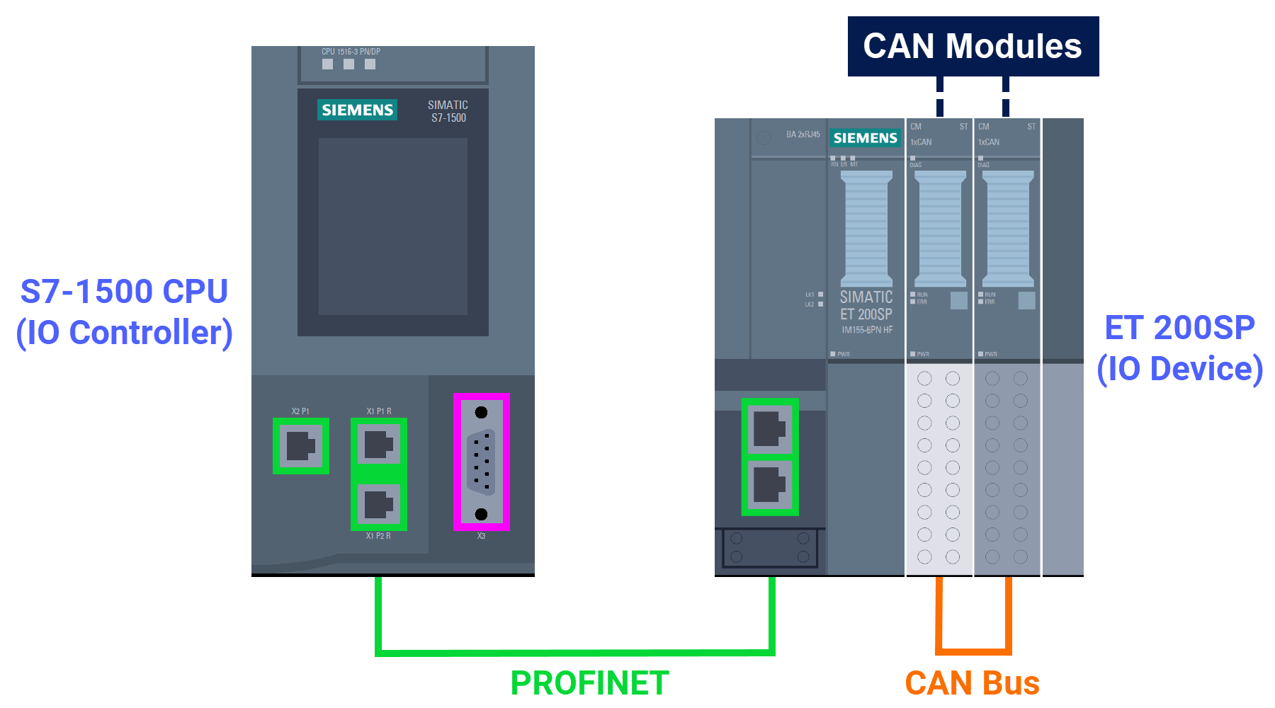
CAN Modules Configuration Sequence
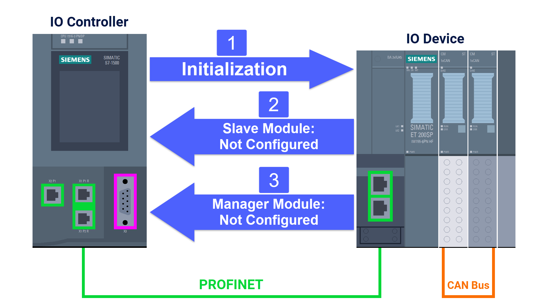
Time to look at the chronological order behind configuring these CAN modules. Everything starts with the S7-1500 controller starting up. The S7-1500 controller receives a 'Not Configured' status message from the 'CM CAN Slave' module. The controller also gets a 'Not Configured' status message, this time from the 'CM CAN Manager' module.
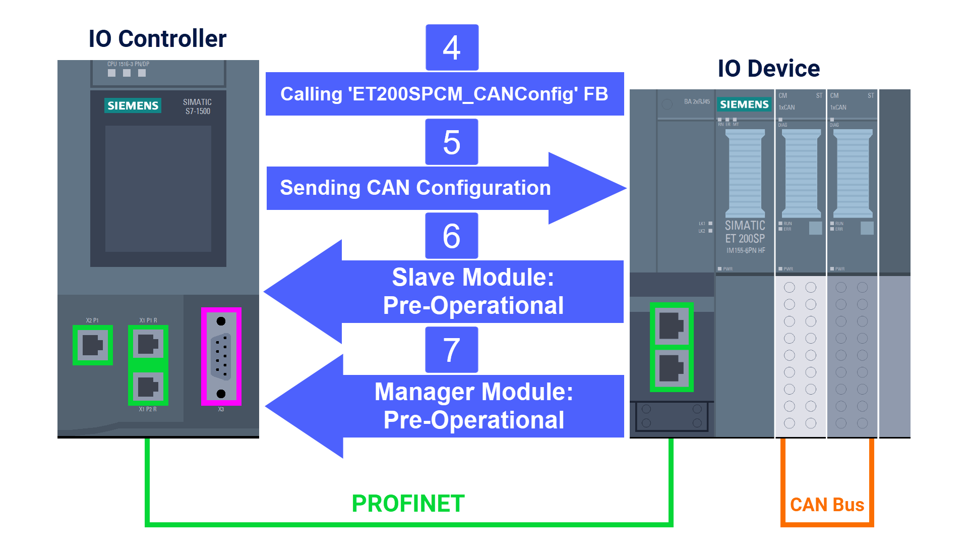
This is where the 'ET200SPCM_CANConfig' function block from the CAN modules library (which you can download here) gets called to swap payload and configuration data. Both 'CM CAN Manager and Slave' receive their configuration data directly from the IO controller. 'CM CAN Manager and Slave' moves into 'PreOperational' and reports that status change to the S7 controller.
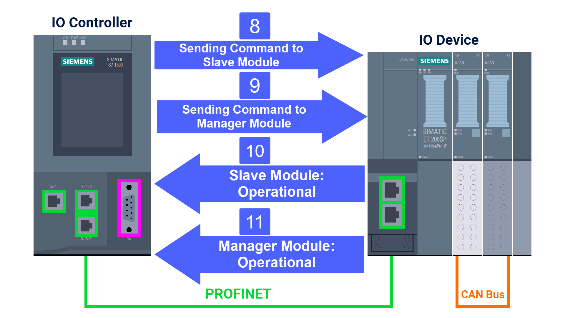
Next, the S7 controller writes 'Set Operational' into the 'CM CAN Slave' module control byte. This step involves the IO controller writing 'Configure nodes (Slaves) and Set Operational' to the 'CM CAN Manager' module control byte. Having completed the transition, the CAN Slave and Manager modules transmit Operational as their status to the S7-1500 controller.
CAN Modules Data Exchange
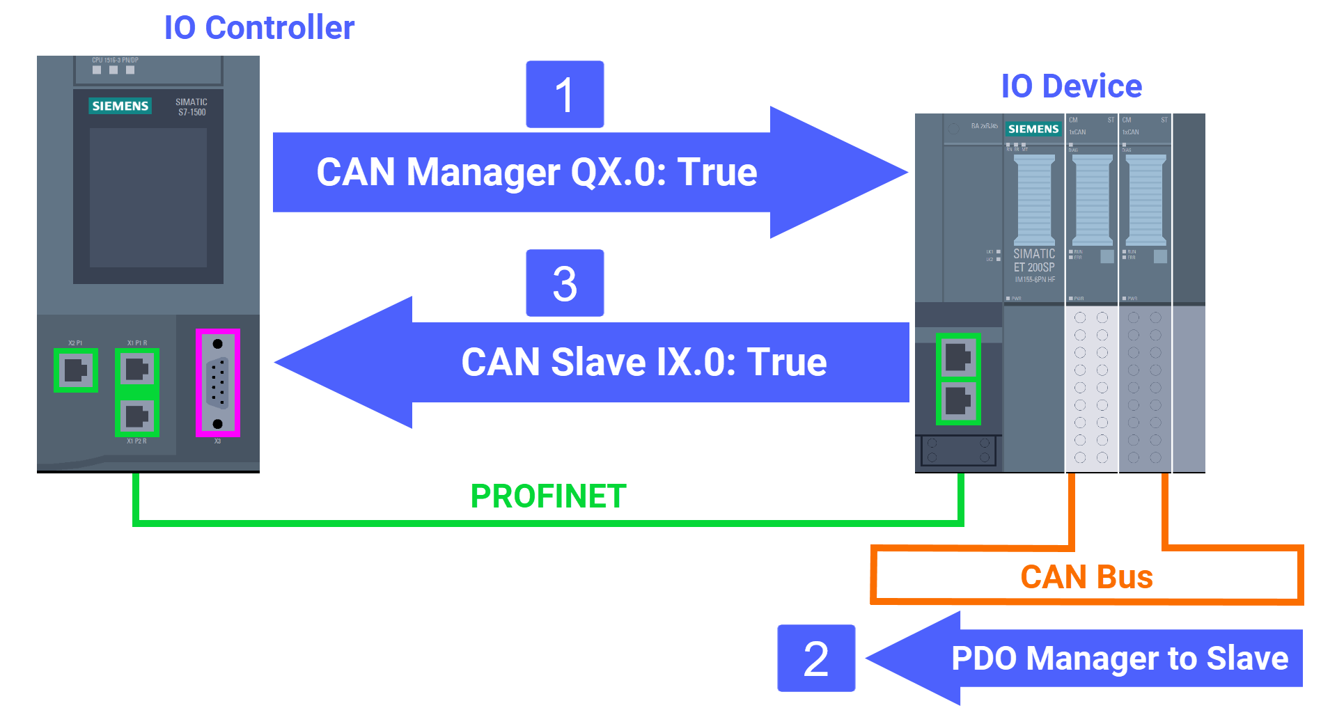
Shift your focus to the data exchange process over PROFINET and how the CAN modules communicate with each other. The 'CM CAN Manager' module receives IO data written by the S7-1500 controller. The 'CM CAN Manager' module forwards the data as a PDO message across the CAN bus. The IO data on the 'CM CAN Slave' module is updated upon receiving the PDO message, and the SIMATIC S7 controller, in turn, reads it.
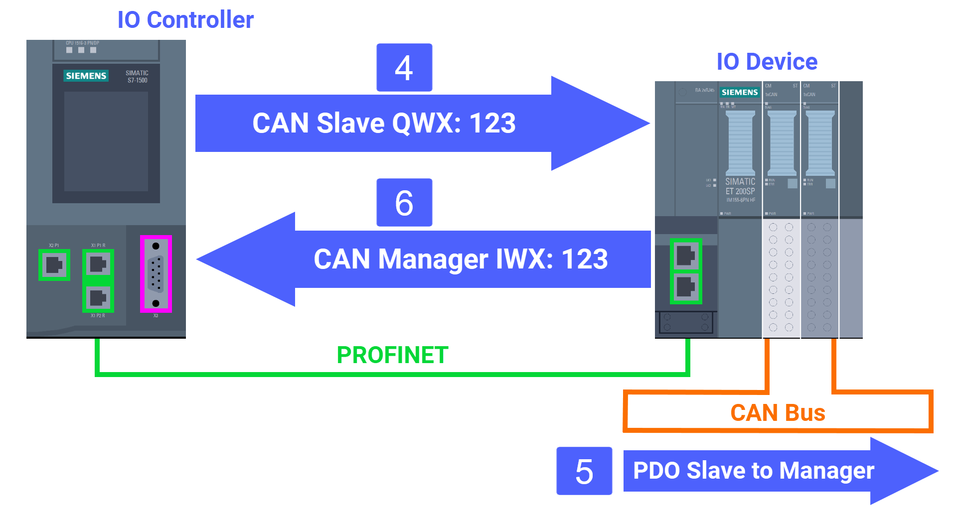
IO data now gets written from the S7 controller into the 'CM CAN Slave' module. A PDO message containing the data is sent out from the 'CM CAN Slave' module onto the CAN bus. After picking up the PDO message and refreshing its IO data, the 'CM CAN Manager' module has that data read back by the S7 controller.
CAN Modules Wiring
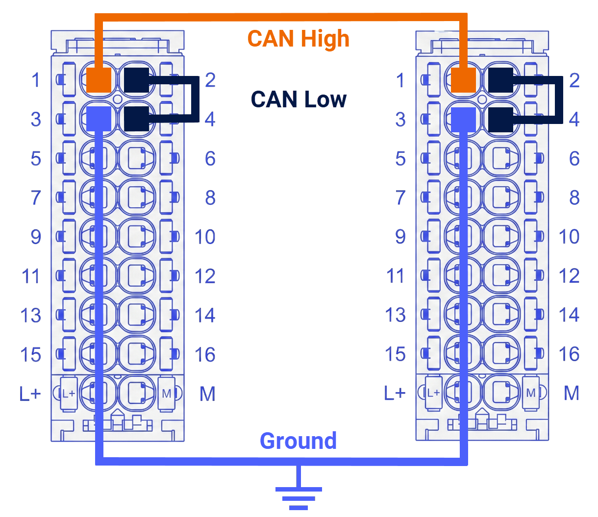
The wiring between the CAN bus signals and the CAN modules' BaseUnits is laid out in Figure 4.1.
Program Blocks
Take a look at Figure 5.1 to see how the entire project's program structure is organized.
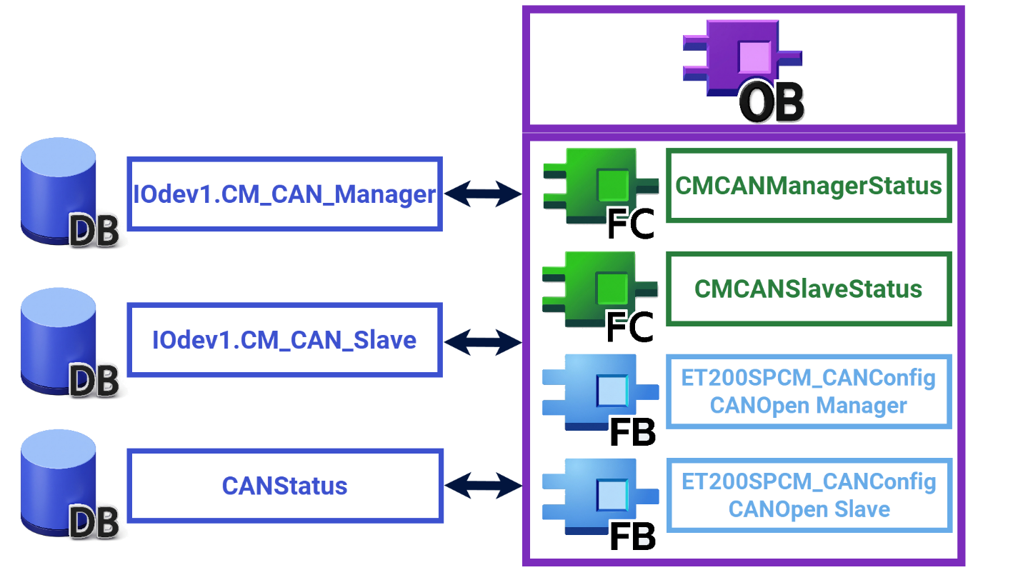
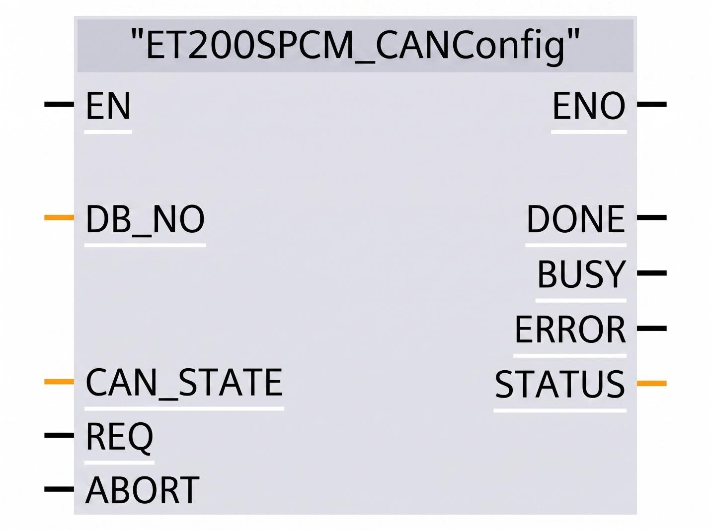
To exchange payload and configuration data, the program uses the 'ET200SPCM_CANConfig' function block.
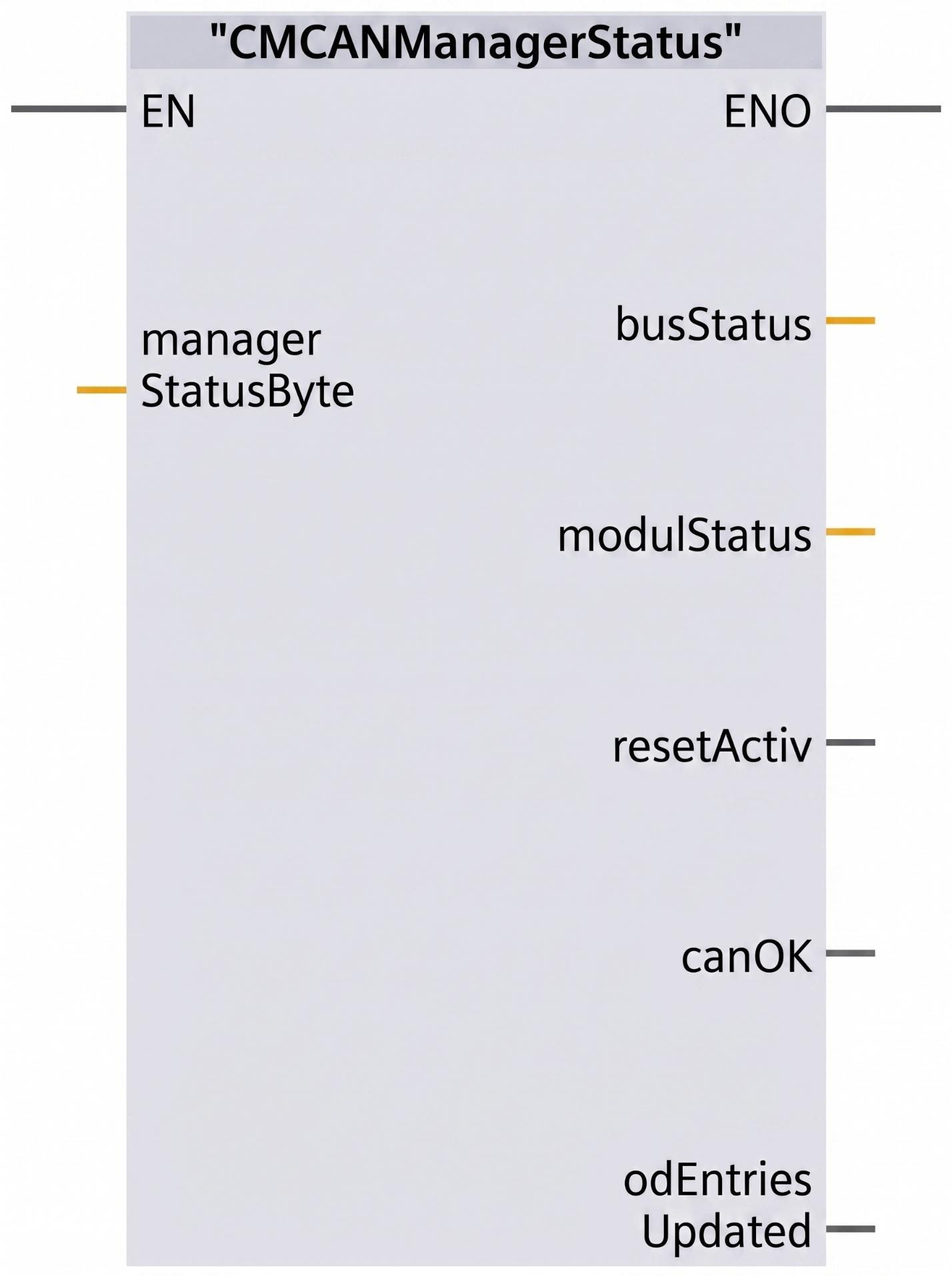
The 'CMCANManagerStatus' function is used here too, working alongside the 'ET200SPCM_CANConfig' function block. This function was developed in-house as a proprietary solution. Diagnosing the 'CM CAN Manager' module and the CAN bus falls under what this function does.
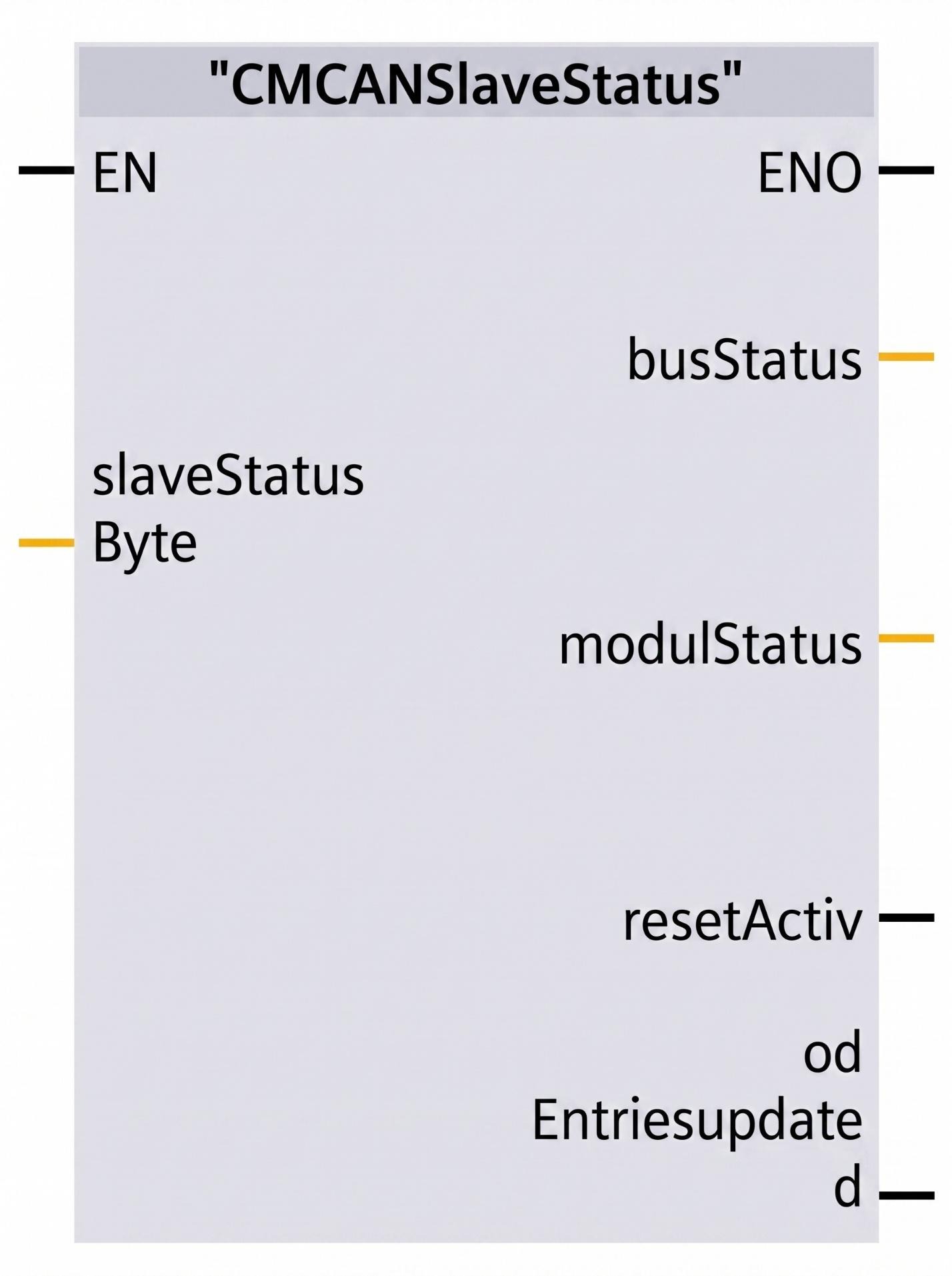
The program also relies on a function called 'CMCANSlaveStatus'. This function, too, was developed as a proprietary solution. Diagnosing the 'CAN Slave' module and the CAN bus falls under its responsibilities.
CAN Modules Configuration
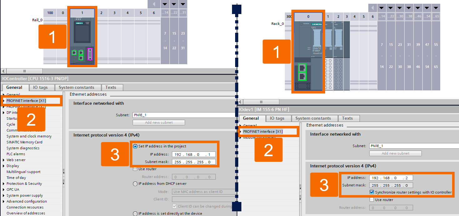
The steps that matter most for setting up the CAN modules as CANopen Slave and Manager are laid out in this section. Begin the process by setting up the CAN module as a CANopen Slave. You'll need to open a new project and add an S7-1500 CPU along with an ET 200SP IM 155-6 PN HF module.
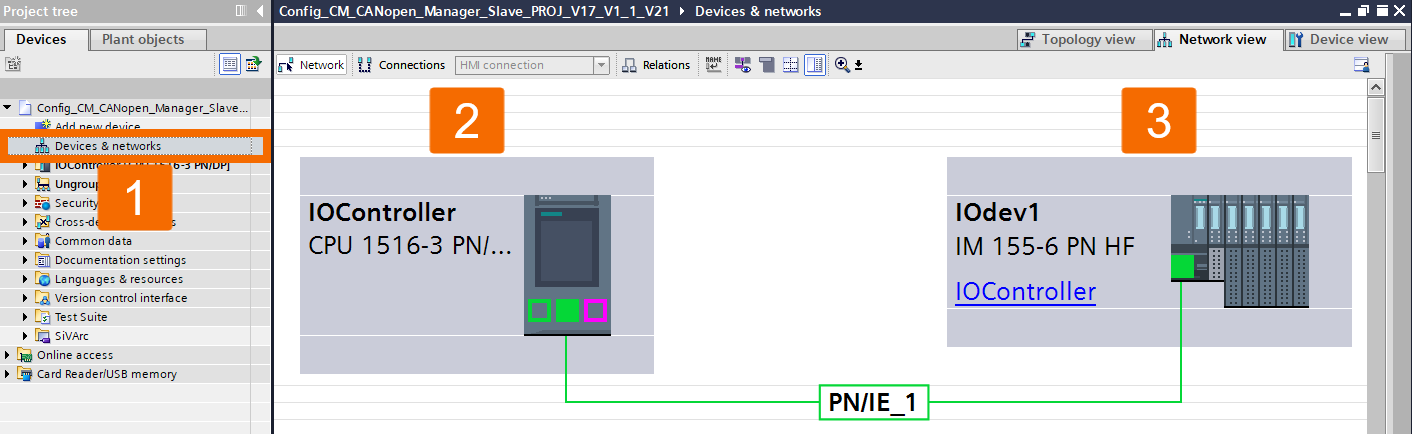
Update the modules' IP addresses so they align with your application's requirements.
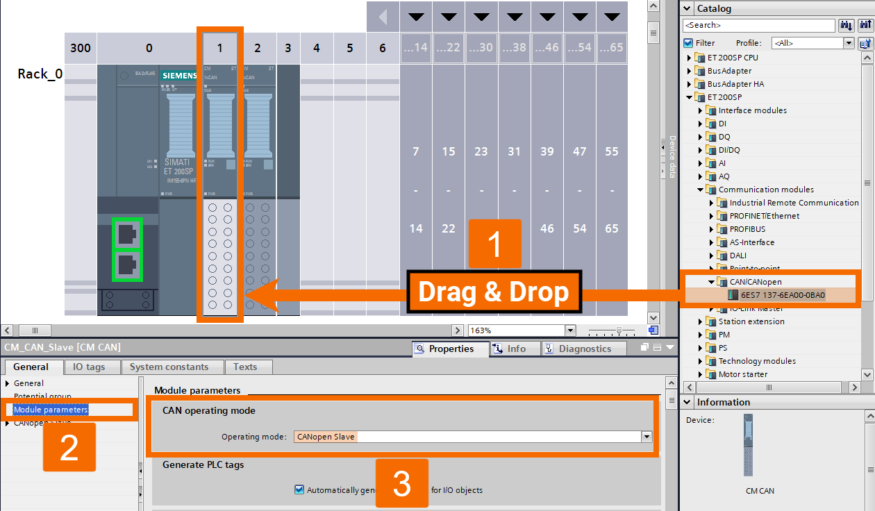
Drag the CM CANopen module from the catalog and drop it onto the ET 200SP in the hardware configuration. Set the module's operating mode to 'CANopen Slave'.
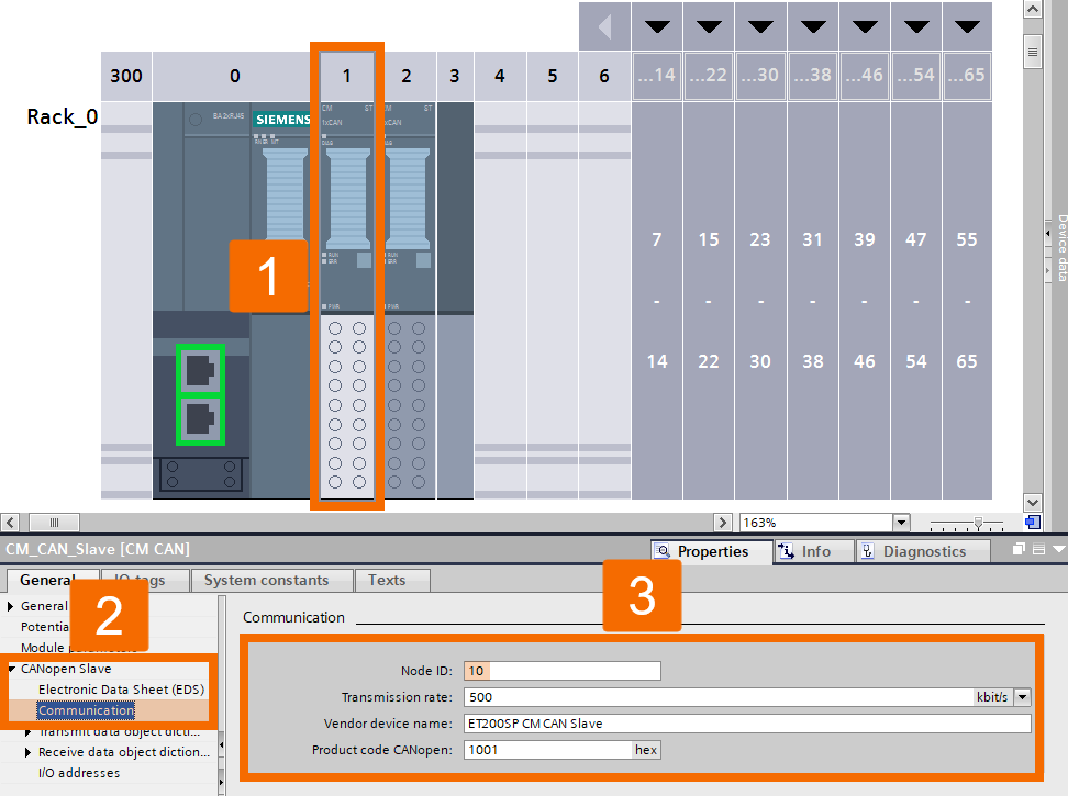
Handle communication configuration at this step.
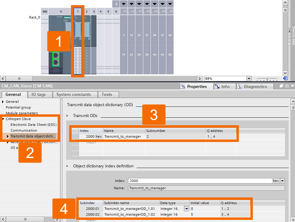
Establish the send-side data for the CM CANopen Slave, including its Name, Subnumber, Q address, and index definition, as it goes to the CM CANopen Manager.
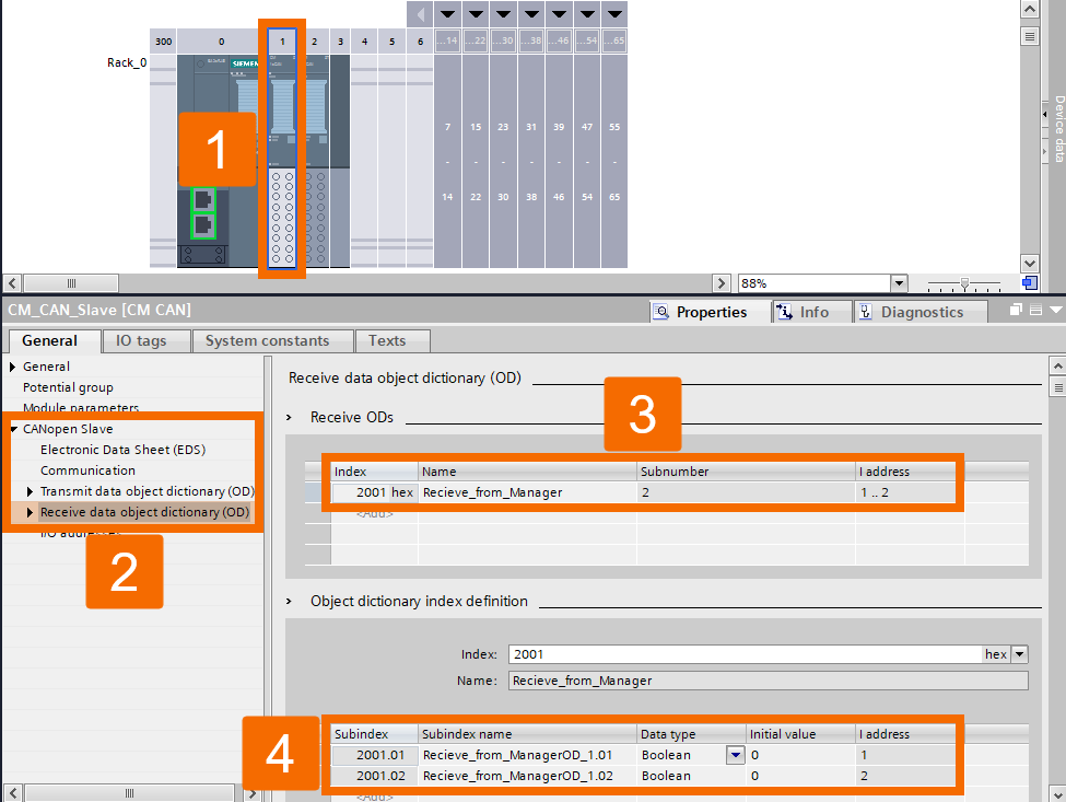
Establish the receive-side data for the CM CANopen Slave, including Name, Subnumber, Q address, and index definition, as it comes from the CM CANopen Manager.
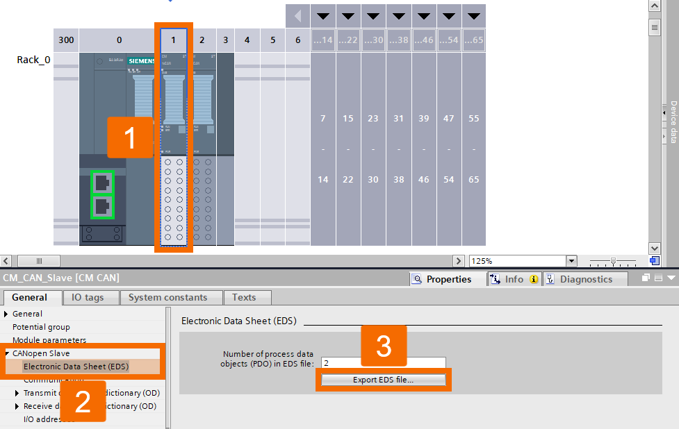
Take the CM CANopen Slave configuration and export it in EDS format.
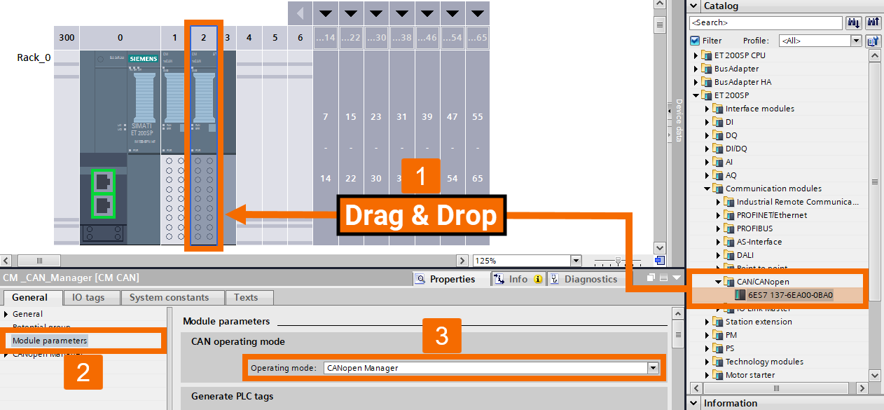
Time to set up the other CAN module in the CANopen Manager role. Repeat the same drag-and-drop step, placing the CM CANopen module onto the ET 200SP in hardware configuration. Set the operating mode on this module to 'CANopen Manager'.
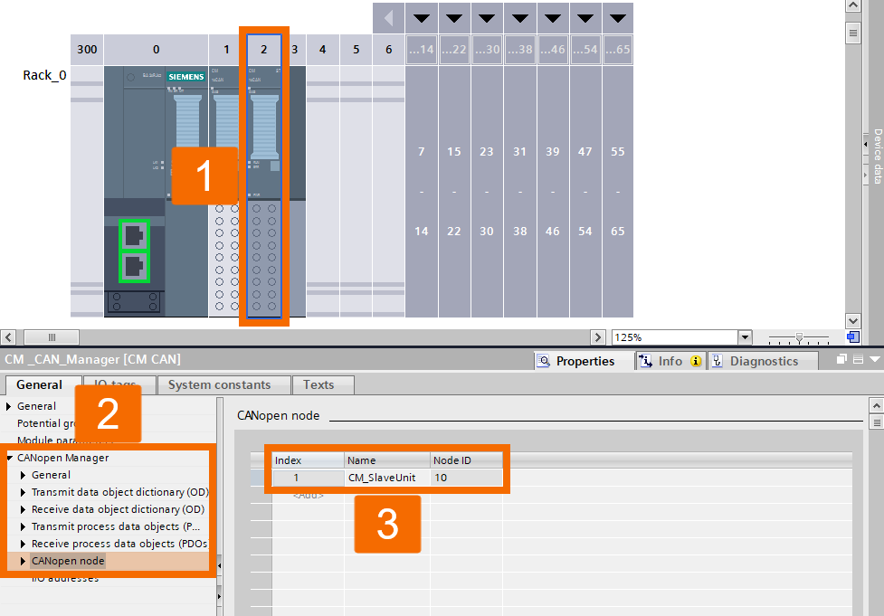
You'll need to create the CANopen Manager's node next.
Import the EDS file containing the CM CANopen Slave's configuration into the Manager setup.
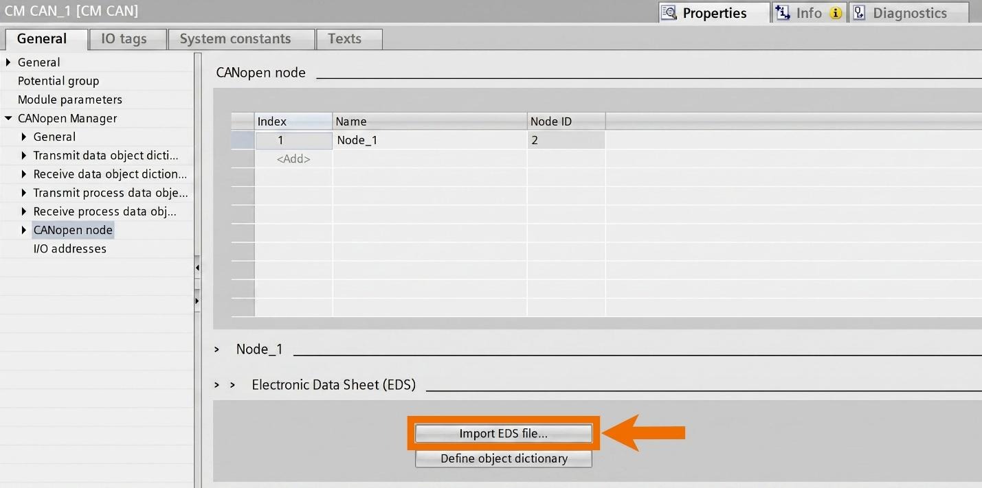
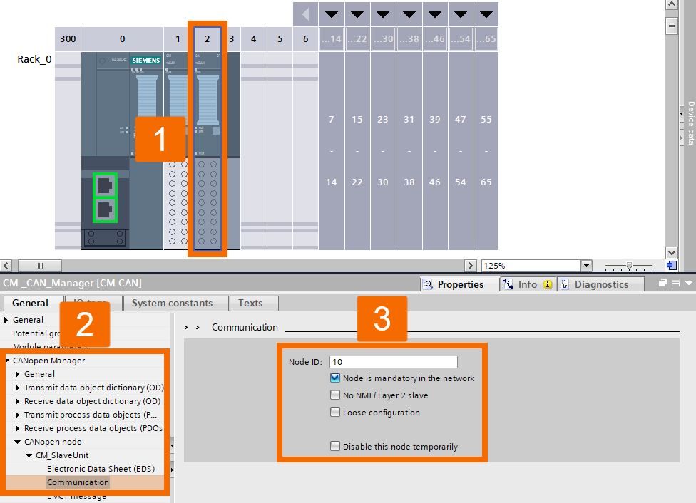
Give the CM CANopen Slave its "Node ID" setting.
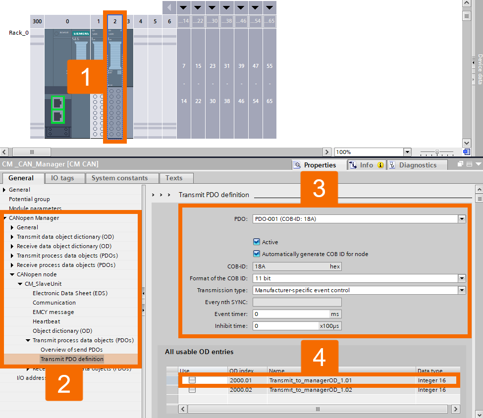
Set up the outgoing data path, defining what the CM CANopen Slave sends to the Manager module across the CAN bus.
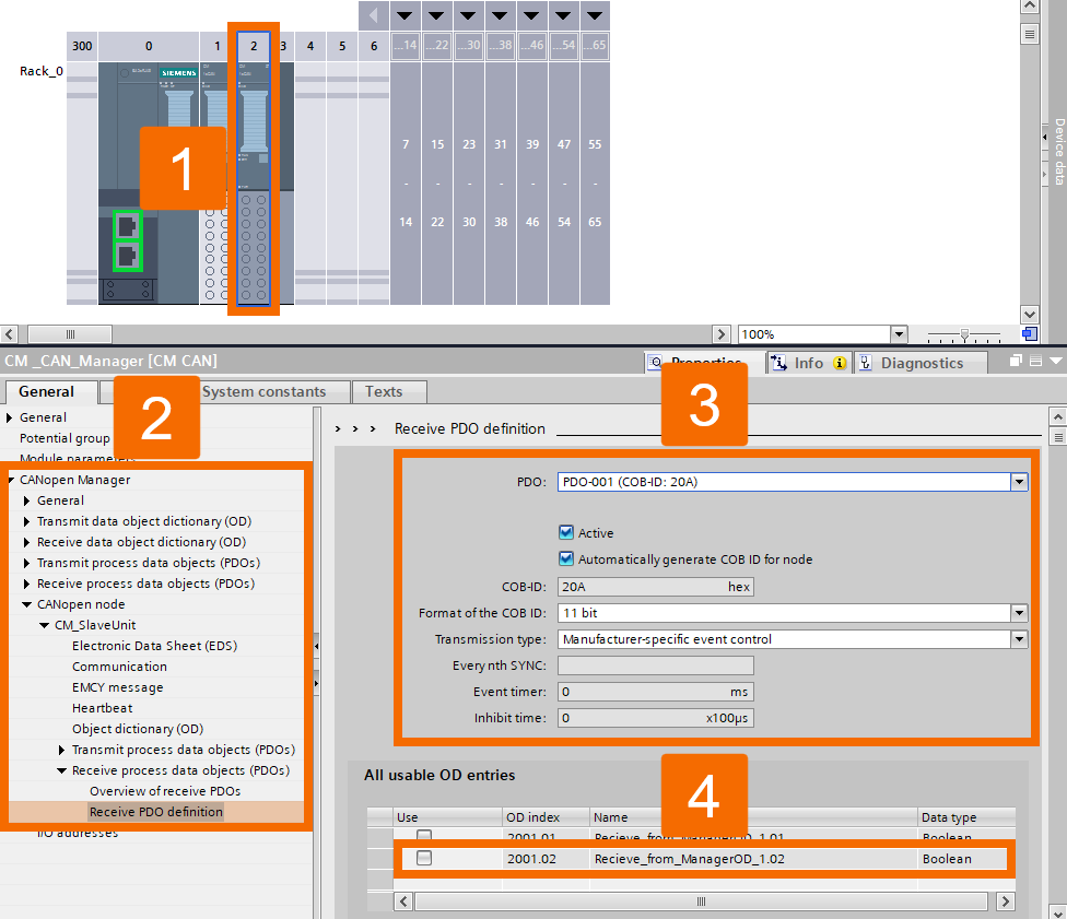
You'll also need to define the data the Slave module receives from the CM CANopen Manager over the CAN bus.
Make sure the transmit data OD (Object Dictionary) you create in the Manager module corresponds exactly with the Slave's receive data.
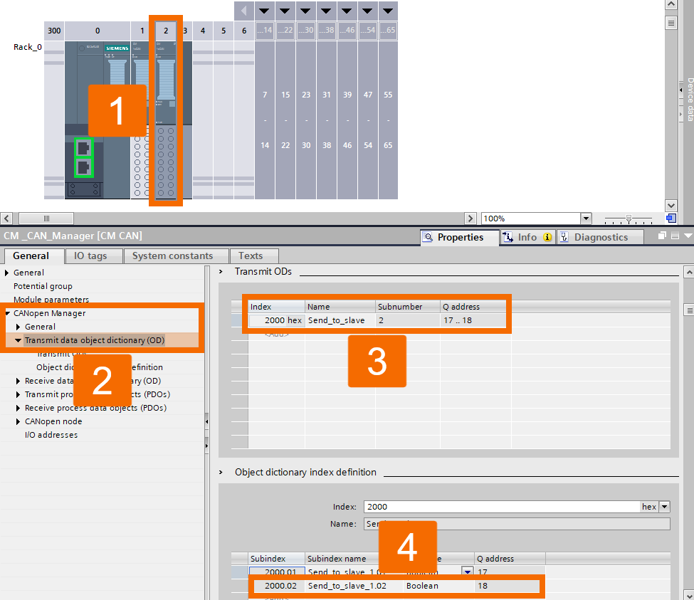
Configure the outgoing PDOs, which are the transmit process data, in the Manager slave.
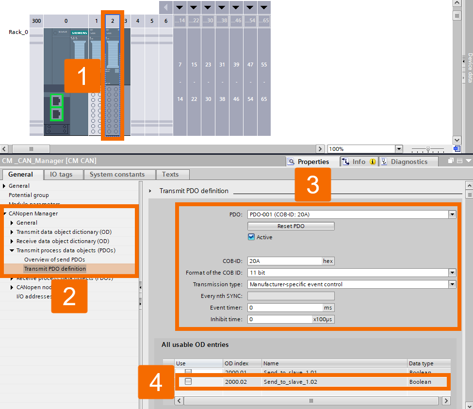
The right way to configure the PDOs is shown in Figure 6.16.
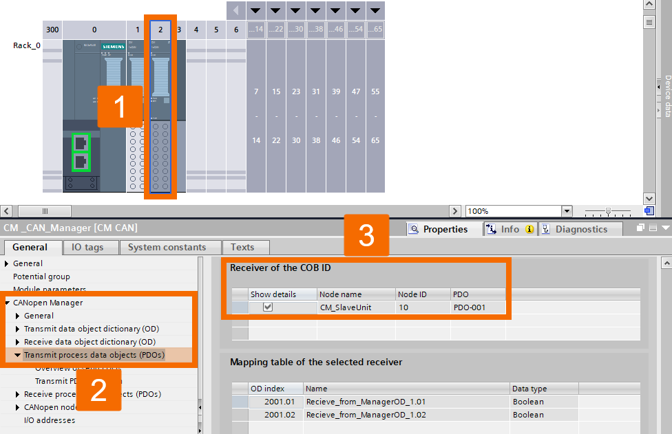
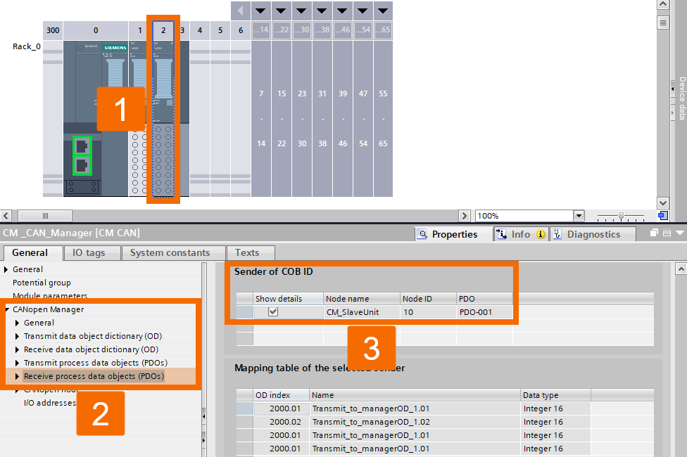
Configure the Manager's receive-side ODs so they line up exactly with the transmit process data objects from CM CANopen Slave.
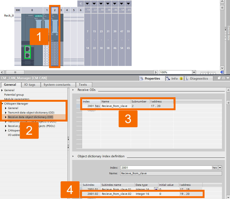
Configure the CM CANopen Manager's outgoing process data objects, known as PDOs.
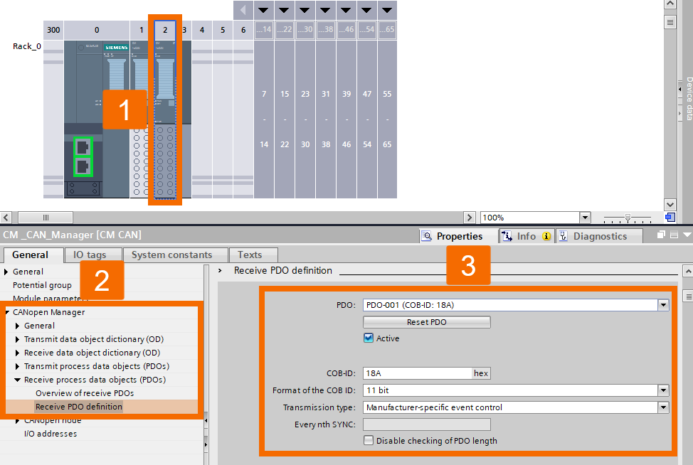
Check Figure 6.19 to make sure your PDO settings are correct.
Program Blocks Integration
Within a single program cycle, the 'ET200SPCM_CANConfig' function block gets called twice in the user program to handle configuration for both 'CM CAN Manager' and 'CM CAN Slave' modules.
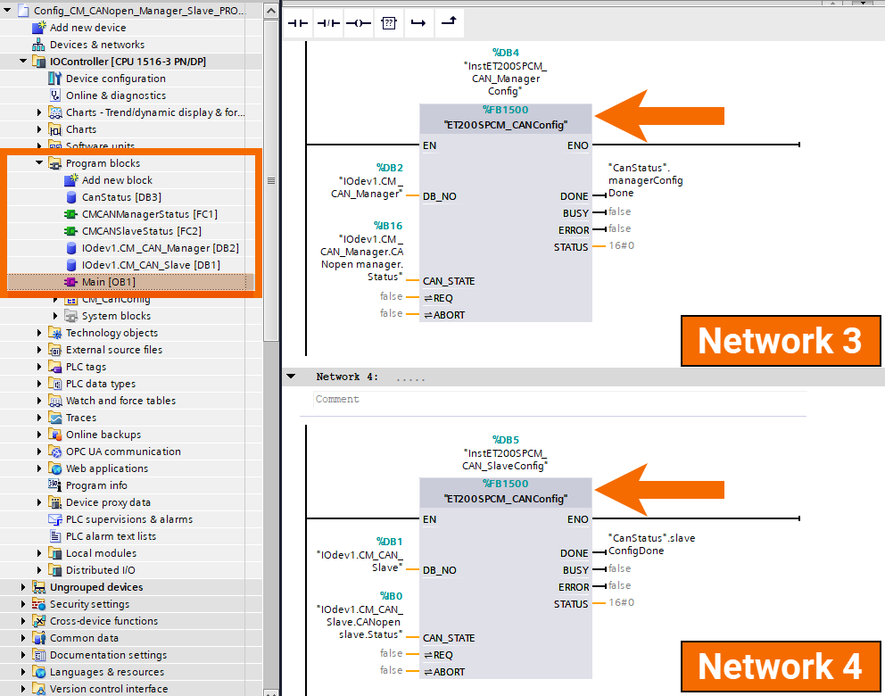
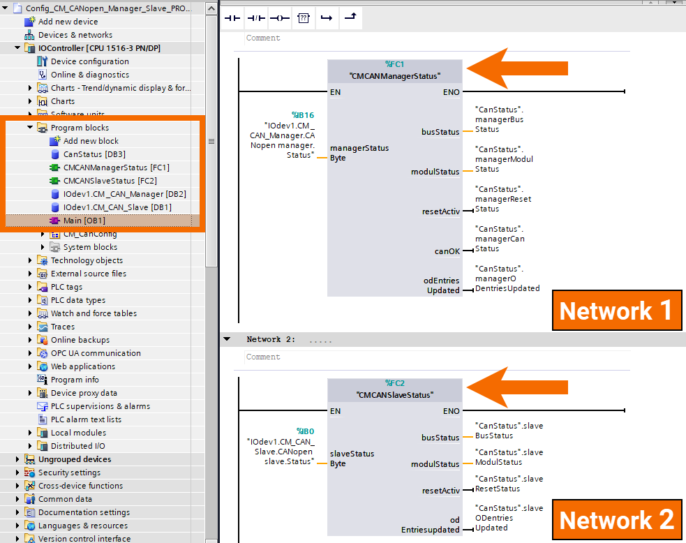
In addition to the 'ET200SPCM_CANConfig' function block, you'll also find the 'CMCANManagerStatus' and 'CMCANSlaveStatus' functions in use. These were developed internally as proprietary solutions. The objective of these blocks is to provide diagnostic coverage for the CAN bus and for both CAN modules, Manager and Slave. In OB1, both the 'CMCANManagerStatus' and the 'CMCANSlaveStatus' functions execute before the 'ET200SPCM_CANConfig' function blocks run.
Operation
After compiling the program, select the CPU in the project tree and then press the 'Download' button on the top toolbar to transfer the project to the controller.
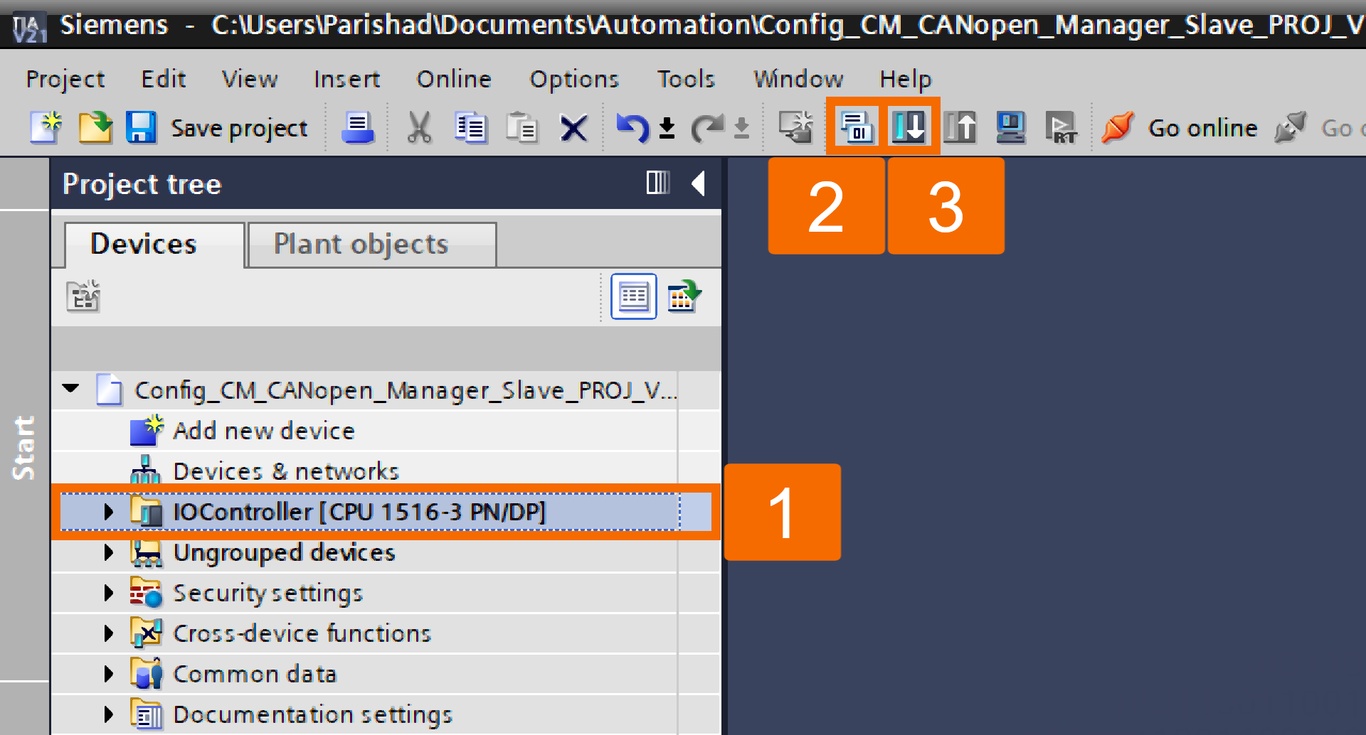
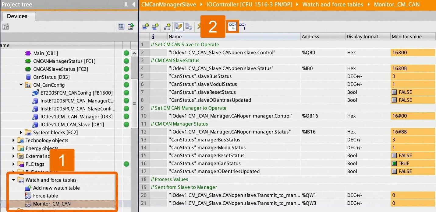
Coming up next, you'll see how to send values both ways. First, from 'CM CAN Manager' to 'CM CAN Slave', and then back again from the Slave module to the Manager module. In TIA Portal, pull up the 'Monitor_CM_CAN' watch table and switch to online mode.
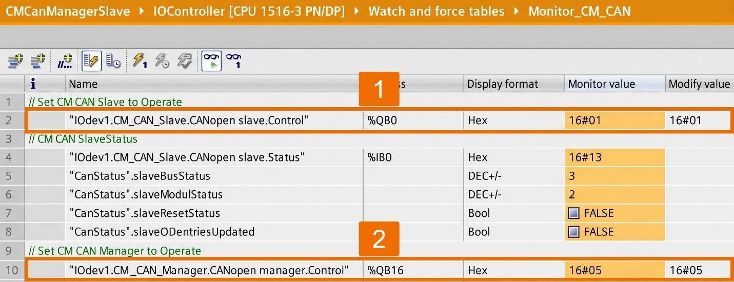
Assign the value of 16#01 to 'IOdev1.CM_CAN_Slave.CANopen_slave.Control' and the value of 16#05 to 'IOdev1.CM_CAN_Manager.CANopen_manager.Control'.
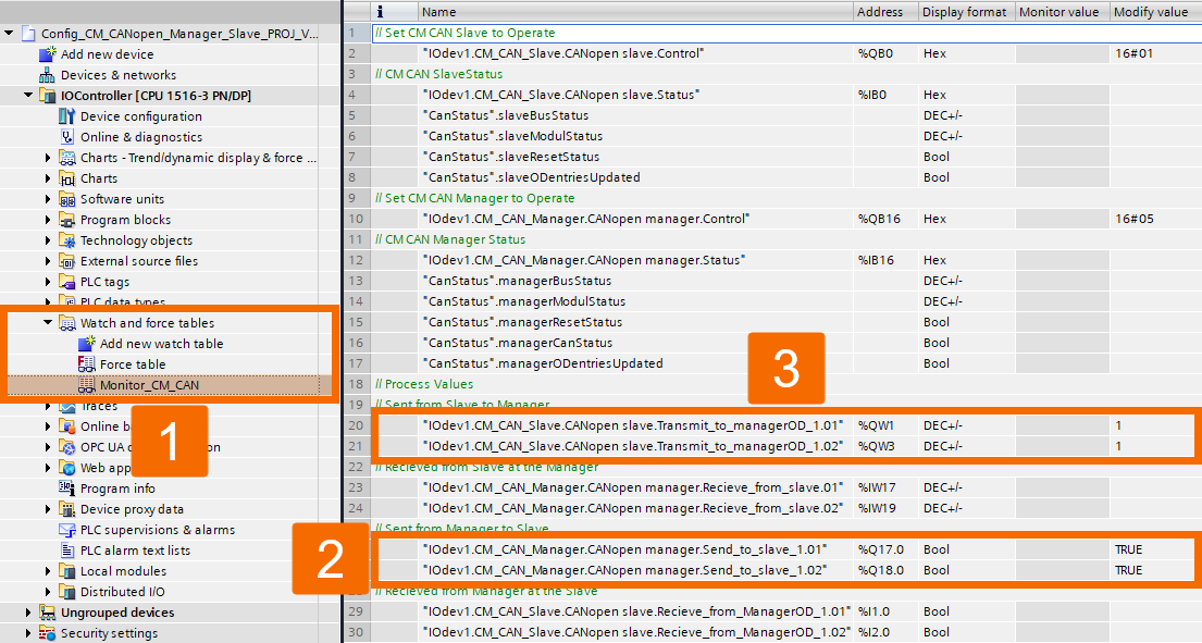
Assign 'True' to both Q17.0 and Q18.0. As a result of this step, 'CM CAN Manager' sends its value to 'CM CAN Slave', confirmed when 'CanStatus.slaveODentriesUpdated' switches to 'True'. Choose a decimal value of your own and apply it to QW1 and QW3. As a result, the Slave module sends its value to the Manager module, confirmed when the 'CanStatus.managerODentriesUpdated' entry switches to 'True'.
Conclusion
In conclusion, you have learned how the CM CAN Manager and Slave modules coordinate through the 'ET200SPCM_CANConfig' function block to exchange payload and configuration data with the S7 controller. You've seen the full startup sequence, from 'Not Configured' through 'PreOperational' to 'Operational' and how PDO messages travel across the CAN bus in both directions. You also walked through configuring both modules in TIA Portal, exporting and importing the EDS file, aligning transmit and receive Object Dictionary entries, and using the 'CMCANManagerStatus' and 'CMCANSlaveStatus' functions for diagnostics. Finally, you tested the setup live using the 'Monitor_CM_CAN' watch table to confirm data exchange.


