

Encoder Setup on the S7-1200 G2 Using the Onboard HSC

Introduction
If you've ever needed encoder feedback on an S7-1200 G2 but didn't want to spend on a dedicated Technology Module, you already know the frustration. The onboard High Speed Counter (HSC) is right there, yet by default it won't talk to your Technology Objects. As a result, print-mark positioning, synchronous motion, and probe-based correction feel out of reach without extra hardware. That's exactly the gap the LHSCTO library closes, and it's worth understanding if you want lean, cost-effective machine designs. Whether you're chasing tighter print registration or want your onboard I/O to pull more weight, this is a skill that pays off on real panels, not just in theory.
Overview
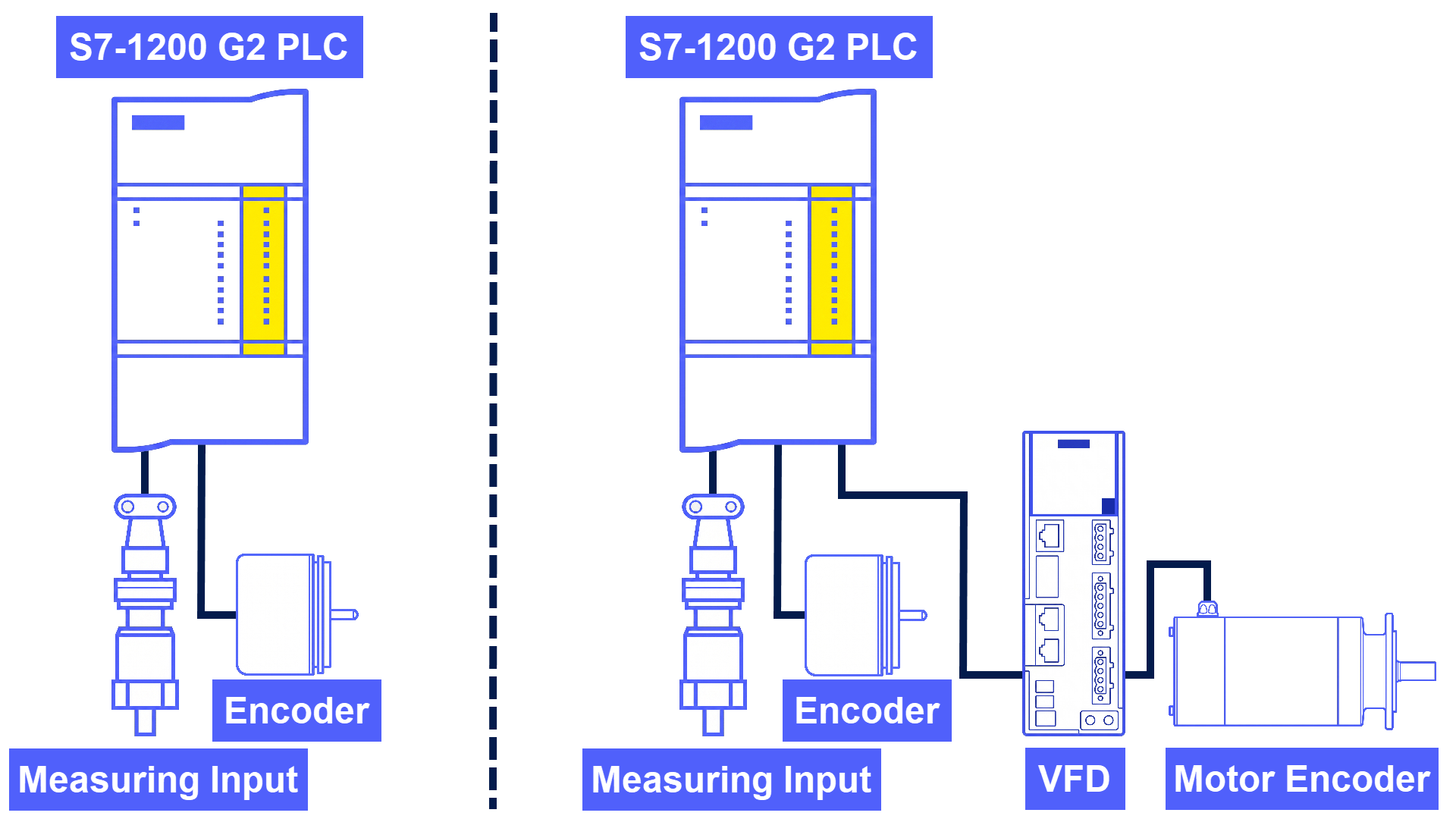
It's common in simple automation applications to skip Profibus encoders and extra Technology Modules altogether, using the built-in peripherals instead. The S7-1200 G2 PLC, in its default state, doesn't allow an encoder or measuring probe to be linked to Technology Objects via the onboard High Speed Counter (HSC). What the LHSCTO library does, which you can download here, is establish a connection path for an encoder and measuring probe into specific Technology Objects via the onboard HSC. Whether you need print-mark-based positioning or print mark correction, this applies to synchronous applications. There are two configurations demonstrated in this application example. In the first case, an encoder acts as the leading value, paired with a measuring probe. The second setup involves an encoder serving as the positioning feedback encoder, plus a measuring probe.
Working Principle
Figure 2.1 breaks down the working principle behind the configuration that pairs an encoder with a measuring probe.
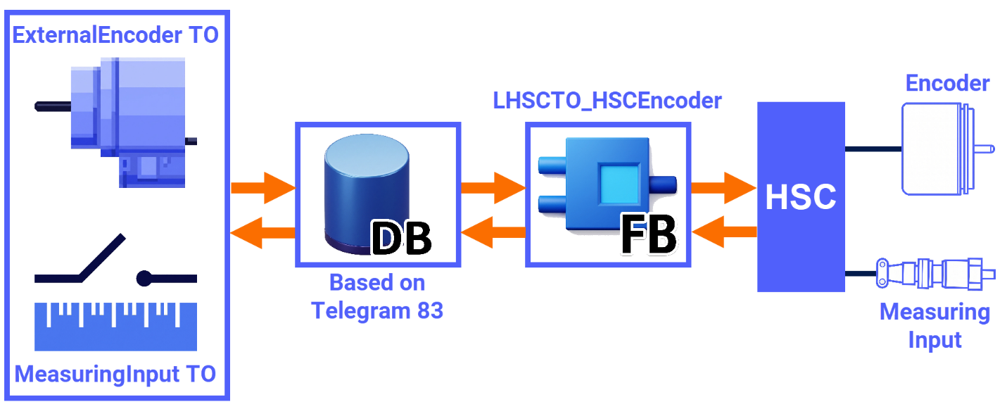
Figure 2.2 is a visual breakdown of how an encoder configuration operates as the positioning feedback, alongside a measuring probe.
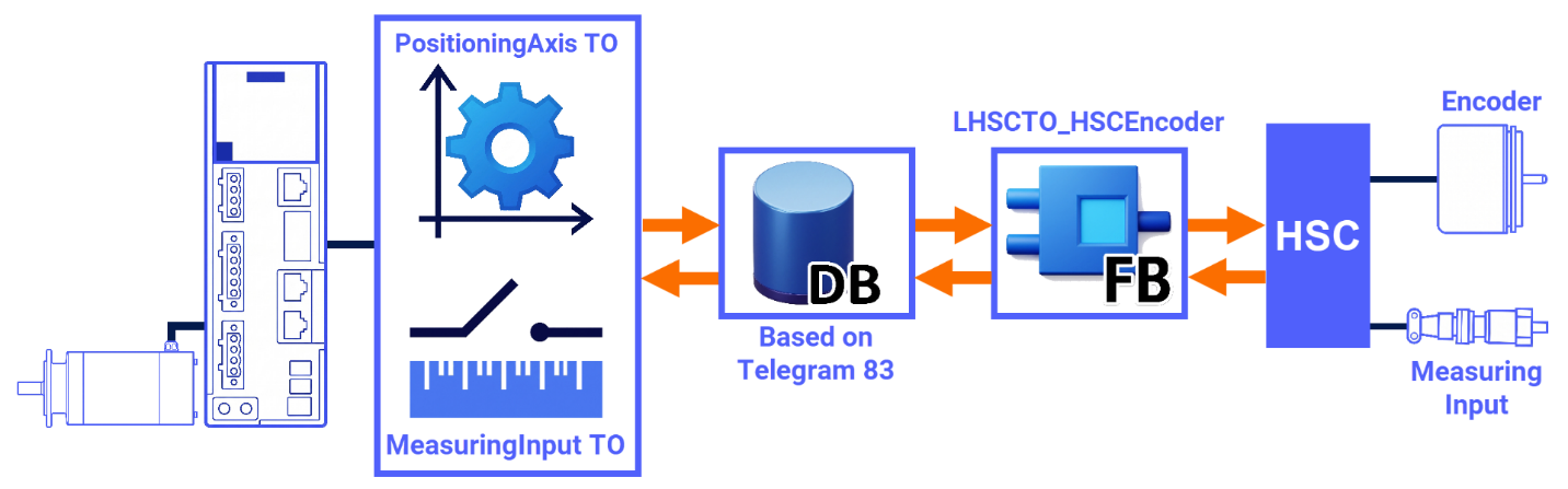
Through the LHSCTO_HSCEncoder block, the onboard HSC gets tied to the telegram 83 data block interface. As a result, the TOs (Technical Objects) can communicate with the encoder and measuring probe over the HSC.
Encoder & Probe Configuration
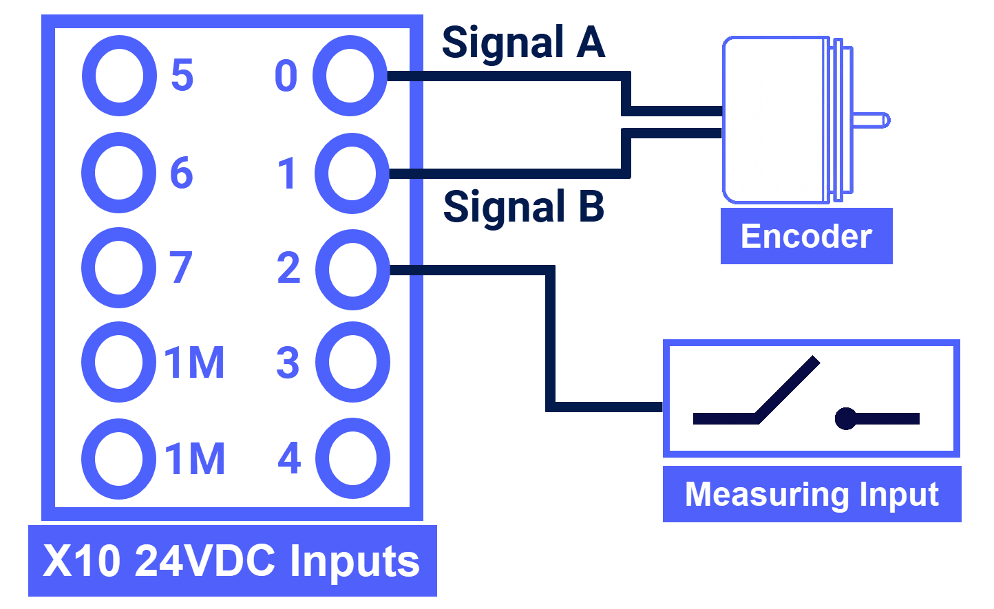
If you need to wire the encoder's A/B phases and the measuring probe to the SIMATIC S7-1200 G2 digital inputs, look at Figure 3.1 for guidance. A 24-volt signal level is the only one the S7-1200 G2 PLC will accept from encoders.
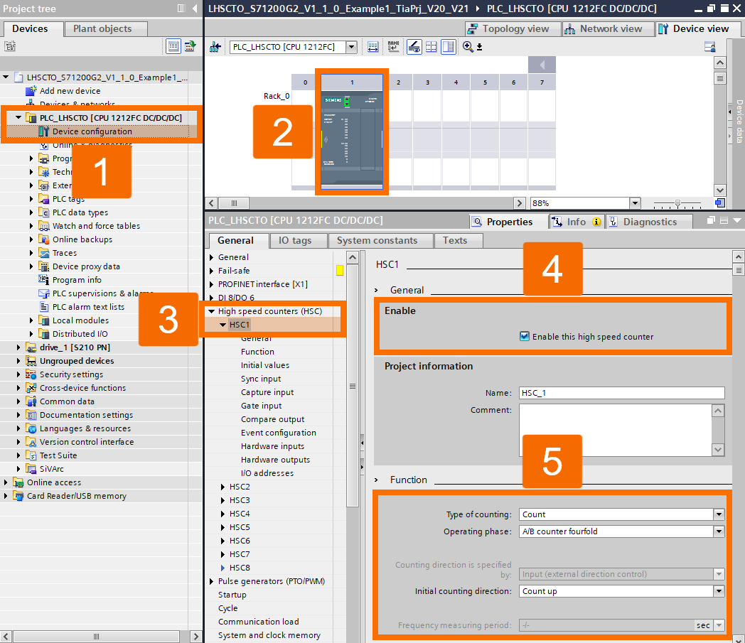
HSC1 is set up to work with an encoder here, matching the configuration shown in Figure 3.2.
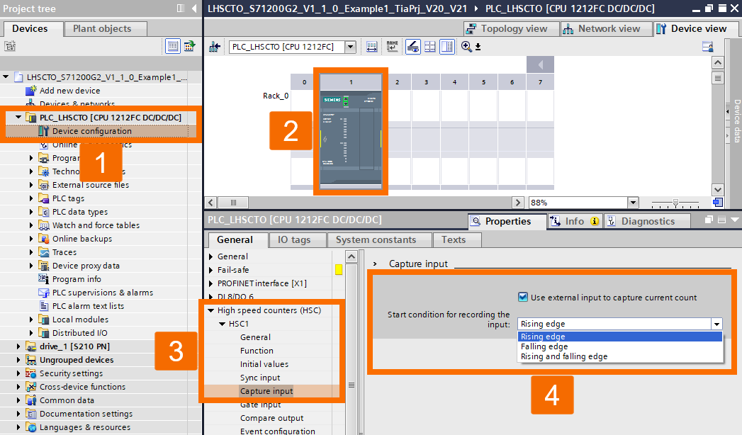
Configuration of the 'Capture Input' should match what's shown in Figure 3.3. A rising edge from the sensor is what triggers the input. Different modes are available if you want to change this behavior.
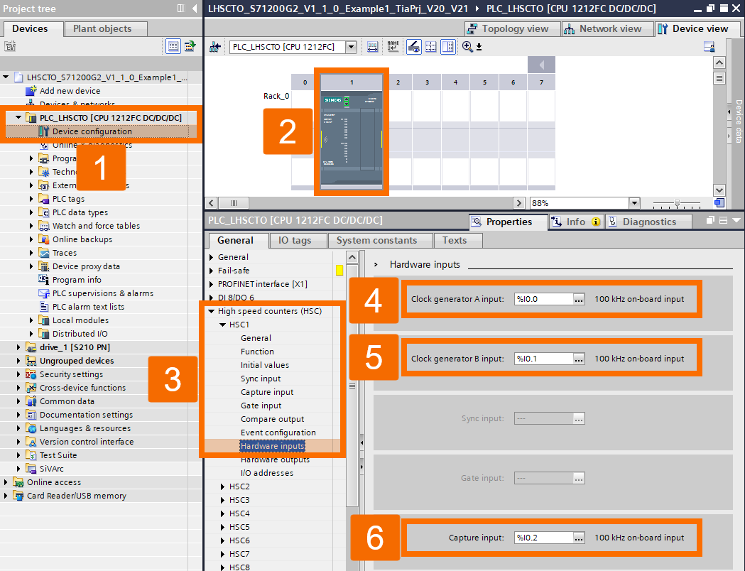
The onboard hardware inputs tied to the HSC being used also require proper configuration beforehand. You can see the HSC1 configuration used in this example by checking Figure 3.4. Earlier wiring details are what guide the selection of the number of inputs.
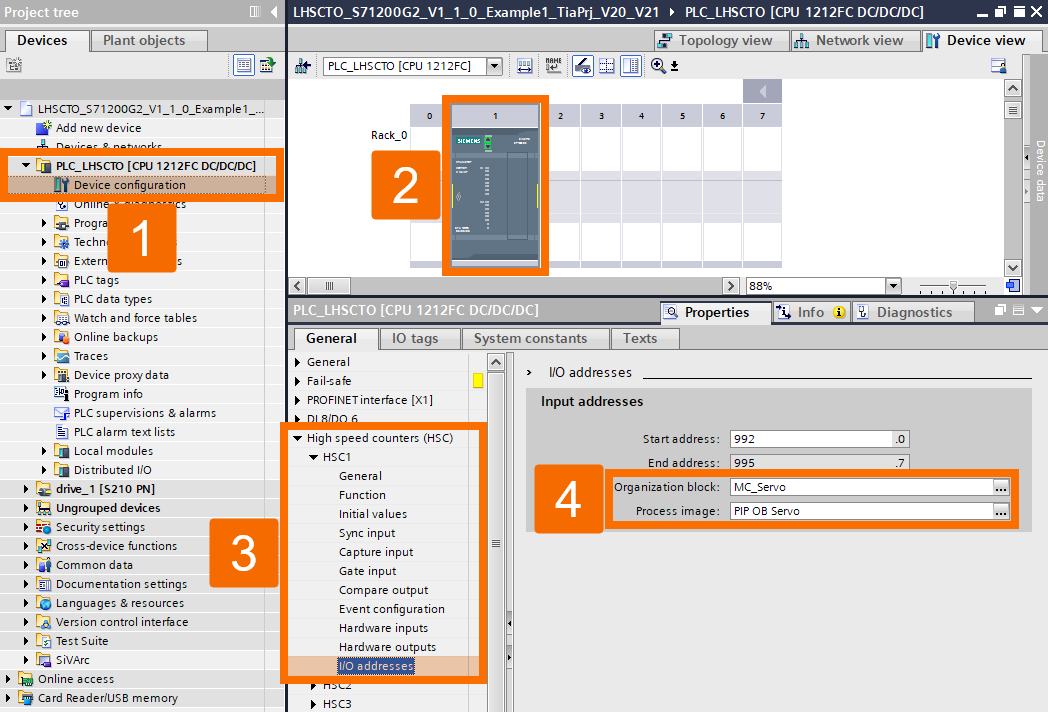
The 'MC_Servo' organization block needs to have the input addresses of the used HSC assigned to it. Figure 3.5 shows a visual of the configuration used here.
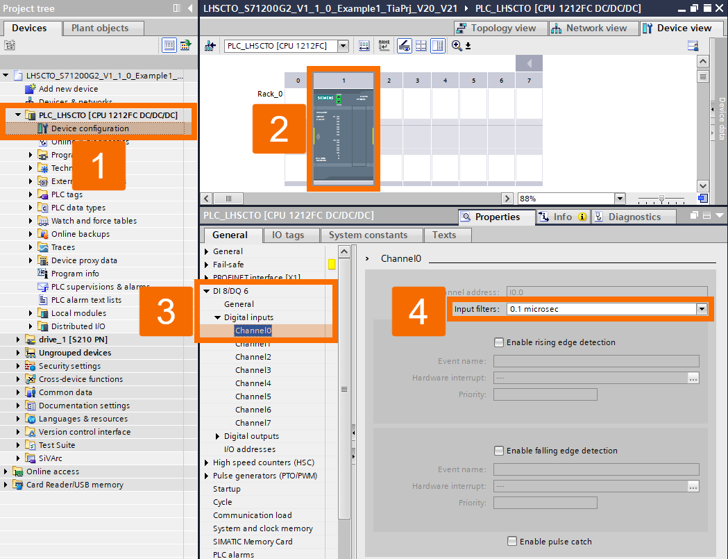
Following the layout in Figure 3.6, in this application example, channels 0 through 7 each had their input filters adjusted. The digital input channels currently in use require their input filters to be changed to just 0.1 microseconds. Signal changes might slip past undetected if the input filter time is set too long.
Technology Objects Configuration
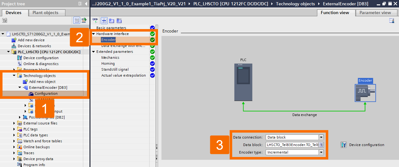
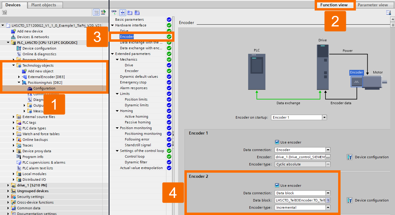
You'll need to create and configure Technology Objects according to whatever configuration is required. If you're working with the 'ExternalEncoder' Technology Object configuration, the encoder's data connection must be set up using a telegram-83-based data block, following what's shown in Figure 4.1.
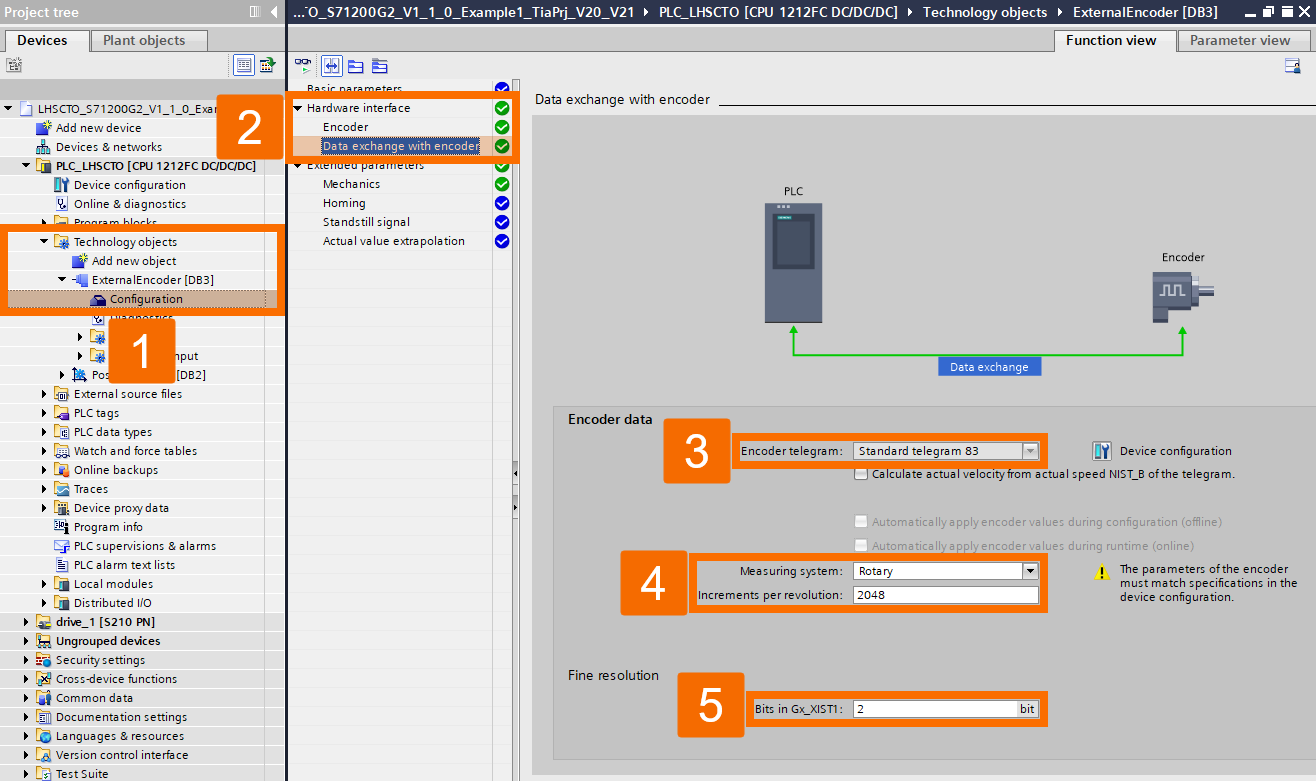
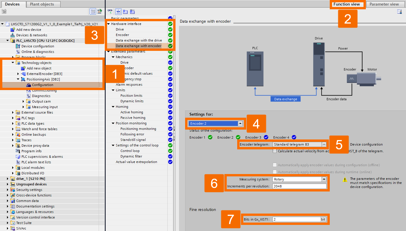
A rotatory measuring system rated at 2048 increments per revolution, combined with standard telegram 83, is used in this application project, as shown in Figure 4.2. With the HSC's A/B counter configured as fourfold, the 'Bits in Gx_XIST1' fine resolution setting comes out to 2, since multiplying by 4 corresponds exactly to a shift of 2 bits.
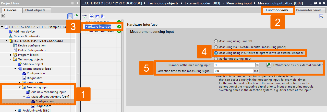
Whenever a measuring probe is required, it should be configured through the PROFIdrive telegram within the 'MeasuringInput' Technology Object, exactly as shown in Figure 4.3. A value of 1 for the 'Number of Measuring Probe' option maps directly to the HSC's recording input. No matter which specific hardware input address is configured in the HSC settings, the measuring probe's value stays fixed permanently at 1 when using an HSC.
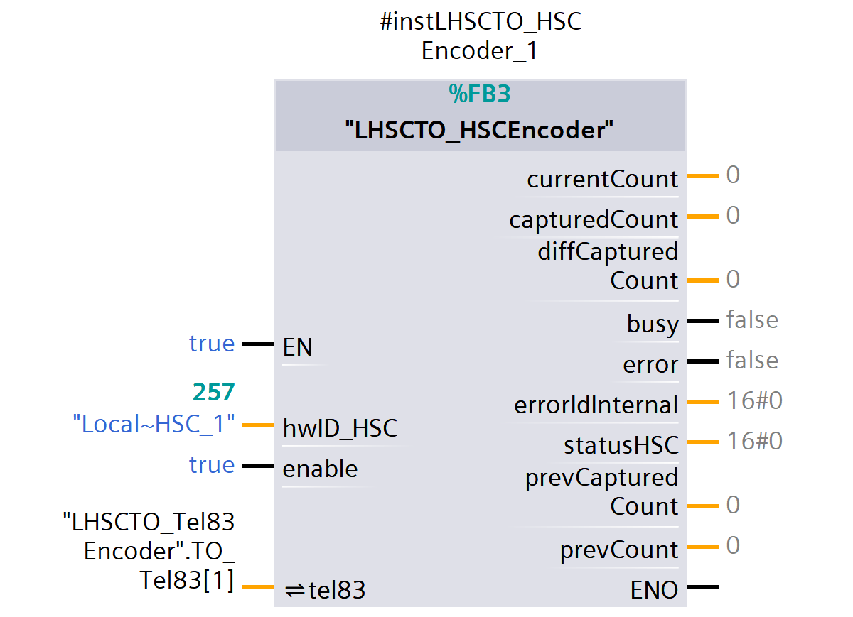
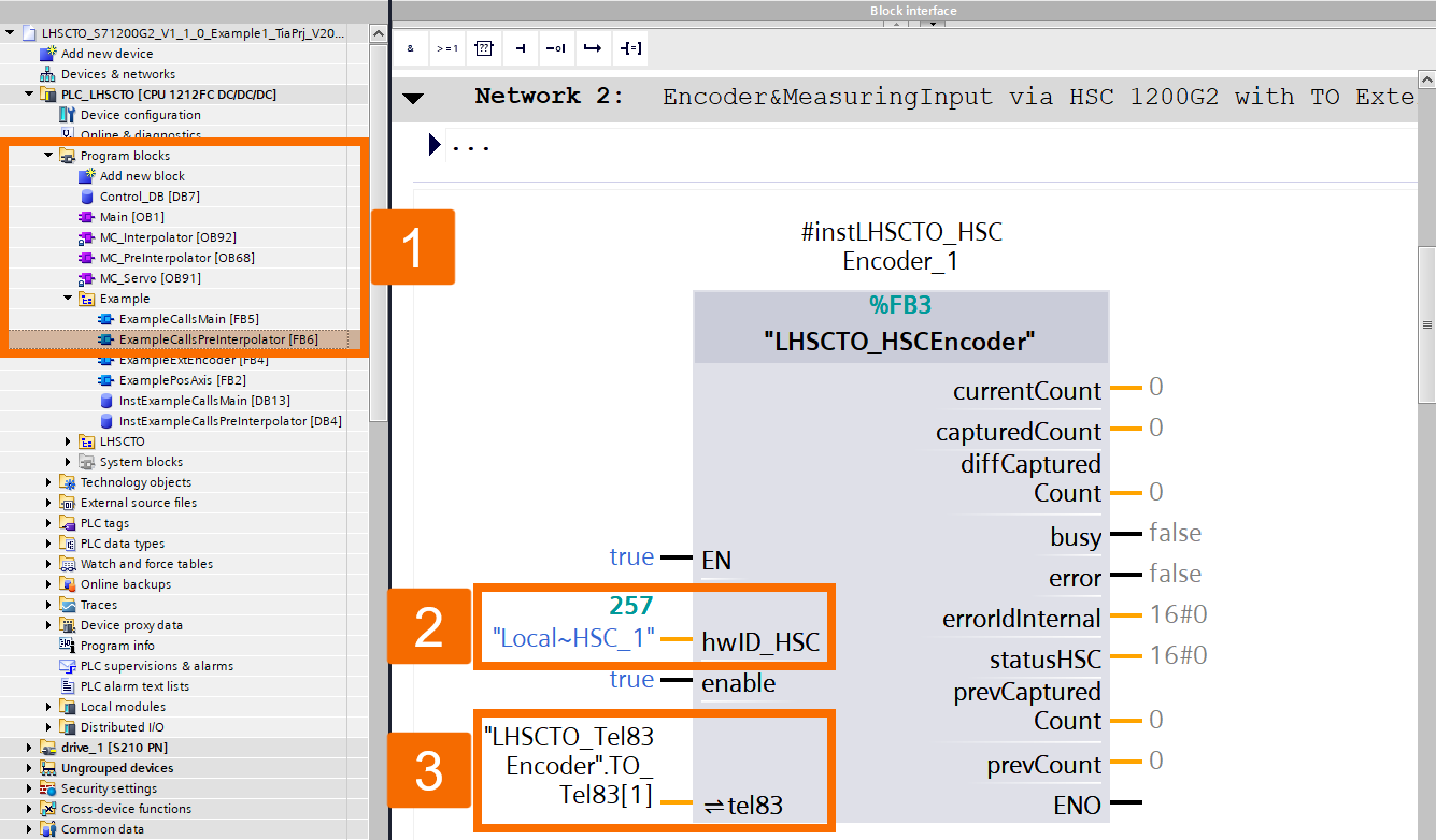
The 'LHSCTO_HSCEncoder' function block's 'hwID_HSC' input is assigned to the configured high-speed counter's system constant, as illustrated in Figure 4.4. That particular tel83-based data block ends up getting assigned to the 'tel83' InOut.
In the 'ExternalEncoder' Technology Object scenario, you will need to configure the encoder's data connection using a properly built telegram 83 data block, exactly as shown in Figure 4.5. This example has the encoder set up as 'Encoder 2'.
A rotatory measuring system rated at 2048 increments per revolution, combined with standard telegram 83, is used in this application project, as shown in Figure 4.6. With the HSC's A/B counter configured as fourfold, the 'Bits in Gx_XIST1' fine resolution setting comes out to 2, since multiplying by 4 corresponds exactly to a shift of 2 bits.
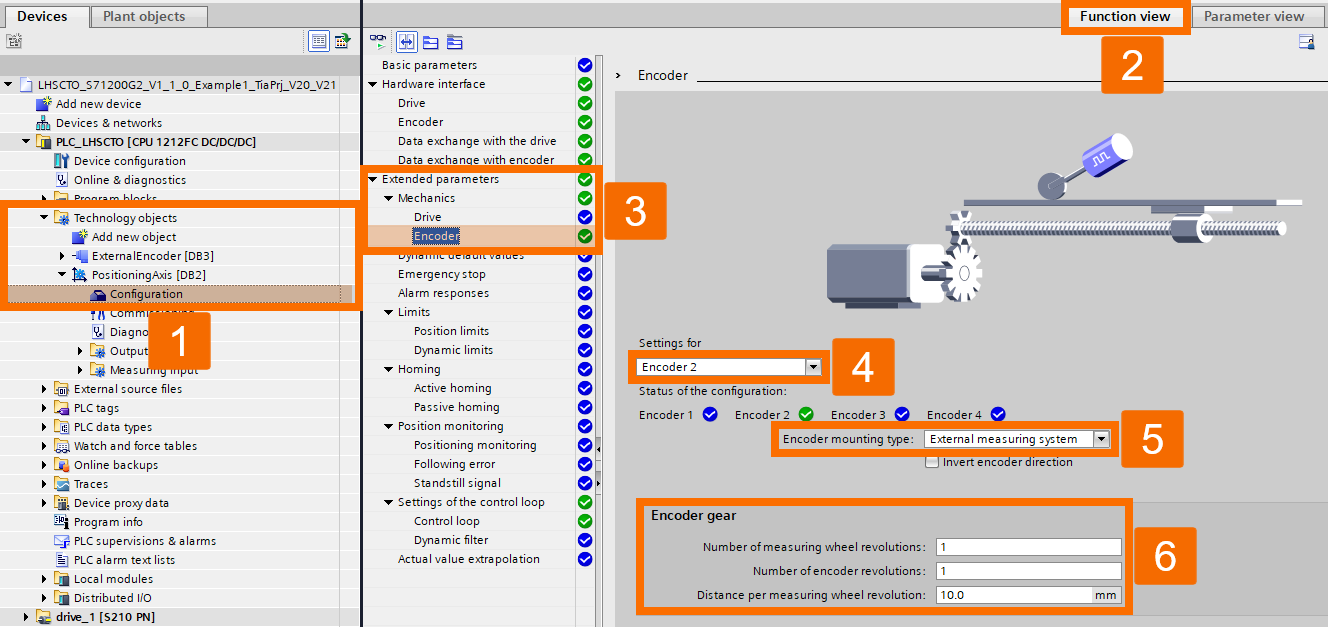
Defining the extended mechanical parameters for the external encoder has to align closely with the given system parameters. This particular configuration for this scenario is shown in Figure 4.7.
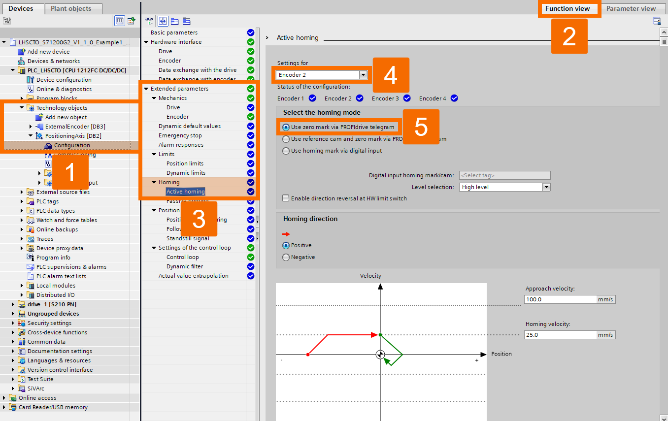
The 'PositioningAxis' Technology Object's external encoder supports active homing through a digital input, through a PROFIdrive telegram zero mark, or through a combination of a reference cam together with a PROFIdrive telegram zero mark. For 'Encoder 2' in this example, the PROFIdrive telegram zero mark is used, as shown in Figure 4.8. It gives the 'PositioningAxis' Technology Object the ability to treat its connected measuring probe, via HSC, as a zero mark.
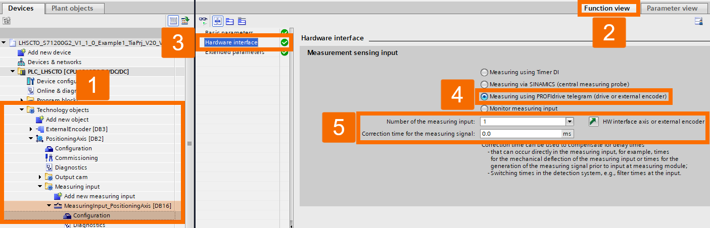
Whenever a measuring probe is required, it should be configured through the PROFIdrive telegram within the 'MeasuringInput' Technology Object, exactly as shown in Figure 4.9. Only when the 'Number of Measuring Probe' setting equals 1 does the onboard HSC actually support the measuring probe.
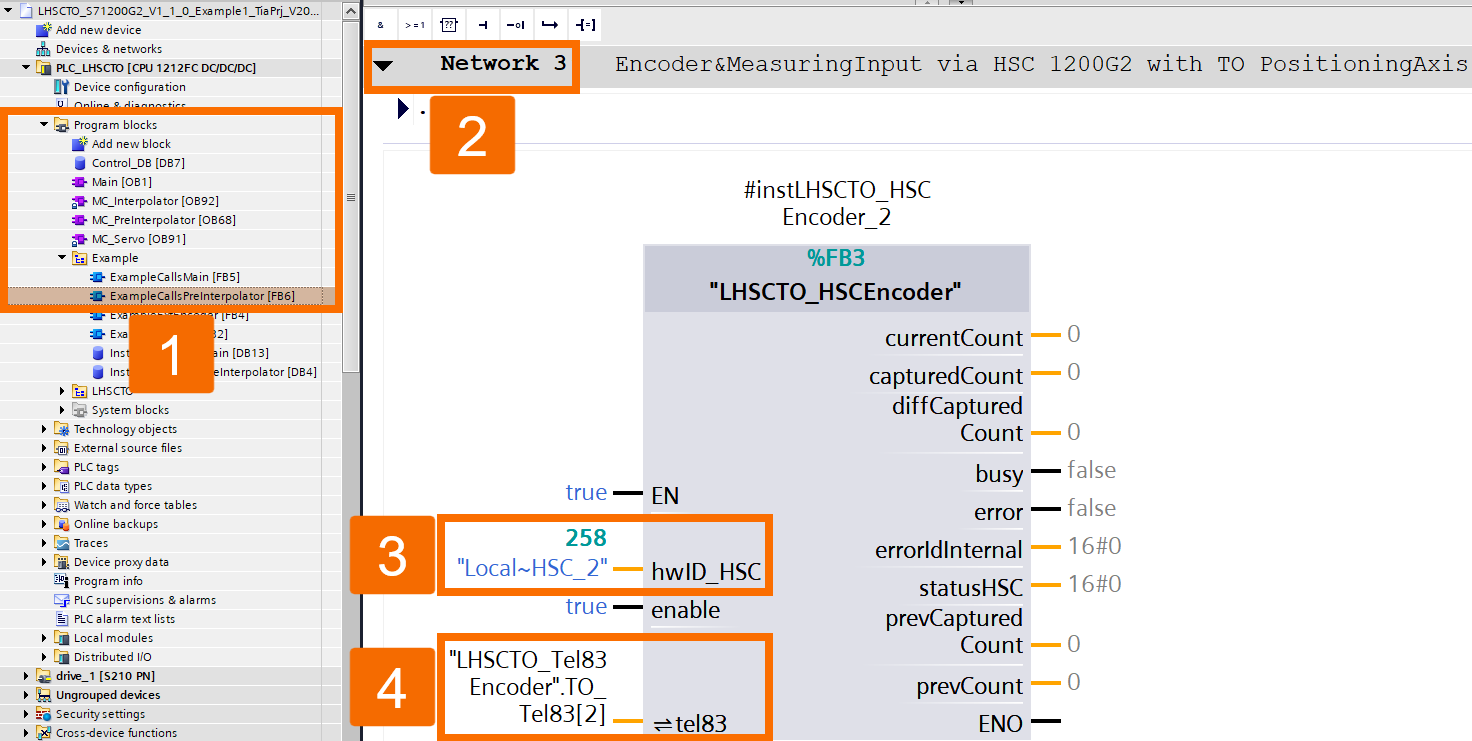
The 'LHSCTO_HSCEncoder' function block's 'hwID_HSC' input is assigned to the configured high-speed counter's system constant, as illustrated in Figure 4.10. That particular tel83-based data block ends up getting assigned to the 'tel83' InOut.
Operation
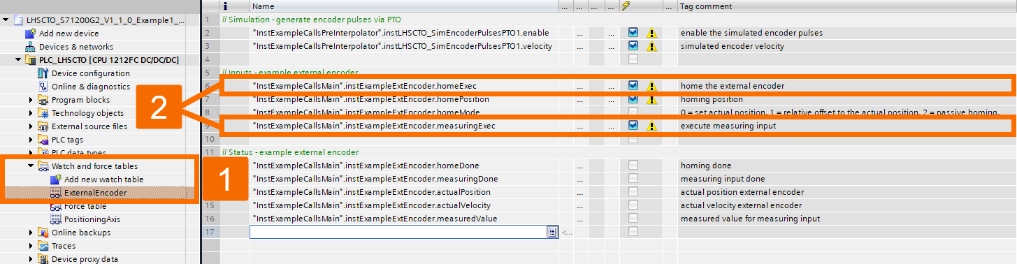
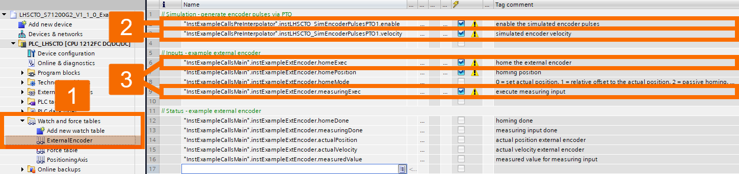
The watch table gives you a way to operate this example directly. Follow these steps to test the application example with an encoder set as the leading value. Homing or measuring input should be requested when it's needed.
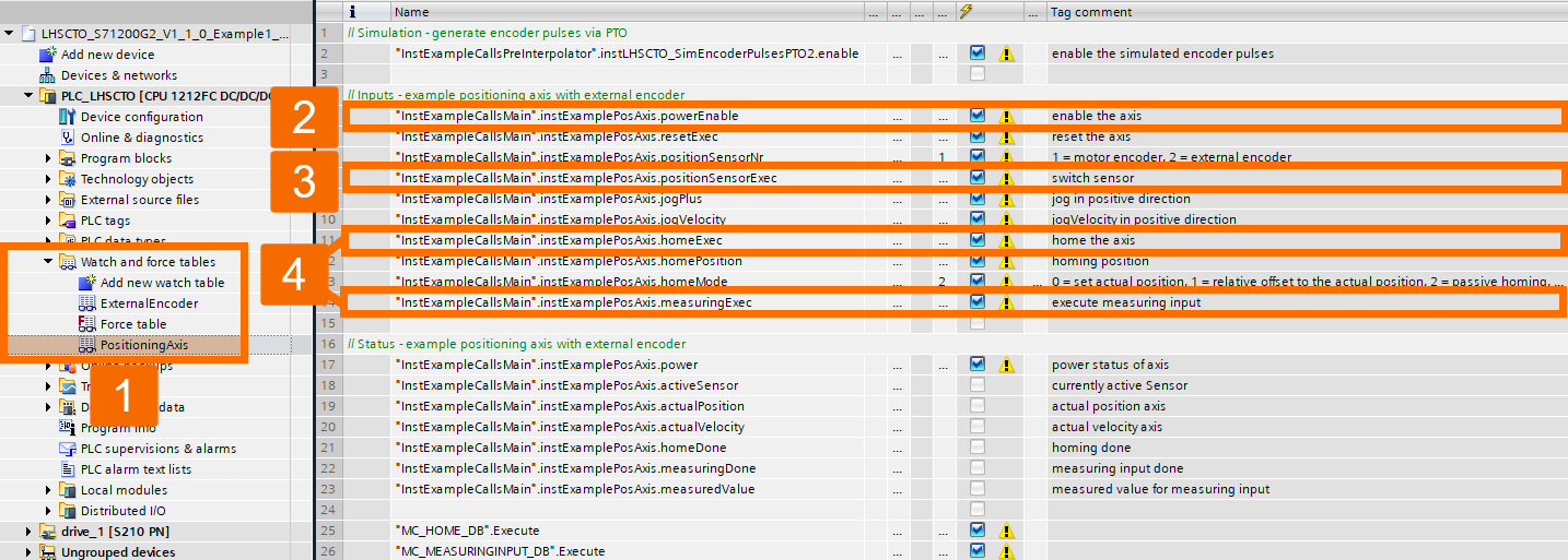
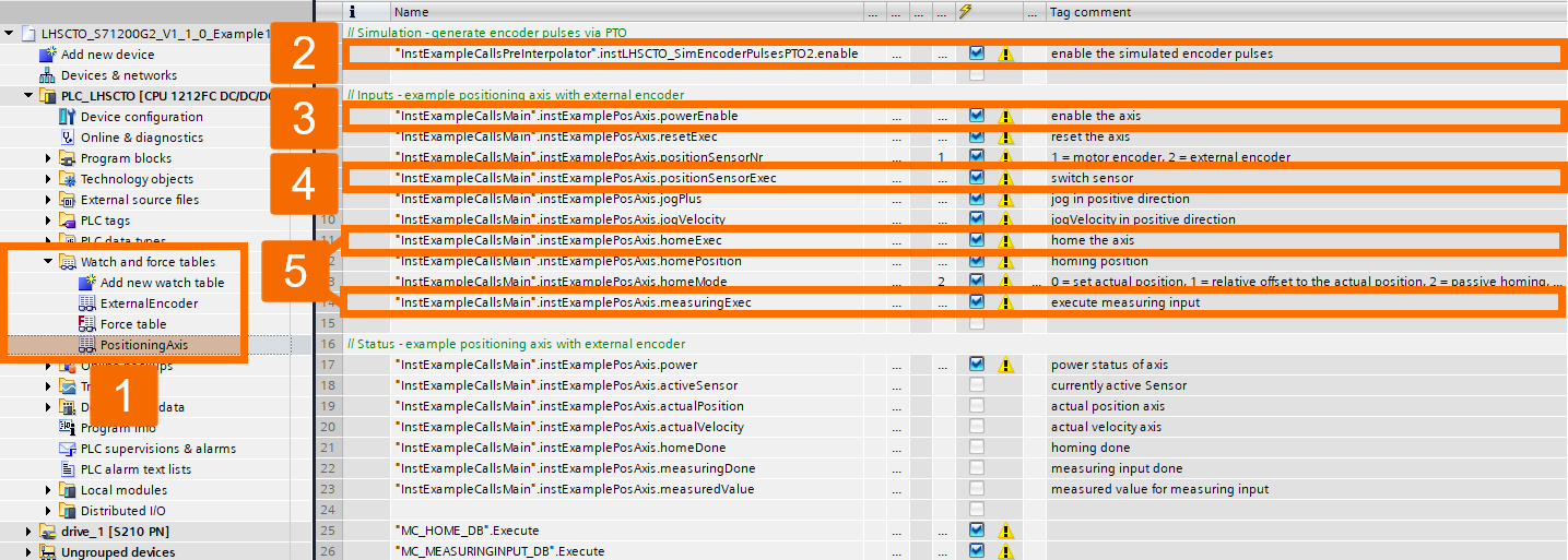
To try this application example using an additional encoder for the position feedback, follow these steps. Make sure the 'PositioningAxis' Technology Object is enabled. Change the sensor selection to the external encoder. Homing or measuring input should be requested when it's needed.
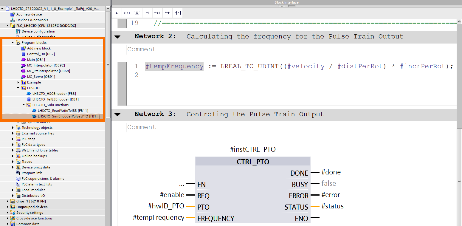
As an additional feature, the 'LHSCTO_SIMEncoderPulsesPTO' function block provides a simple example illustrating how an external encoder, through PTO (Pulse Train Output), can be simulated with A/B phase-shifted pulses.
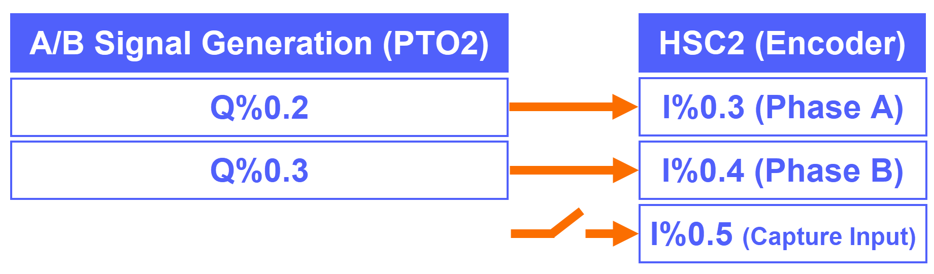
The S7-1200 G2's hardware configuration setup is a prerequisite for doing this step. Figure 5.4 shows how PTO1 is configured for this application example. PTO2's hardware configuration can be set up the same way. Here, the external encoder is simulated via A/B phase-shifted pulses.

For the configuration that pairs two Technology Objects called 'ExternalEncoder' and 'MeasuringInput' together, the wiring is shown in Figure 5.5.
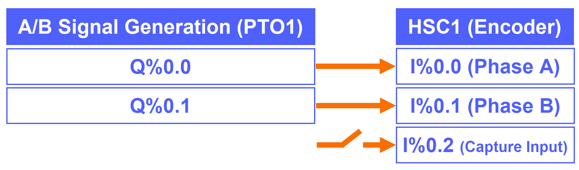
For the configuration involving the 'PositioningAxis' Technology Object, the wiring is shown in Figure 5.6.
If you want to test the application example using PTO1 simulation for the 'ExternalEncoder' Technology Object configuration, here's what to do. Configure the simulated velocity accordingly. Make sure the simulated encoder pulses are enabled. Carry out the operation the way Figure 5.1 explains.
If you want to test the application example using PTO2 simulation for the 'PositioningAxis' Technology Object configuration, here's what to do. Ensure the simulated encoder pulses are enabled. Carry out the operation the way Figure 5.2 explains.
Conclusion
In conclusion, you have learned how to bridge the S7-1200 G2's onboard HSC to Technology Objects using the LHSCTO library, wiring an encoder and measuring probe, configuring HSC1 and its capture input, and properly setting input filters to avoid missed signal edges. You've also configured ExternalEncoder and MeasuringInput Technology Objects through telegram 83, calculated fine resolution for a quadrature-counted encoder, and set up PositioningAxis homing via digital input or zero mark. Finally, you tested everything using the watch table and saw how PTO-based pulse simulation lets you verify the whole setup without any physical encoder on hand.


