Configuring a High Availability S7-1200 Modbus Cyclic Data Exchange

Introduction
Modbus is a widely used Industrial Communication Protocol. A handful of industrial equipment relies on this Protocol because of its practical data exchange structure and coverability of field scenarios. Even though setting up communication between devices with the protocol is not often a complex task, industrial communication needs to ensure data and communication channel availability.
When proposing a High Availability process, all process-related data (sensors, actuators, process logic states, diagnostic and monitoring information) require establishing a continuous communication interface. Therefore, a communication failure between two industrial devices might impact days of plant operation, depending on the process.
In this tutorial, you'll learn how to configure a High-Availability Modbus/TCP cyclic data exchange by developing an organized and structured sequential read/write with a recovery support algorithm to the usual Modbus Communication. This will help mitigate the impact of the loss of communication over controllers and field devices.
Prerequisites
What you will need to follow along with this tutorial are
- An installation of TIA Portal software on your computer. The TIA Portal version 16 will be utilized in this tutorial; however other TIA Portal versions are also acceptable.
- Overall understanding of TIA Portal Function Blocks and Data Types Programming.
- An understanding of SCL Language inside the TIA Portal.
- An understanding of Modbus TCP Configuration in TIA Portal.
- An understanding of State-Machines in Ladder Logic.
Project Structure
When talking about Modbus read/write functions, in TIA Portal, every instruction refers to a predefined data length. This tutorial will cover a structured multiple Modbus communication routine based on a High-Availability system. The main structure of the function is presented in Figure 1.
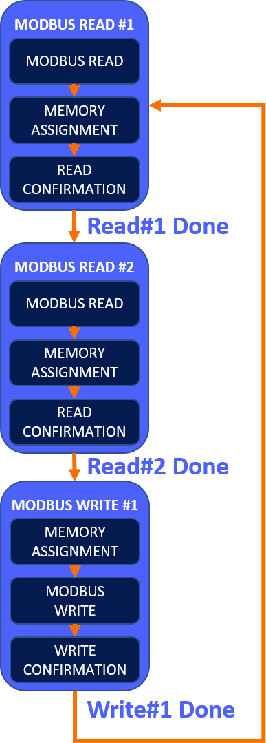
Our code will be structured based on the sequential read and write of Modbus registers in each state machine step. It’s essential to follow these tips for each operation:
- Read operation: Call the Modbus Client Function Block, assignment of the read information to the desired destination, and read confirmation to proceed to the next (read or write) step.
- Write operation: Assignment of the desired memories to write into the target registers, execution of the Modbus Client Function Block, and written confirmation to proceed to the next (read or write) step.
Ladder Development
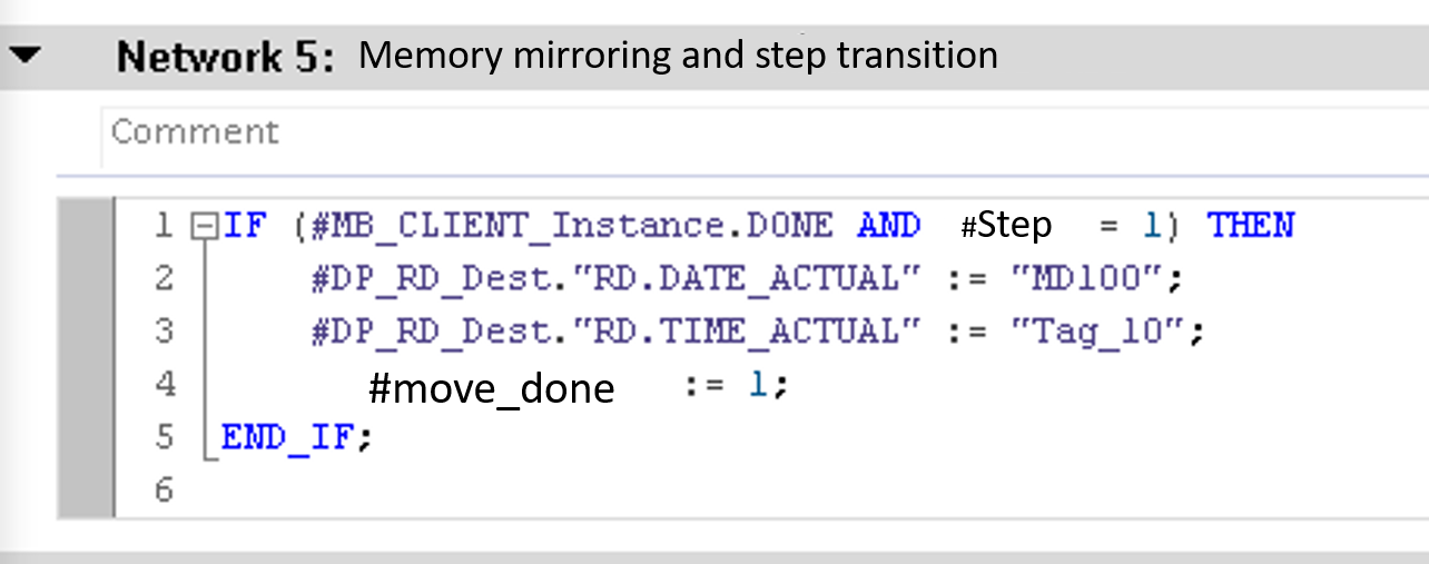
A Modbus read example on the first step of a State Machine can be found in Figures 2 and 3. We’re utilizing memory starting from offset M100.0 to store every read/write record. In this operation, holding registers starting at 10#01280(when in hexadecimal base, 16#500) are stored in 8 bytes (4 holding registers), starting from MB100 to MB107. Since we’re reading multiple holding registers in this step, the recommended MB_Mode is 103, the MB_Mode is to be configured according to each operation. For our Modbus Connection, we’re utilizing a dynamic connection which refers to an Input of the Data Type “TCON_IP_v4” for the Function Block Call.
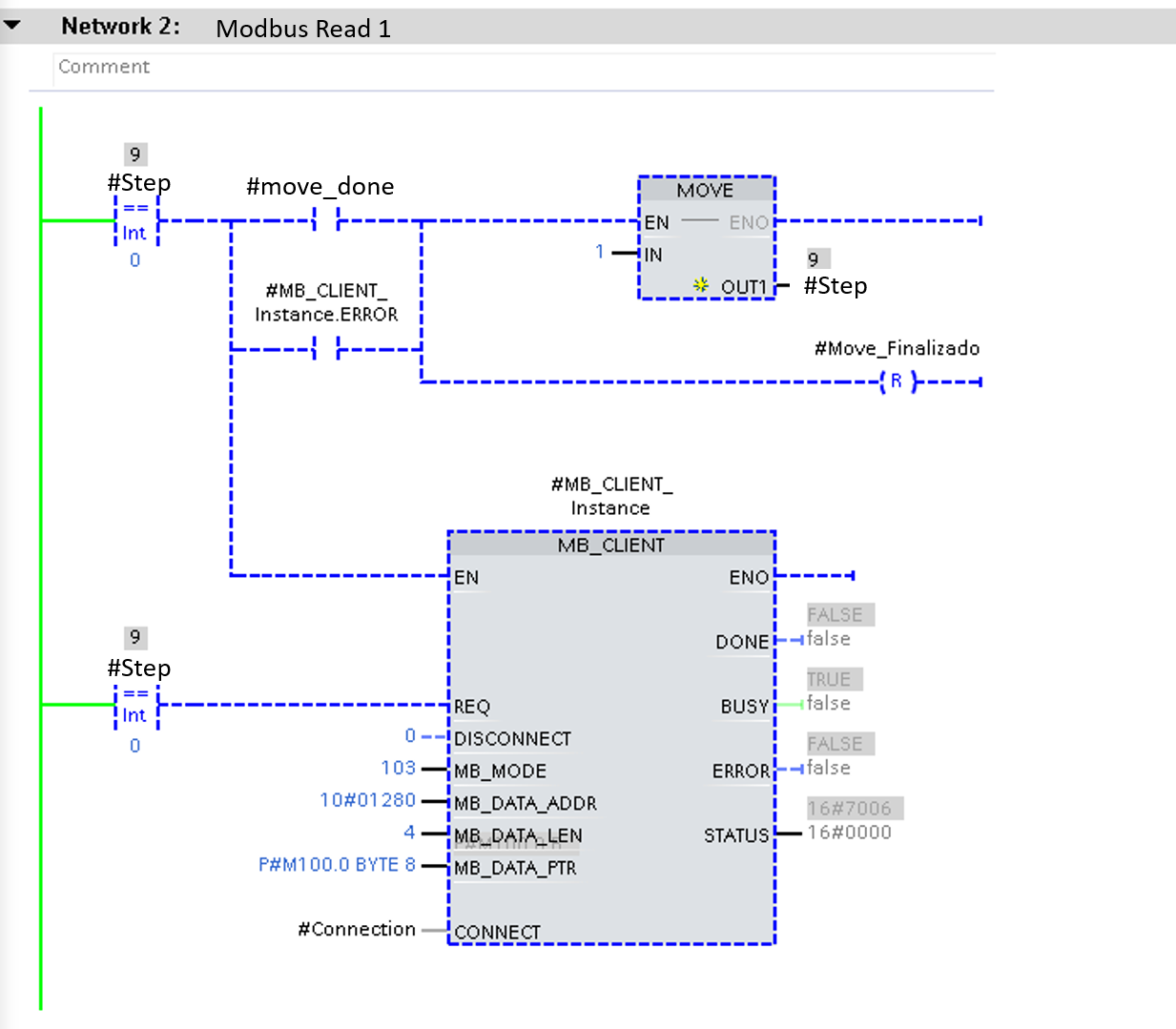
After storing the holding registers, we’ll assign the data to the desired memories inside our user program. In this example, 4 holdings registers were mapped to “DATE_ACTUAL” and “TIME_ACTUAL” Double Words. Please note that “MD100” and “Tag_10” correspond to memory areas %MD100 and %MD104. Observe that the transition to the next step in the state machine depends on the complete execution of the Modbus read function block after the memory is assigned to the destination memories. A signal of error from the Function Block is also a transition condition; this is done to make sure to cycle between the other read/write operations in case of a particular register’s access error.
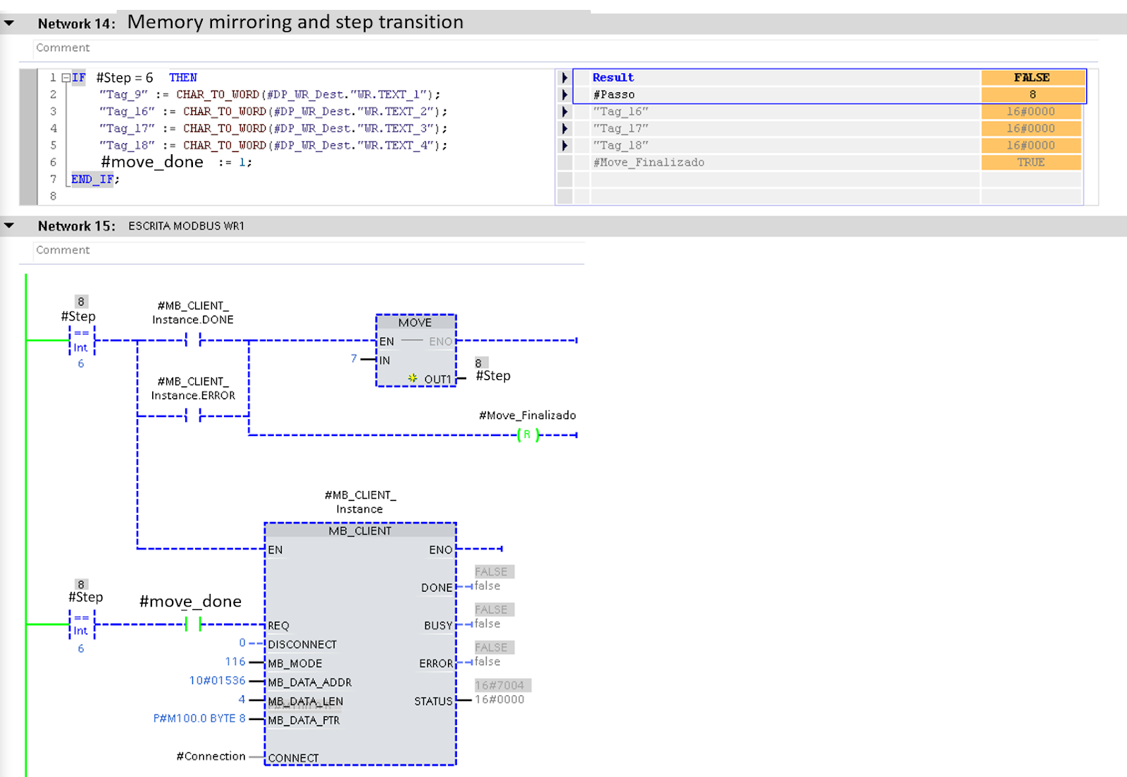
Modbus writing of multiple registers is covered in Figure 4. In this operation, we need to write 4 char variables to 4 different Holding Registers, starting at address 10#01536. Again, MB_Code 114 is utilized for multiple Write operations. Since a Char is equal to a single Byte’s length, converting each Char variable to a word is necessary. The logic structure is very similar to the reading operation, but in this case, note that the Memory Assignment is done before the execution of the Modbus Client Function Block. This is done to ensure that the correct data is attributed to the mirroring memory area, which is then mapped to write the target registers.
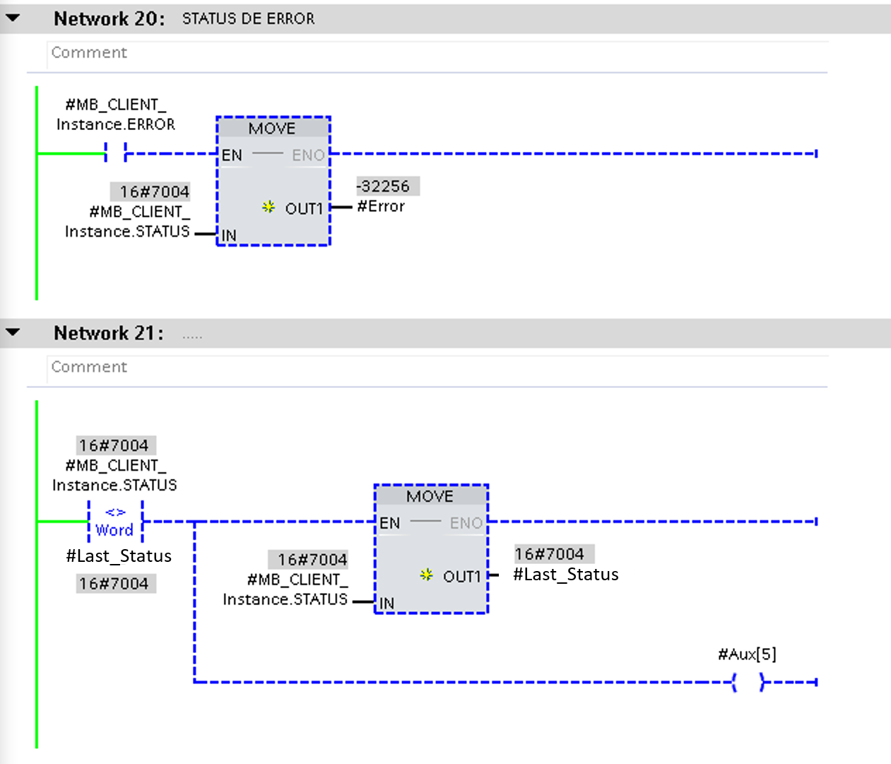
We’re cycling between multiple Modbus Client Function Blocks with the same Data Block instance, so Figure 5 brings an error detection and error code collection of each code execution. This means that if an error occurs in any of the steps, this error is detected, and its error code is stored in Static Memories (#Error and #Last_Status).
System Recover
When a Read or Write error is detected, we must test the connection interface for its integrity. Even though the Modbus Client Function Block is very well structured and covers communication recovery, its high recovery time might result in an undesirable loss of communication. Figure 6 presents a connection ID management routine to ensure instant communication recovery. We will force it to another connection ID if the current connection presents an error. This means the Siemens CPU will re-initialize all connection parameters referring to this Modbus function call and re-estabilish the communication. In this example, two different instances of the sequential Modbus Function were processed, having each of these two predefined connection’s IDs toggle in case of errors (ID 5 toggles with 8 and ID 9 toggles with 6 in case of individual errors).
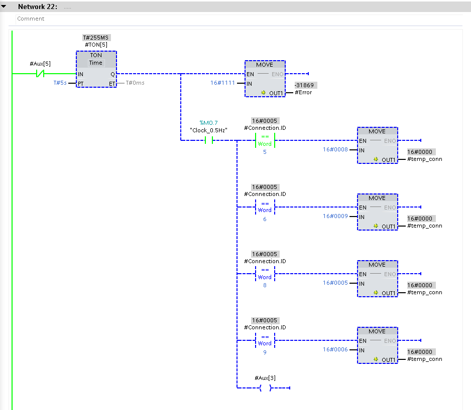
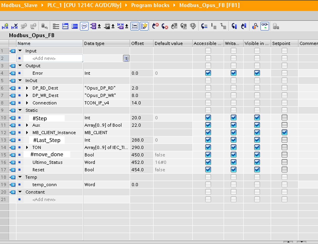
Figure 7 brings the complete variables’ structure for our Modbus Cyclic and High Availability communication Function Block. Besides the static variables, structs with the proper (and project-specific) data types were utilized as input and output data. Furthermore, to make the function block scalable, the siemens’ connections structure was also dynamized by an input.
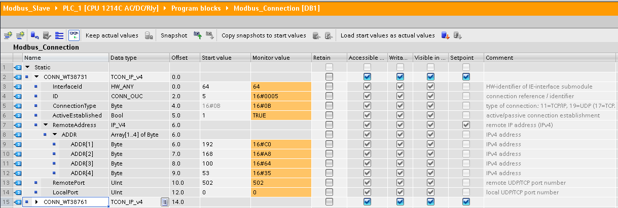
Each of the connections utilized in this function block was created in the following Modbus Connections DB, in Figure 8. Be aware that the Modbus Read/Write block utilizes the data type “TCON_IP_v4”. The destination device’s IP ADDRESS should be defined in the “RemoteAddress”.ADDR vector, where the first byte corresponds to the first IPv4 octet. Setting the correct RemotePort (destination device Port utilized for Modbus TCP Server) and LocalPort(local port in the Siemens PLC to cover the Modbus TCP Client) is also mandatory. When LocalPort is set to 0, Siemens PLC automatically defines a free port for communication.
Conclusion
Modbus TCP is a handy tool for communicating with various devices in the industrial automation scene. Siemens automation in TIA Portal provides an easily configurable Modbus communication block. However, because of the protocol’s architecture, developing a sequential read/write routine is often recommended.
SCL language is especially useful for data-types conversion and assignment handling, as well as multiple memory assignment operations. State-Machines’ structure also comes in handy when dealing with sequential algorithms, and these tools facilitate the development of organized and efficient programming routines.
