Configuring Produced and Consumed Tags in RSLogix/Studio 5000

Introduction
Moving data from one PLC to the other is a very important and necessary task for a modern control system.
As a Producer PLC, we can share that same data with many PLCs on a network. For the Consumers, this becomes an easy, predictable method to get the data as well.
By the time you complete this tutorial, you will have the skills necessary to move data using a Produced and Consumed model between two CompactLogix PLCs.
Prerequisites
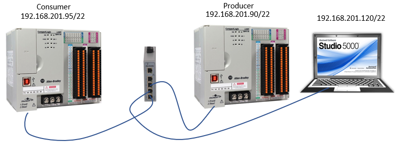
The hardware we will be using is two CompactLogix L24ER-QBFC1B controllers with V24 firmware.
This same method will work using any RSLogix 5000 or Studio 5000 based PLC with very little to no changes at all.
The software used will be Studio 5000 Version 24, but again, any version could be used with minimal changes.
The last piece that we need to this puzzle is a network switch so that all devices can be physically connected. Along with that is a logical network configured so that all devices are on the same subnet and can communicate together.
Adding the PLCs as Modules
We will start with the Producer PLC. In this controller, we will add a module to the Ethernet tree. This PLC will be consuming the tags that the current PLC Produces. Adding it as an Ethernet Module is a much more reliable way of communication with a PLC versus a message instruction. It is deterministic in nature and the data travels across the network in almost real-time. This makes it much more suitable for time-sensitive applications such as motion control and PID loops.
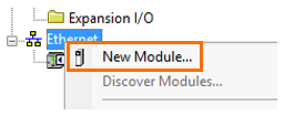
After we create a new project, we will right-click on the Ethernet card and select New Module.
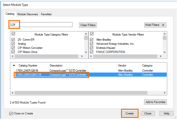
To select the module type, it is helpful to apply a filter. This will narrow down our choices. Simply type L24 at the top and this will limit our selections to only the L24 processors. All we must do then is select ours from the list and click create.
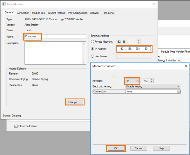
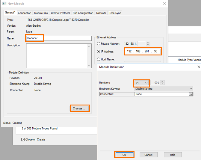
When we click on create, we will be shown the new module's general properties. Here we give the module the name of Consumer and set the IP address of that controller. We must also declare the correct module definition where we will select the correct firmware revision that is in our controller. In this case, it will be version 24.
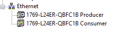
You will end up with two controllers in your IO configuration. The top one is the network interface of this controller, called Producer, and the bottom one which is the other PLC, now added to the IO structure of this controller, called Consumer.
Now the process is repeated in the other new project called Consumer. I will skip through the first few steps as they are identical to the above. Below are the new module’s general properties for the second project. Notice the only difference is the name and the IP address.
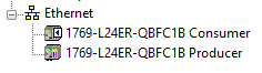
Here is the result of our work in the second program for our Consumer PLC.
Setting up the Produced tags
Going back to the Producer project we now need to create a controller tag that we will call Produced_Bits. Use the data type of DINT and most importantly the type of Produced. The Produced type will allow other PLCs to read this tag from the network connections.
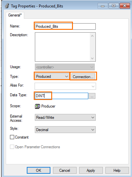
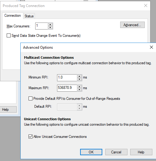
To make changes to how many consumers can connect to this tag at one time click on “Connection”. Here you will see some of the details about the connection including max Consumers and RPI settings under advanced. The defaults in this case will work best for us as we only have one PLC consuming our tag.
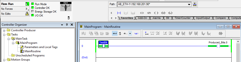
Now that we are done with making the produced bits, open the MainRoutine and create the following logic.
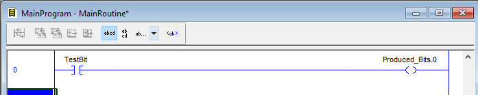
This will just give us a TestBit that we can use to toggle on one of our Produced_Bits when we get to testing. This program can now be downloaded to the Producer PLC.
Setting up the Consumer tags
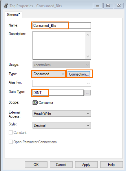
Now finally we will go back to the Consumer project and finish everything up. Again, we have to go to the Controller Tags and create a new tag that we will call Consumed_Bits. This will be of the same data type DINT but the type will now be Consumer.
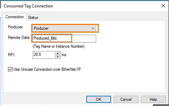
Next to the Type of Consumed, we will click on “Connection…” because here we will have to tell it where we are going to Consume that data from. Select the dropdown and pick our only selection. This is because it is our only module in this project capable of producing data. Last the Remote Data is the name of the tag in the producer PLC that we want to connect to.
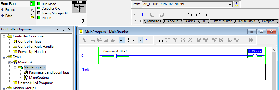
The final step before we download and test this project is to make a single rung of logic to see if everything works.
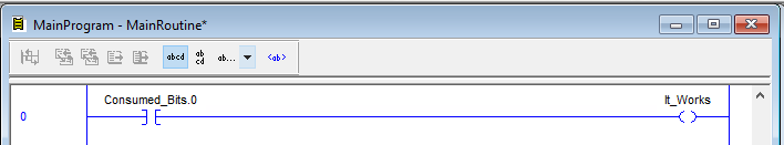
Now, download this program into the Consumer PLC. Then bring both programs into view so we can see if everything is working. Toggle on the TestBit in the Producer PLC and then see the It_Works bit come on in the Consumer PLC.
Conclusion
You have now successfully configured near real-time data transfer between the two CompactLogix PLCs. This very straightforward programming does have some weaknesses, such as if communications were to fail because of a network error or other cause, we would have no indication of that. Our data would simply freeze, and we would have no idea if the data was up to date from the other controller.
In the following tutorials, we will show you how to capture these error conditions. This method of using produced and consumed tags is considered a best practice for moving data between any of the Logix series controllers and is superior to the Messaging technique that was heavily used in the past.
