Connecting an S7 Siemens PLC to a Touch HMI and Configuring PLC Tags and Data Structures

Introduction
In an industrial environment, the smooth operation and ability to handle requests without problems is crucial to operation, so we must build robust code that allows for the unexpected and in doing so, the HMI becomes the central place that operators will go to to diagnose problems.
It’s important to be able to operate the system from the HMI without the need to interrogate the code to see what is happening. The PLC and HMI must work seamlessly together and operate without issues.
This is the first in a series of tutorials where we’re going to create a project to keep the score in a football (aka soccer) match. This will help you understand how to begin a project from scratch and accomplish all the aspects required; linking a Siemens S7-300 CPU 317-2 PN/DP PLC to a Siemens TP700 Series 7 inch Touch Screen HMI, writing the PLC code and designing and building the HMI project.
In this tutorial, you'll learn how to add a Siemens S7-300 PLC and a Siemens TP700 Series 7 inch Touch Screen HMI to a project, set up a Profinet and an HMI connection between them, and create PLC tags, utilizing both the built-in PLC Tags in TIA Portal and using Data Blocks to hold your data using structures.
If you’re new to Siemens PLC programming, and would like to follow along this tutorial, make sure to read our introductory tutorial to Siemens PLCs.
Configuring and Connecting a Siemens S7-300 PLC to a Siemens TP700 Series Touch Screen HMI
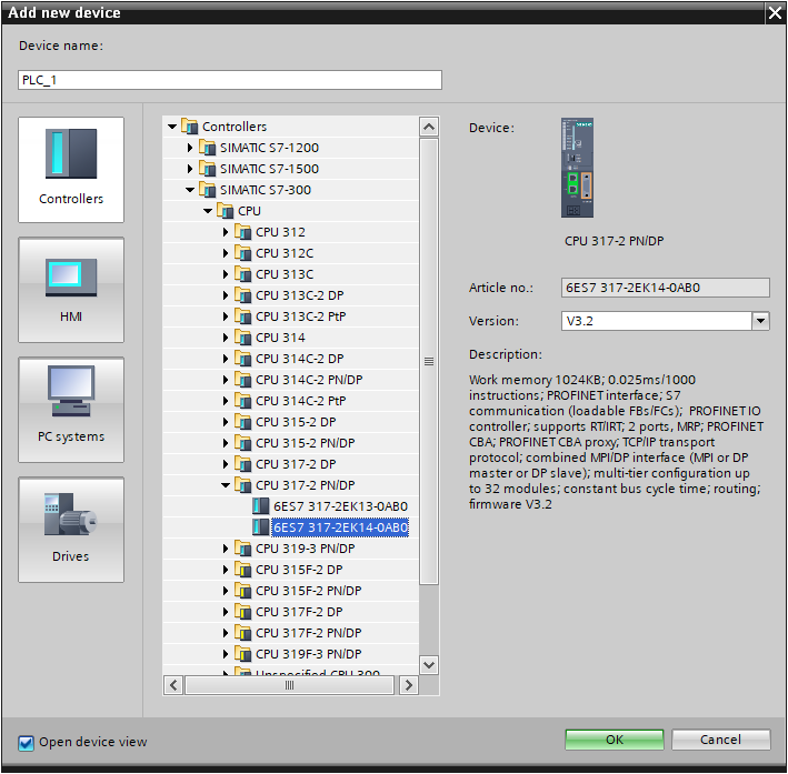
Let’s start by adding our devices. first let’s select the PLC;
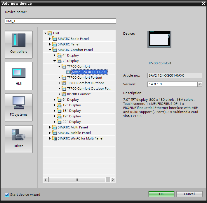
Now let’s add the HMI;
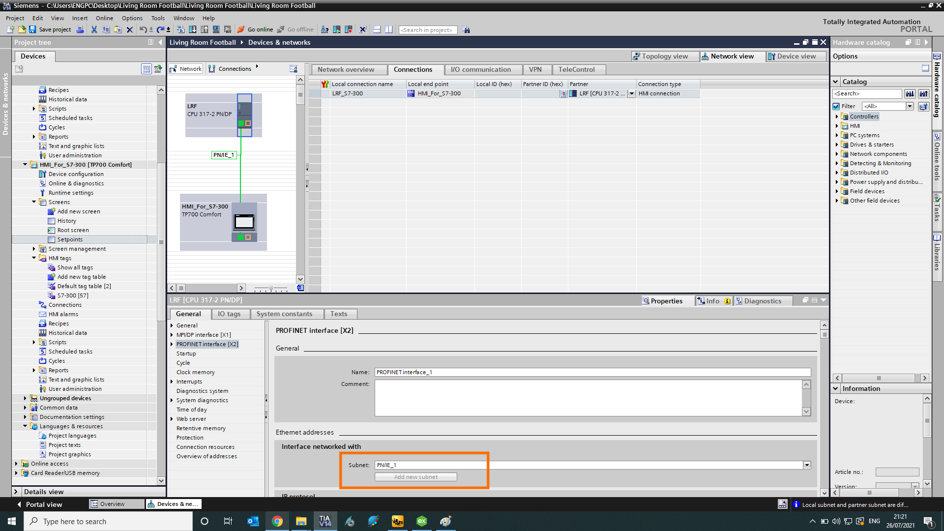
When they’re added to the project, we need to create a connection between them. To do this, we open up the “Devices & networks” window.
First we should add a new PNIE network. This lets the PLC and the HMI know that they are intended to be physically connected.
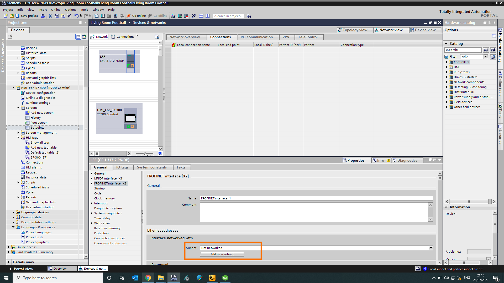
Do this for the PLC first, and when you come to the HMI, you can assign it to the network you just created for your PLC.
Now a connection is made between the two devices.
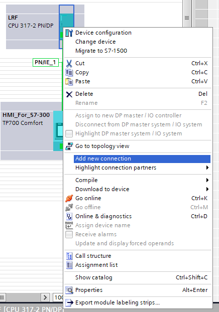
Now we need to make a new connection.
Click “connections”
Click “Add new connection”
Highlight the ‘PROFINET’ interface
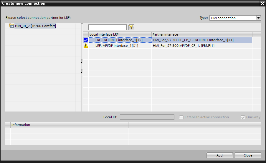
Create new connection
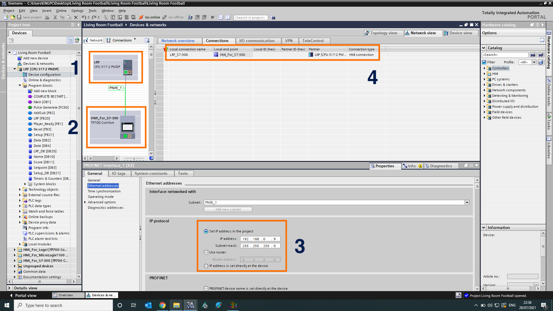
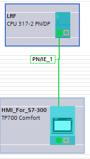
The screenshot above shows the PLC and HMI added to the project. 1 - PLC. This is connected to number 2, the HMI, by a green line. This green line represents an ethernet link, from the PLC to the HMI with number 3 showing the IP Address of the PLC. Finally, number 4 shows the connection is made between the two points, meaning its parameters and settings are valid. If there was an issue with the configuration, there would be in red, for example

If you were to see something like this, you know that there is something that needs correcting.
Under “Connections” in the HMI which has appeared in the project tree, you can verify this connection, which will enable us to search for and add tags to our HMI project.
Et voila! The configuration is complete.
Now that we have completed the configuration of our PLC and HMI, it is time to start programming them.
Setting up PLC Tags and Initial Data Structures
Understanding Organizational Blocks
We will start by setting up the data structures. With Siemens PLCs, this is done using Data Blocks.
We have Organizational Blocks (OBs) that interface between the user programmed functions and the operating system. An example of this is to use the OB100 function, “COMPLETE RESTART”. This organizational block runs once on PLC startup or change of state of the mode switch and will not be called again.
This type of block is useful for programming a “FirstScan” flag to trigger the setting up of parameters or to delay a communication protocol from scanning immediately after powering up the PLC.

Understanding Function Blocks
Function Blocks (FBs) and Function Calls (FCs) are similar in so far as they are both used to write functions which can be reused throughout the program, but where they differ is that Function Blocks have a memory which means we can address the tags of a Function Block outside of said block. With Function Calls, you cannot do this as the memory is temporary.
The Function Blocks store their memory in Instance Data Blocks. If an FB, FB1, has an Instance Data Block DB1, then the memory tags from FB1 can be addressed as “DB1.xxx”.
Understanding Data Blocks
Data Blocks, as the name suggests, are where we can store our data which can be used throughout our program. We can read from and write to these blocks, so we can keep track of our score in our game!
When writing PLC programs, it is useful to have a tag that is always a logic 1. This means that when we use it, the output is always on, so it is useful for conditional rungs. The same can be said of a logic 0. This output is always off. This can really be put anywhere, but I tend to place it in a “Housekeeping” block, or in this case a “Setup” block. This is where I will set up my initial data. We could use the “Initial Values” in the data block to set up values, but this is mostly used for when the PLC is fully downloaded. When we do that, it overwrites all of the current values with the initial values, so anything we haven’t correctly documented, or any live changes aren’t captured. Doing it in the FB in this way means that doesn’t happen.
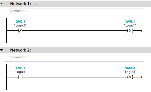
Always On / Always Off
Here we have the Logic1 and Logic0 tags. When the PLC starts up, both the Logic1 and Logic0 will actually be ‘0’. What we are doing here is checking whether the Logic1 tag is ‘0’, and then setting it to ‘1’. Then once we have Logic1 at ‘1’, we set Logic0 to ‘0’. This way we can be confident that we can use these tags and the outcome will be as expected.
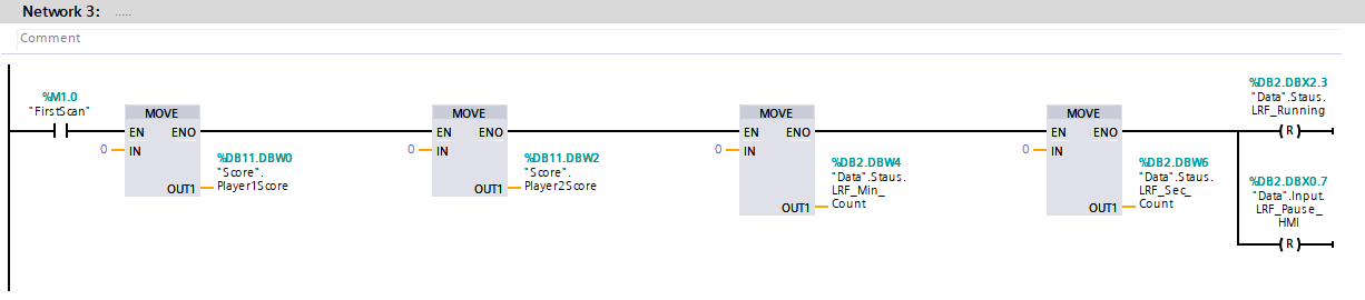
We want to make sure that the player’s score and timers are at zero when we start up. This way we can start playing sooner! We also make sure that the running flag and HMI button press is off in case it was on the last time the PLC was running.
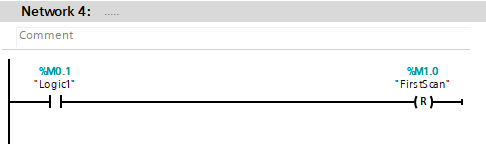
Since we’ve now parameterised the PLC with our preferred start values, we can now reset the “FirstScan” tag we created earlier:
Configuring Clock Memory
To make our project work correctly, we need to be able to accurately count the time to a desired number of seconds or minutes (or hours!), so a function we use to do this utilises the PLC clock pulse. You can set this up by going to your PLC “Device Configuration”, and on the General Tab, select “Clock memory”. Tick the box to enable the Clock memory, and assign it a memory byte. This byte will give us a clock pulse
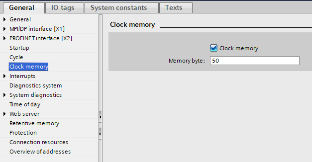
Configuring the PLC Clock Memory
You can use clock memory, for example, to activate flashing indicator lamps or to initiate periodically recurring operations such as recording of actual values.
Available frequencies
Each bit of the clock bit memory byte is assigned a frequency. The following table shows the assignment:
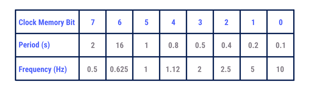
Since we want a 1 second timer for our clock, we need to look at memory bit 5 of memory byte 50. We can use a pulsed signal to increment a counter to work as my clock. This way we can easily pause the game for a quick hydration before carrying on for the second half.
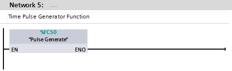
To get a pulsed signal, we can use the memory bit 5 of memory byte 50 and use another two bytes to make a pulsed signal. This section of code uses STL, not LAD like the rest of the code, but it could just as easily be done in LAD. The reason we chose to do it this way is so that we can map all the memory bits to pulse flags without rungs and rungs of code.

As you can see, bit 5 of byte 50 is Clock1Hz. The FP instruction looks for a change of state from 0 to 1. Once it see that, it turns on “Pulse1sec”. Because the FP instruction is only on for 1 scan, the bit M51.5 is also only on for 1 scan, so we can use it to pulse a counter instruction.
Now when we call this Function Call in our Setup Function Block, we’ll have accurate timing for our game.
Configuring PLC Tags
Our PLC tags look like this;
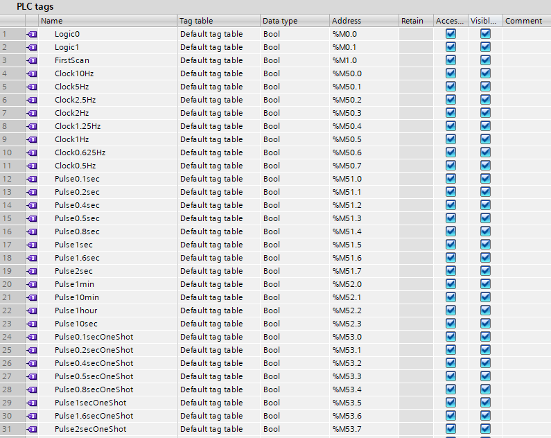
These are the tags we’ve assigned to our Logic0 and Logic1 tags, FirstScan tag and our clock memory bits with pulses.
The next task is to set up our Data Blocks with the data we will need for our project.
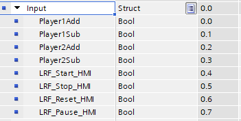
We need to create quite a few tags here, and there is no better place to start than with our “Inputs”. We need a way of adding and subtracting scores (depending on VAR), and also a Start, Stop, Reset and Pause.
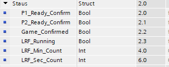
Next we need to consider “Status” bits. Here we can program in a confirmed start using a positive input from the PlayerXAdd “Input” from above. When both players have confirmed, we have a Game_Confirmed” status. We also have a Running status, and the accumulated counter values for the minutes and seconds values to display on the HMI.
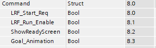
“Command” bits come next. Here we define our command requests such as to start the game, or to show a ready screen where the players confirm their intention to play. We’ve also got an animation that can be shown when a goal is scored.
Finally we have some One Shots that can be used in the program, for example when the game ends, we copy the result to a history table.
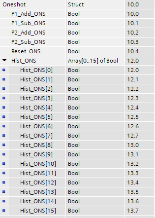
This moves the current score to the first history placeholder, the theory being that once the game stops, the following happens;
.png)
We need a “Name” and “Score” Data Block to keep a track of the names of the players, and their scores.
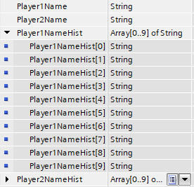
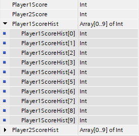
The PlayerXNameHist[x] and PlayerXScoreHist[x] data contains the data in the history log. These registers are held as an array of ‘String’ for the name and an array of ‘Int’ for the score. You can set the number of elements in the array by using ‘Array[lo..hi] of type’. When we address a particular entry, we use its array number to identify it.
The final piece of data we need for this project is a Setpoint Data Block. The only Setpoint we have to include here is the duration of the game to be played. This is because we’ve already got a “Name” Data Block which captures the names to be used, and it makes sense to keep them with the historical entries. The game duration is an integer which when entered will provide us with the number of minutes for the game to be played.

Now we have everything set up, the next step is to write the code to control the game, and to create and tag the HMI screens.
Conclusion
Let us now recap what we have learnt in this tutorial. We’ve added a PLC and HMI to a project, set up a Profinet and a HMI connection between them. This will allow them to communicate and transfer data between them. We’ve created some PLC tags, utilising both the built in PLC Tags in TIA Portal and using Data Blocks to hold our data using structures. By using structures in the Data Blocks, we can separate out signals into different sections, like “Inputs” and “Commands”. They are in the same location, but the prefix we use in the code will make them easily identifiable.
We’ve also created a First Scan, Logic1 and Logic0 flags. The First Scan flag can be used within our code to trigger something on PLC startup such as setting default values, or resetting counter values. The Logic1 and Logic0 flags are useful for disabling code whilst being tested, or when we want to use a branch and qualify the run with a positive signal.
Setting up the clock memory of the PLC has given us the facility to have accurate timing, something that in our test project is extremely useful to keep track of the time.
In the next tutorials, we’ll be getting down to writing the PLC code to control the game, utilising the tags we’ve created, and designing the layout of the HMI screens and tagging them up.
