Siemens PLC Function Block Programming and OPC Server Configuration

Introduction
The critical part of PLC programming in industry is being able to write and debug robust code. This means that we must always be thinking of ways to make the code fail in order to fix it so it cannot happen again. This allows us to build robust code that will stand up to scrutiny and not fail, reducing the downtime of machinery.
In this tutorial, we will be continuing from the previous one where we configured a PLC and HMI project by setting up and connecting a Siemens S7-300 CPU 317-2 PN/DP PLC to a Siemens TP700 Series 7 inch Touch Screen HMI. If you haven’t seen this one already, be sure to read it so you are able to follow along in this tutorial where we will begin to write our program and create our HMI screens.
Following on from the last tutorial, we’ll be covering programming specific blocks that we can reuse throughout our code and creating an OPC Server to capture all of our inputs, before linking it all together and downloading both applications to our PLC and HMI in our final tutorial.
Writing the Function Block PLC Code
When considering where to start writing our PLC code to control our scoreboard, we need to think about what functions we are likely to need. One of the most important things for us is to be able to add to the score when there is a goal (and to subtract a goal when VAR rules it out!). So we’re going to start by programming a block that will enable us to add to and subtract from the score.
A fairly simple one to start; we set up our block with our inputs. We want to include an enable so that we can only amend the score whilst the game is running and an Add and Subtract input are a must. These form all of our defined inputs. The score is added to the block as an InOut. An ‘InOut’ variable in a function block header is for a variable that can be written to as well as read within the function, but can also be written to, as well as read outside of the function. Finally, we have Add_ONS and Sub_ONS. ONS here just denotes that it is a One Shot type signal.

Now that we have made the Function Block inputs and outputs, we can put them to work in a rung of code.
By adding Normally Open contacts (NO) in series, all of the conditions need to be true for the entire rung to be true. In our code we want the Enable signal to be one as well as the Add command input, so it looks like this below;
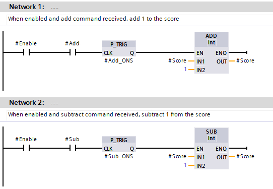
After the Enable and Add inputs, we have a P_TRIG function. This function waits for the preceding inputs to be true, and whilst it waits, its output is “0”. Then, when a positive signal edge is seen at the input CLK, the instruction executes. When this happens, the output of the instruction Q returns the signal state "1" for the length of one program cycle. If we didn’t have this instruction, each time we added or subtracted to or from the score, the add or subtract wold execute several times because of how quickly the PLC performs a single scan of the PLC, so by using a P_TRIG function we can make sure that the increment or decrement is 1 every time.
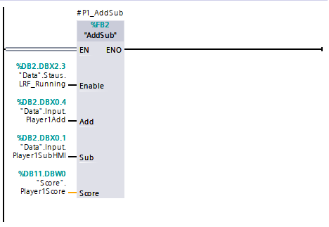
When we call our new Function Block within our code, we can assign it some of the tags we created in our lasst tutorial. We assign the “Running” signal to the enable as we’ve already identified. Then the Add and Subtract HMI buttons and the Score are added to complete the block assignment. As this a Function Block, it can be used again for Player 2, by simply tagging it accordingly.
Next up we’re going to program in a ready function. What this will do is enable the players to confirm that they are ready to start the game. To do this we need an external button for each player. In addition to the ready function, the button can be used to increment the score too. In this particular setup, the buttons we need to use are connected to a different PLC, as we do not have a Digital Input card on our S7 CPU. To access the status of the button and be able to use it in our project, we can configure an OPC Server to gain access to it. Open Platform Communications, or OPC, is a series of standards and specifications for industrial telecommunication.
By configuring a link between the two different PLC’s in this way, when the Input is actuated in one PLC, let’s call this one PLC 2, it, in turn, is actuated in our S7 PLC, PLC 1.
Creating an OPC Server
The first thing to do here is to create a new Data Block to receive our new signals. Keeping them separate means that we keep them with a logical structure and it can be easily identified. The “Comms” DB1 has only 2 tags, ‘Player1Button’ and ‘Player2Button’. Configured as Bool tags, they are either ‘True’ or ‘False’. ‘True’ when the button is pressed, ‘ False’ when the button is not pressed.

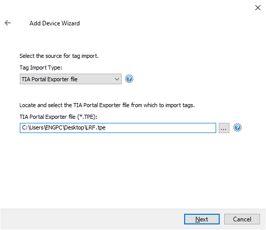
We can use TIA Portal Exporter to export all of our tags within our project to import into our OPC server, taking the pain out of manually adding them.
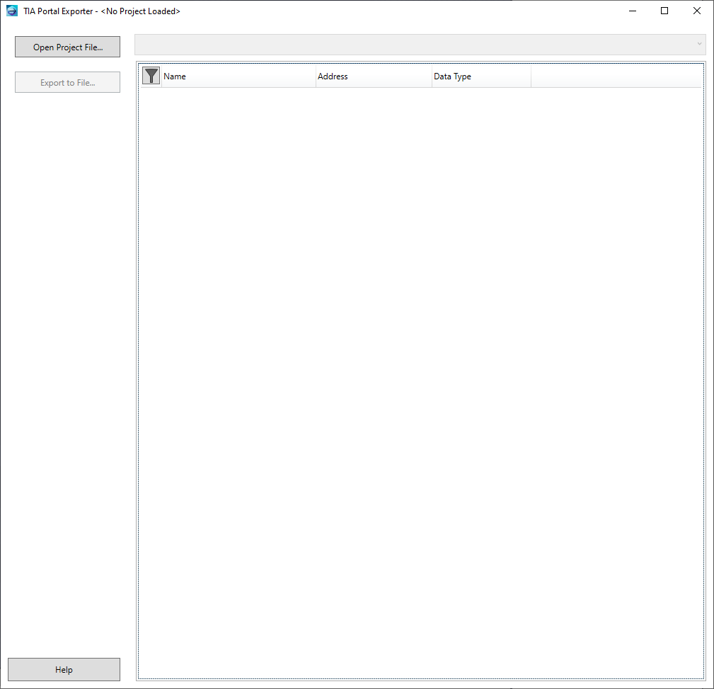
Open up the TIA Portal project file, and it loads the entire project. We can then select which tags to export, some or all of them.

Export them to a file, and the tag file is ready to import.
Now let’s go through the order of setting up the OPC Server. For this, we will be using Kepware software called KepwareServerEx.
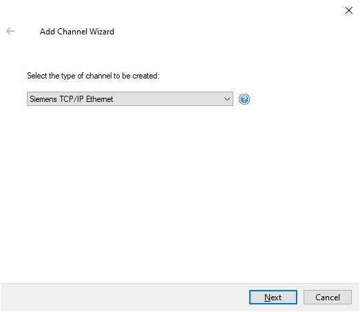
Firstly we need to select a new Channel. We can choose a Siemens TCP/IP Ethernet type.
Then give it a name

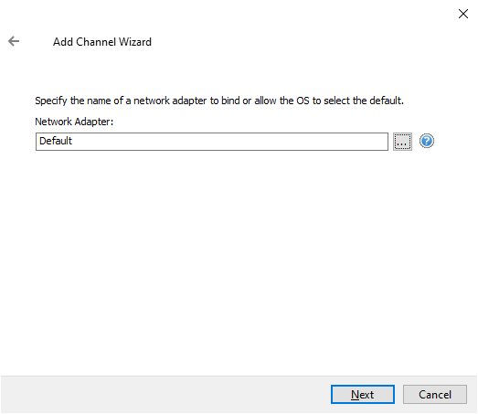
Choose a network adapter, or leave it as Default.
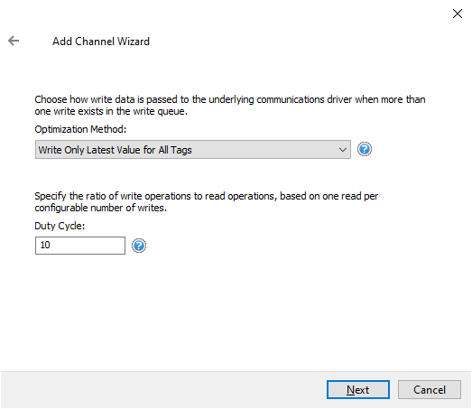
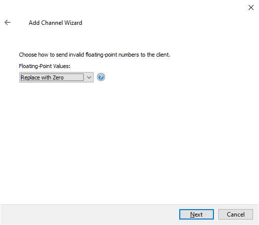
The next few dialog boxes don’t require any modifications, the default values are sufficient.
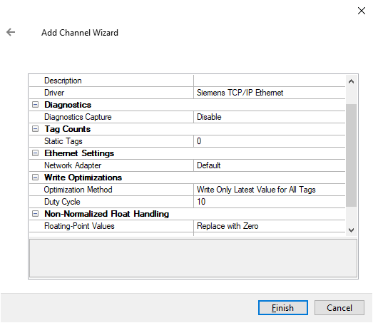
Click Finish to continue.
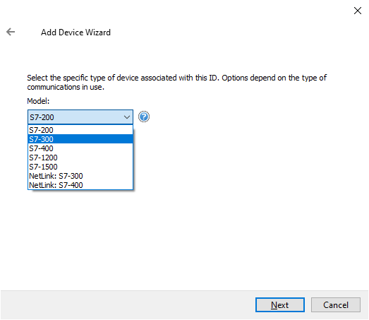
Now we’ve added a Siemens TCP/IP channel, we need to add our Device, in this case, the CPU.

We have an S7-300 series CPU, so select that.
Enter the IP address of the CPU. This is found in the Device Configuration in TIA Portal.

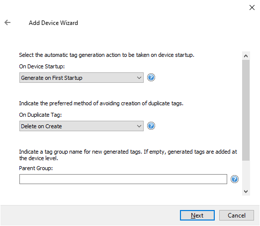
The next few dialog boxes can be left on their default values. The only one we need to concern ourselves with is where we let the OPC server know whether to create tags on startup or not. This is where we can add the tag file we generated from TIA Exporter above. The first dialog will select the tags to generate on the first startup of the OPC Server. This will populate the Server with the tags we need.
The second dialog box will allow us to add the TIA Exporter tag file in which the OPC Server will generate from.
Generating the Tags on the first startup of the OPC is a good option. It won’t constantly update, but it will be a good place to start.
Confirm with the Finish button to continue.
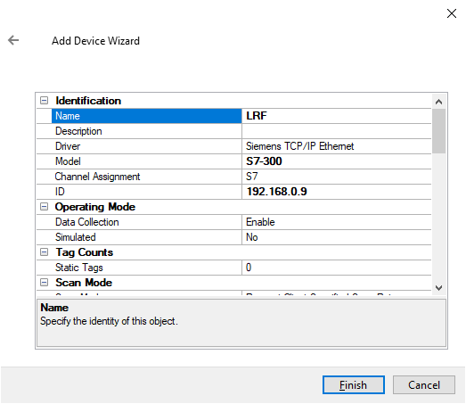
Upon clicking the finish button, the tags will be automatically created for us.

This is repeated for the other PLC within which the signals we need are stored, matching the PLC type up in the same fashion. Once that is complete, and we have all of our necessary tags within the OPC Server we need to create a link between them so that when the button is pressed, actuating an input in PLC 2, we receive the signal in PLC 1, our main PLC.
Creating a Link Master Connection to Transmit Signals
To make a link between different PLCs, using an OPC server, we can use a program called Link Master. Once our OPC Servers are created, Link Master is able to see and connect to them both.
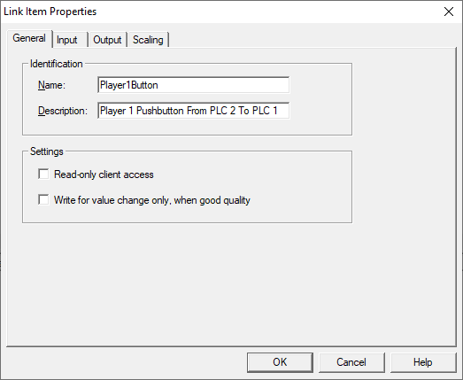
Start by creating a new Link Group. This group will capture our buttons to transfer the status between PLCs.
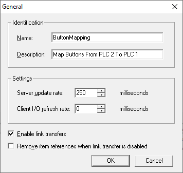
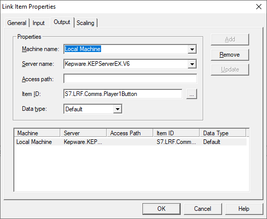
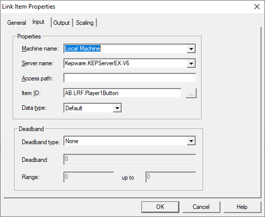
Then configure the signal link by selecting the two OPC Servers. Our PLC 2, the second PLC provides the Input, whilst our S7-300 PLC will provide the Output.
Repeat this process for the second button, and that is our configuration complete!
To check the connection is good, we can check the “Quality”. If it says “Bad” and all the signals are online, then there is something wrong with the configuration. If it is “Good”, then the connection is happy and is now ready for us to use.

Now we can use this signal in our code in parallel with the HMI button we configured to increase the score.
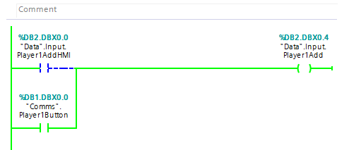
Adding it in parallel means that if either condition is true, the output will be set. The output is then mapped to the AddSub Function Block we created earlier.
Back to our Ready Function.
Creating a Ready Function
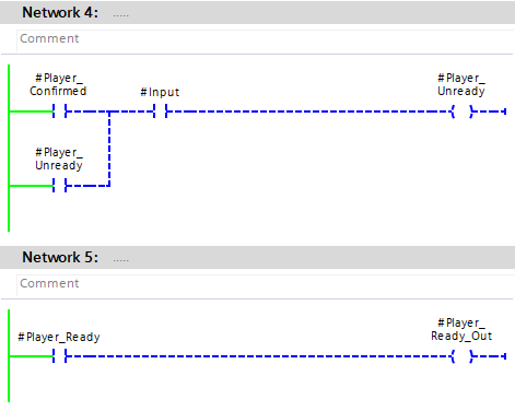
Now we have our signal and our wireless button is connected and working, we can program a block to perform a ready function. The purpose of this is so that each player can make sure they are ready and have the ability to control it so there are no false starts. In addition to this, if the player status is ready, and the player changes their mind, they are also able to “Un-ready” themselves.
Inputs for this one is an “Enable”, an Input (our button), and a “Time”. The time is the duration the button needs to be held for the player to be classed as Ready. If the button is held for less than this time, then they won’t be deemed ready. Our Output is the status of whether they are ready or not, “Player_Ready_Out”.
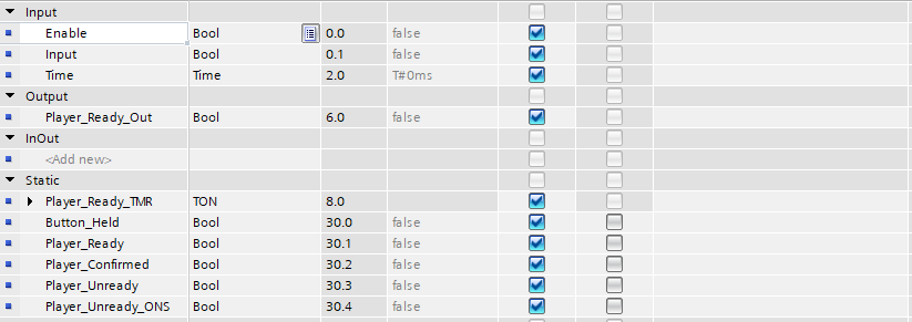
Our Static tags are here for the basis of our code. The “Player_Ready_TMR” is the timer, once expired, the “Button_Held” tag is made. This in turn turns on the “Player_Ready” tag. Once our push-button input is removed, the “Player_Confirmed” tag is made. This is latched in until the game is started, or until the input pushbutton is pressed again, which restarts the process.

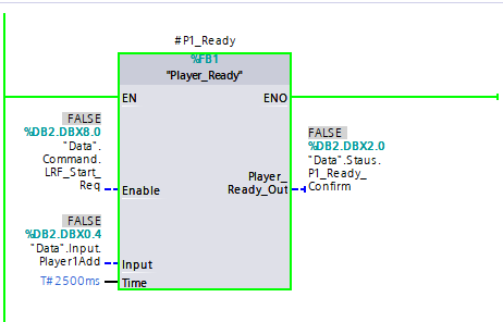
Once again, this is repeated for Player two, and we’re ready to move on.
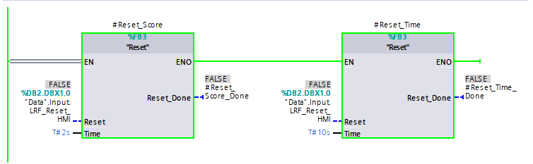
The final Function Block we need to create is a short one. It’s to be able to reset the scores or the time. To stop any erroneous resets, we can debounce the HMI button.
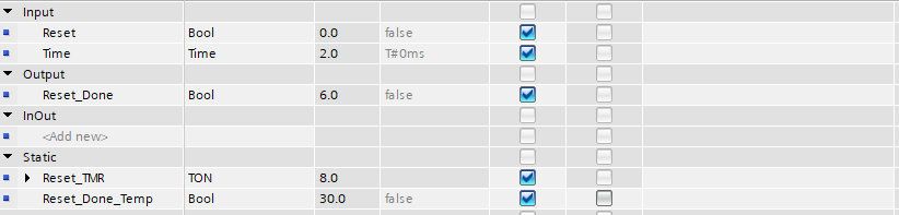
Assigning the Reset Function Block Interface tags
The input “Reset” is the reset HMI push button, the time input is the amount of time the HMI button needs to be pressed for. Our Output “Reset_Done” is what we can use in our code to confirm the operation is complete. The static tags “Reset_TMR” is the timer, and the “Reset_Done_Temp” maps the timer output to the actual output of our block.
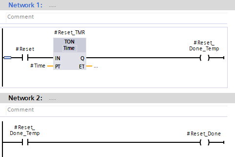
Construction the PLC code for the Reset Function Block
Conclusion
In this tutorial, we created code to control our PLC using the data structures we created during the first tutorial. We made an FB called “AddSub” to enable us to increase and decrease the score from an HMI that we’re yet to configure. We also created a Ready Function and a Reset function to add all the functionality we need to control our project.
One of the more complex things we achieved in this session was creating an OPC Server and a Link Master connection to connect 2 PLCs so that we could use some I/O from one PLC in another.
The second PLC, PLC 2 had two wireless buttons configured for it, so by mapping them across into our S7-300 PLC, we are able to use the wireless buttons to control our scoring system.
OPC Servers are used throughout different industrial environments all over the world. OPC is a widely accepted industrial communication standard that enables the exchange of data between multi-vendor devices and control applications without any proprietary restrictions.
An OPC server can communicate data continuously among PLCs on the shop floor, RTUs in the field, HMI stations, and software applications on desktop PCs. Even when the hardware and software are from different vendors, OPC compliance makes continuous real-time communication possible. OPC is extremely versatile and has certainly come in handy in our project!
In the final tutorial, we’ll be creating the HMI screens, tagging them, downloading them to each device, and testing our application.
