Designing HMI Screens and Going Online with a Siemens TP700 Series HMI

Introduction
Being able to write code to control plant equipment and implement fail-safe code is great, but not everyone can read and understand the code that we write. That is why you find HMI screens, some small and local to machines, and some large SCADA applications that monitor the whole plant. They are a crucial part of any working system that helps operators, maintenance personnel and managers alike a feel for how well their plant is performing, and areas that require attention.
This tutorial is the final one of three to demonstrate a small lifecycle project from concept to implementation. If you’ve made it here, well done, and by the end, you will have a fully functioning PLC, OPC Server, and HMI for our digital scoreboard!
In the first tutorial, we configured a PLC and HMI project by setting up and connecting a Siemens S7-300 CPU 317-2 PN/DP PLC to a Siemens TP700 Series 7 inch Touch Screen HMI. In the second one, we set up an OPC Server between two PLCs to receive the status of buttons connected to the second PLC.
Be sure to read these if you haven’t so you can follow along in this final part where we will be designing the HMI screens, before linking together all we’ve learned across the tutorials and downloading both applications to our PLC and HMI.
Overview of an HMI Object
Creating and Tagging HMI screens
We’ve previously completed the more challenging aspects of our project; writing the PLC code and creating OPC links to use wireless pushbuttons from another PLC. We now arrive at the artistic side of the project which is to create the HMI screens for our football scoreboard project. We need 3 key screens; one which displays the score, one that we can enter our set points, and one which will display our previous results. This type of screen structure is akin to what you will find in most industrial applications. There will undoubtedly be many more screens when covering an entire production line, but the similarities in how the screens are displayed in a structured way will keep things feeling familiar.
First up, we’re going to design our HMI Template. Using a Template means that the objects we place will be displayed on all the screens selected to use the Template.

If we view the properties of a screen, we can select whether it uses a Template or not, we could even have different Templates for different areas. For our project, we will be using “Template_1” for all of the screens.
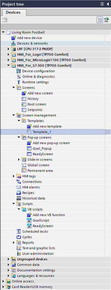
We are going to divide our screen up into three segments; the top banner, the bottom banner, and the central area.
The top banner will display the current screen title name along with the date and time. The bottom banner will display our navigation buttons. These buttons will be present on each screen we create. This will keep the look and feel of it consistent and therefore make it easier to use. As you can see in the image below, on the Template screen the buttons on the bottom banner appear in focus. This is because we define them on the Template, then on other screens which use the Template as a base object, they appear greyed out. This is because we cannot change the banner from additional screens, we do all the configuration on the Template. On the Template, we will leave the central area clear because we want anything in this area to be unique on our other screens.

The centre part of the screen will be specific to that particular screen, for example, the setpoints page will only include the setpoints, other pages will not display these.
The History screen is where we store the past results of the games. From tutorial 1, we can store up to 10 results. It could be that we could make additional pages or shrink the text down to fit more on this screen.
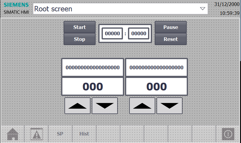
The Root screen is the one that starts up on the HMI when it is powered on. This is defined in the Runtime Settings under ‘Start screen’. We can also find the screen dimensions under the ‘Screen Resolution’. This is useful for adding pop-up screens as we’ll find out later.

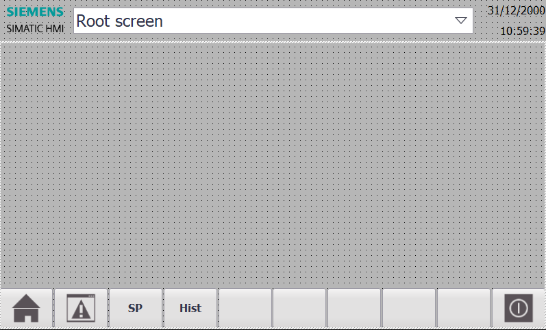
Now we will design the layout of the Root screen. We want to display the players’ names and their scores, whilst having our buttons to control the functions we’ve programmed. The up arrows will increase the score, the down arrows, decrease it. The Start, Stop, Pause and Reset will perform their actions and the elapsed time is displayed centrally.
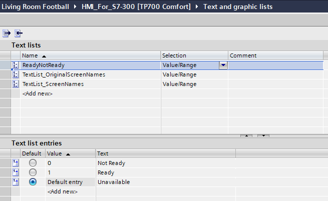
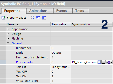
With the three key screens designed, we can look now at making some pop-up screens. We use pop-up screens when we want to display something without navigating away from the current screen. In our case, we want to display the Ready Screen when we’ve pressed the Start button on the Root screen. This pop-up will cover the items displayed and remain there until either both players have committed to starting the game, or the game is abandoned. To abandon the match, we need a Cancel button. We will also display whether each Player is “Ready” or “Not Ready”. This is derived from the “Px_Ready_Confirm” signal from the PLC. We can use this single Boolean input to drive a Text List. If the value is ‘0’, the Player is Not Ready. If the value is ‘1’, then the Player is Ready.
Adding HMI Tags and Tagging Screen Objects
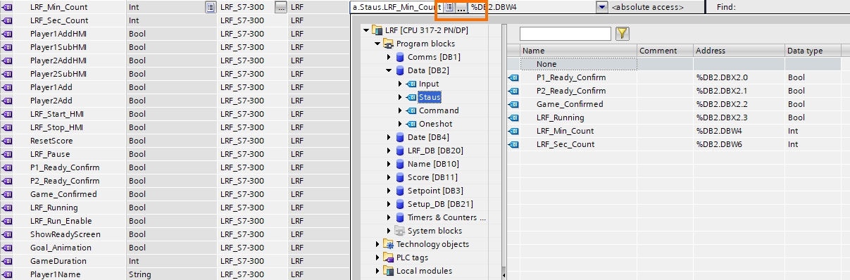
So we have designed our screens, but we don’t have any HMI tags yet. Since we already made our PLC to HMI connection in the first tutorial of this series, we just need to add in the tags we want and link the HMI tags to the PLC tags. Press is the dots icon [...] next to the tag you want to connect, and it will let you navigate the PLC tags.
When we’re finished, we have all of our tags connected to their PLC equivalent.
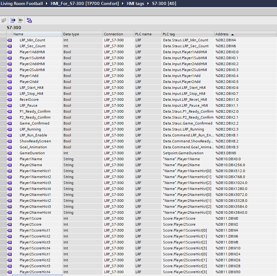
Now we have all of our tags, we can merrily go about tagging up our objects.
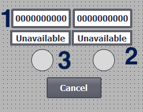
As you can see from the above, this is how we will tag the Ready Screen pop-up.
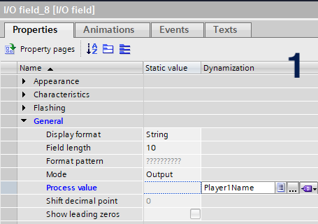
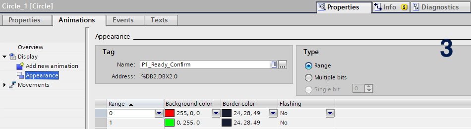
The first item, labelled ‘1’ is simply just the current Players’ name. ‘2’ is their current status; “Ready” or “Not Ready”. This uses the text and graphic list defined previously. Finally, we have an indicator ‘3’ that is also linked to the players current status, but this time showing a green circle when “Ready” and a red circle when “Not Ready”.
We size this screen so that it will fit between the top banner and the bottom banner. When we call for the pop-up to be displayed, it will overlay the Root screen.
Follow this principle for all the other screens to tag them up, and once we’re ready we can move onto the next part!

Writing VB Scripts to Call up Pop-up Screens
How do we call up the Ready Screen? Well, we’re going to write a small Visual Basic script to call it up when a PLC tag Boolean value is ‘1’, namely a tag called “ShowReadyScreen”.
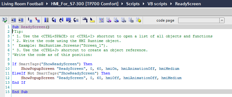
Essentially the script will check the tag in the PLC and if it is On, then the pop-up is activated. The parameters for calling the screen are as follows;
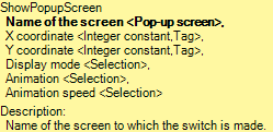
We want to set the coordinates so that it displays below the top banner at the extreme left of the screen, so our command is;
ShowPopupScreen "ReadyScreen", 0, 60, hmiOn, hmiAnimationOff, hmiMedium
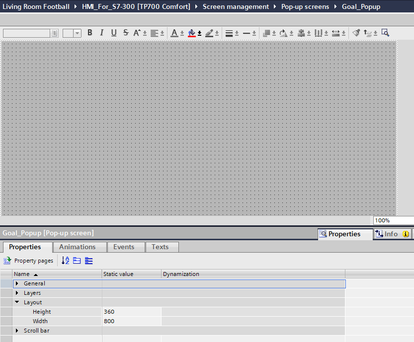
Next, we have the Goal Animation pop-up. When a goal is scored, and the score is increased, we display an animation of a goal being scored. This can be any image but we’re going to use a football one. The same as before, we set up our Goal pop-up screen and size it so it will fit between the two banners. Then we can add our image.
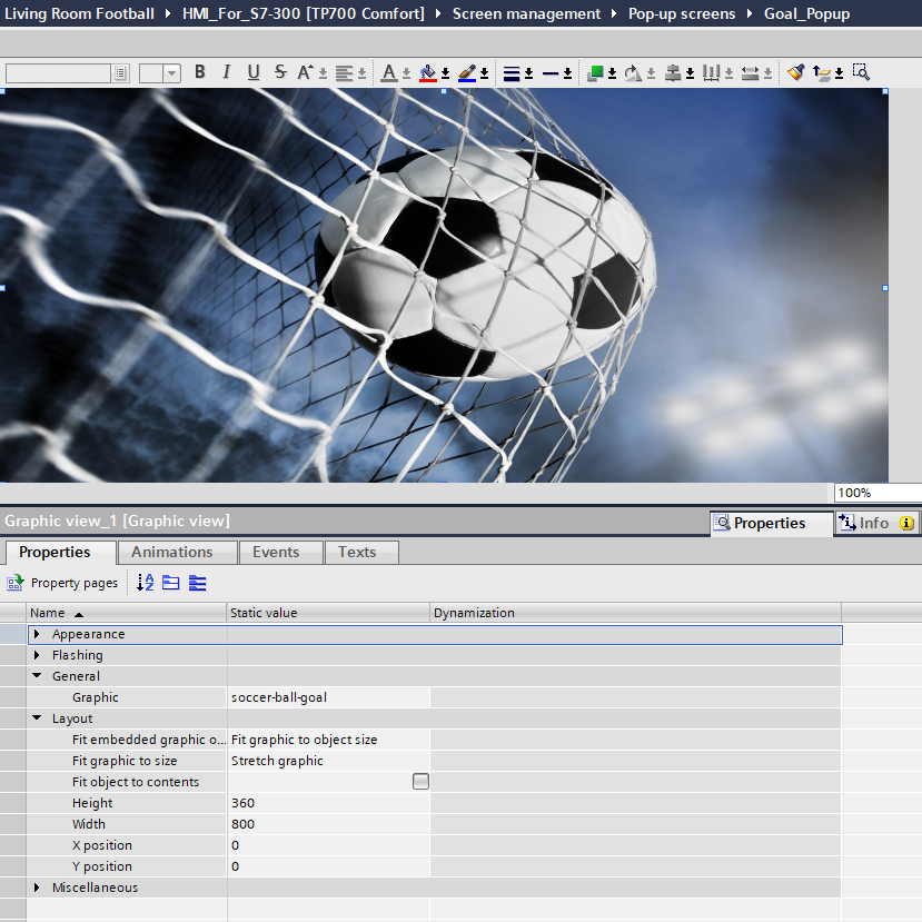
We’re once again going to use a Script to call up the pop-up. This time though, we’re going to animate it so that it appears from the left-hand side of the screen using the following command;
ShowPopupScreen "Goal_Popup", 0, 60, hmiOn, hmiLeft, hmiMedium
In the code, this will be set to be on for 3 seconds after a goal is scored using a ‘TOF’ instruction when the game is running and the score is incremented.

One thing we need to do with the tag acquisition cycle for Scripts is to set them to read the tag cyclic continuous instead of cyclic in operation. Cyclic continuous means that tags are updated continuously, whereas Cyclic in operation means tags are only updated when used on the active screen.

Downloading to the PLC
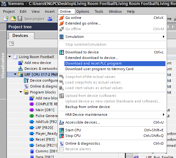
With the PLC highlighted in the Project Tree, select the ‘Online’ menu and click ‘Download and reset PLC program’. This will overwrite anything in the PLC, and download the hardware configuration and the PLC code.
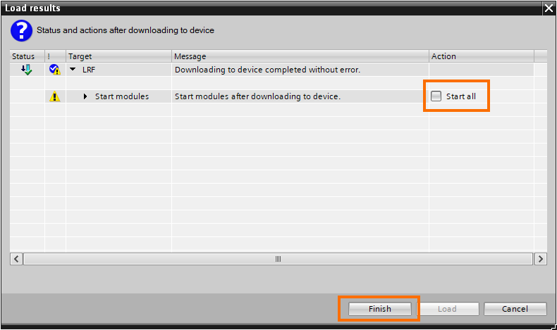
Downloading to the HMI
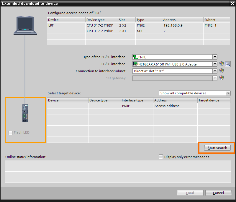
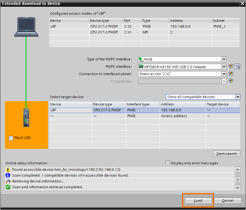
To download to the HMI, we now need to select the HMI from the Project Tree and once again go to the ‘Online’ menu and select ‘Extended download to device’. This will bring up a similar box, but we can route through the PLC to the HMI using the HMI connection we set up in Tutorial 1.
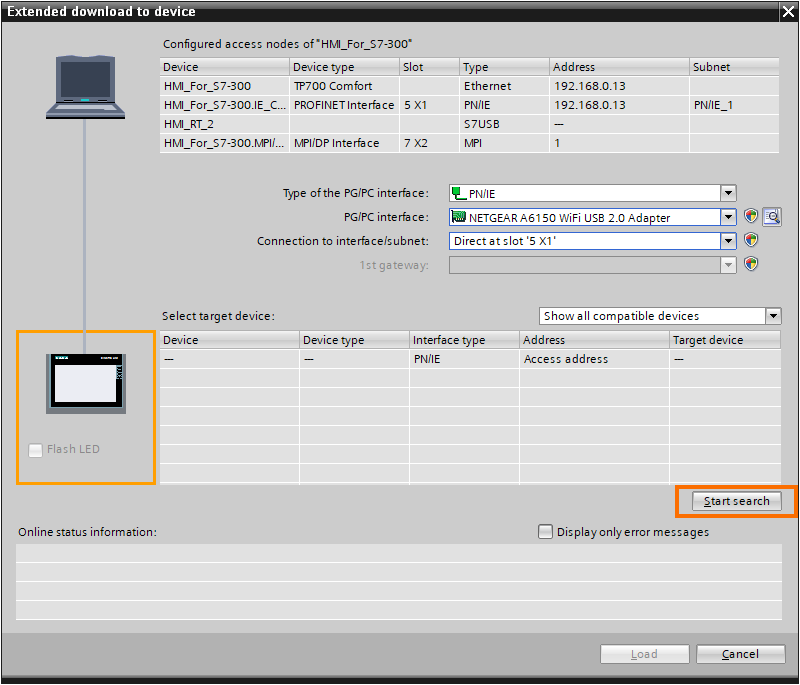
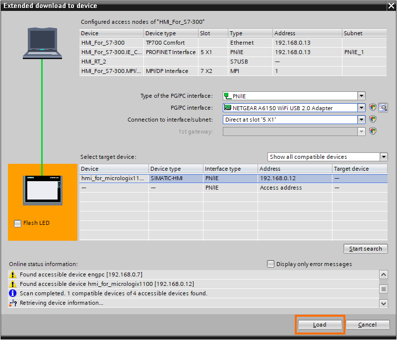
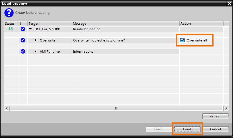
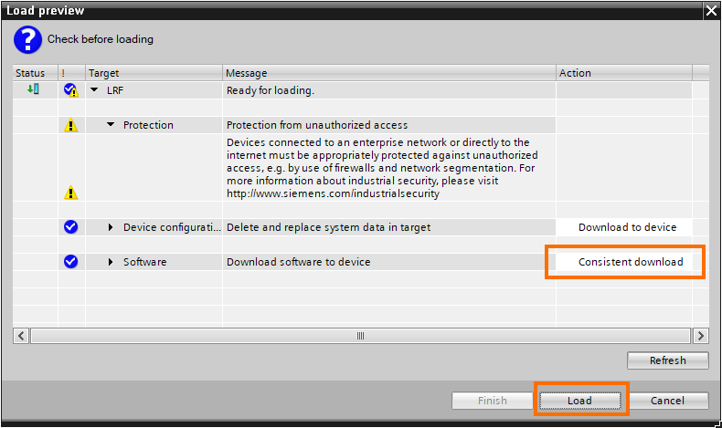
Click to overwrite the existing application and click on Load to continue.
Conclusion
In this tutorial we have designed our HMI screens, starting with the Template, then the unique screens and pop-up screens. Once we had all of the design elements taken care of, we were able to tag up all of our screens using the tags.
We wrote some VB Scripts to trigger our pop-up screens. They are read continuously from the PLC, which is different to our other tags. Only having these read continuously means we keep down the amount of read and write activities which would slow down our applications.
Finally, we downloaded our PLC and HMI applications to our devices.
