

ET 200SP Motor Starter Configuration in TIA Portal

Introduction
Motor starters are one of those components that quietly determine whether a production line runs smoothly or grinds to a halt over something as simple as a misread status flag. Anyone working with ET 200SP hardware eventually hits the same wall: the datasets are there, the function block is there, but connecting the two in a way that actually holds up on the plant floor takes more than guesswork. Skipping this groundwork tends to show up later as unreliable diagnostics or motors that won't respond the way operators expect. Getting the configuration and monitoring right from the start saves real troubleshooting time down the road.
Application Example Overview
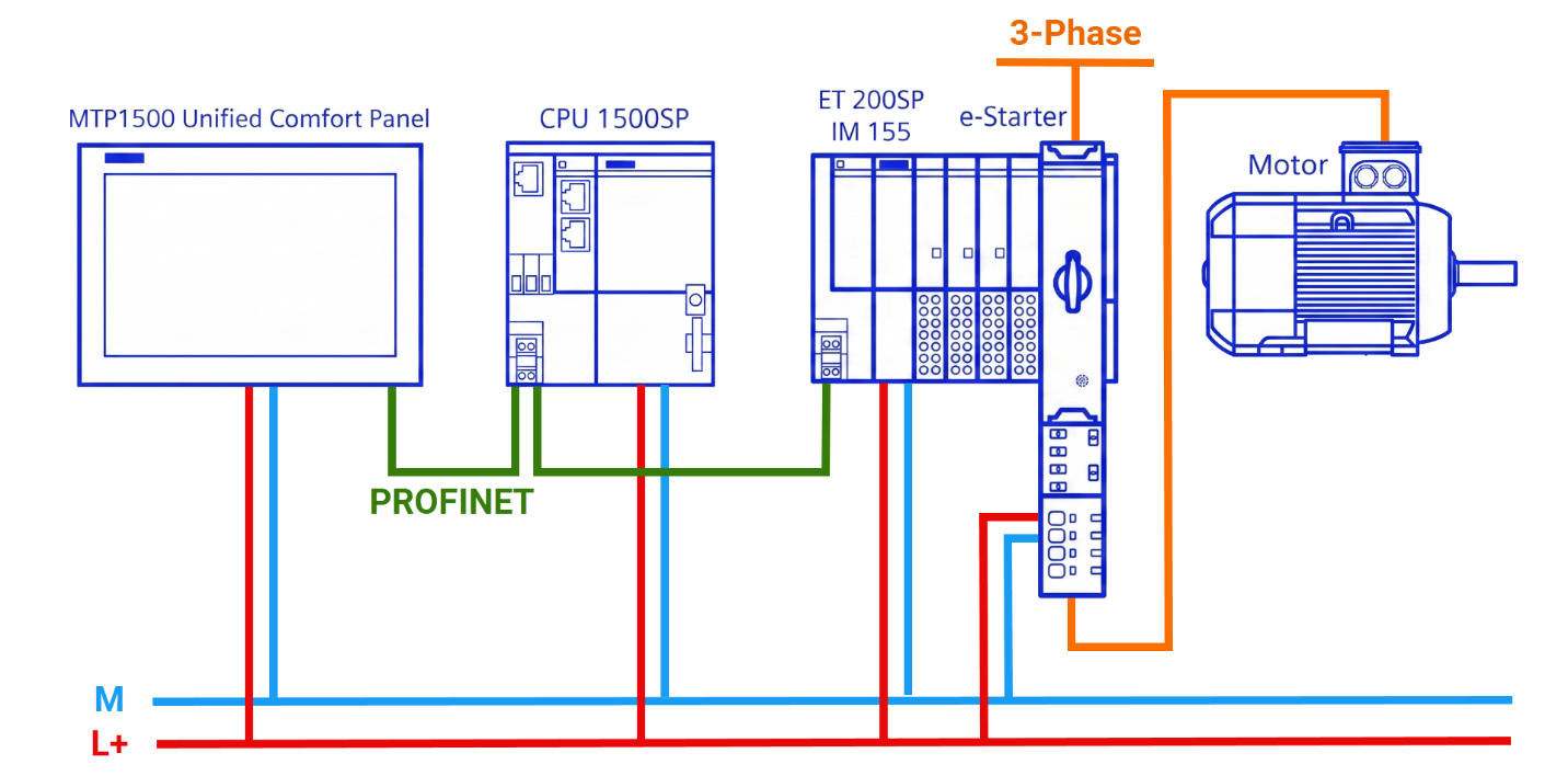
A SIMATIC ET 200SP motor starter can be configured and monitored, and that's exactly what this example covers. Depending on your setup, the gathered values show up either on the PLC itself or on the HMI too. Below, you'll find a figure illustrating a sample hardware configuration built around the motor starter. The setup calls for a pair of connections: 24-volt DC on one side, three-phase power on the other.
Engineering
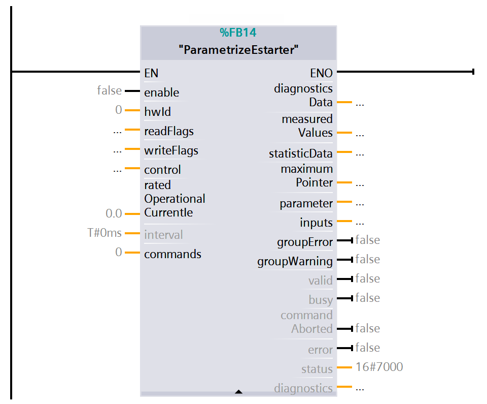
This example (you can download its library here) brings together a single central function block, multiple screens, and all datasets tied to the motor starter. 'ParametrizeEstarter' is the name given to the function block, and within it, you'll find the logic for reading values as well as writing them. You'll need to enter the Hardware ID belonging to the motor starter to operate this block. Direct motor control, along with both reading and writing, falls under what it does. There's also room to input the desired value for the operational current, plus the relevant commands. The block's output side delivers both the e-Starter's key data records and its group status, as illustrated in Figure 2.1.
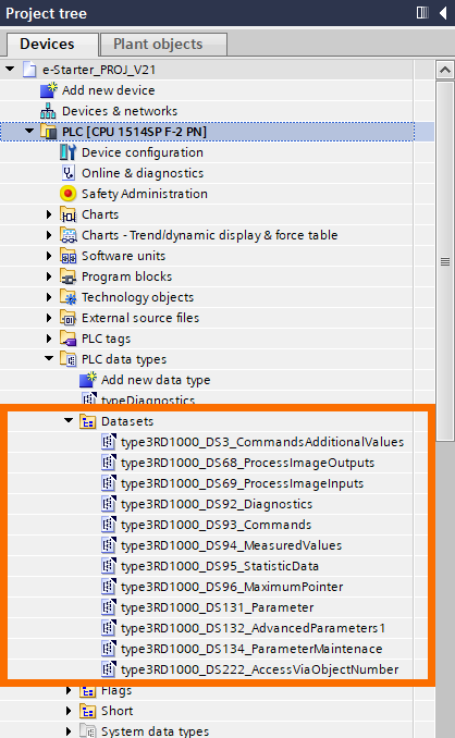
Rather than building from scratch, you can pull different values from the pre-established datasets covered in the ET 200SP motor starter documentation. Take a look at Figure 2.2 for a full view of the datasets used here. Four different categories make up the datasets in use. 'Process Image Inputs and Outputs' holds the values that set the motor in motion. 'Parameters and Access via Object Number' covers values you can both read and modify. 'Commands' can only be written and nothing else, and the remaining datasets, numbered 92 through 96 but skipping 93, are read-only.
Look inside the PLC's system constants for the motor starter, and you'll find the hardware identifier there.
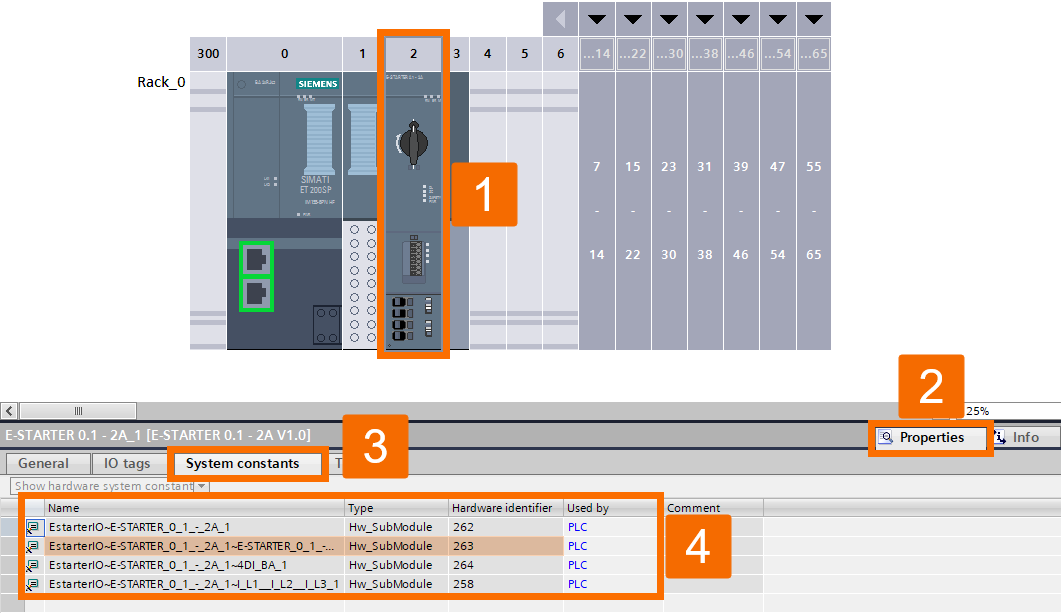
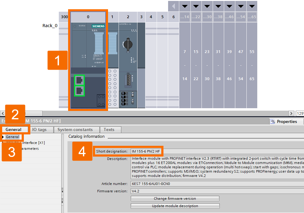
As Figure 2.4 demonstrates, an IM 155 is what establishes the motor starter connection. This setup keeps room for growth, since adding more motor starter modules expands the system with ease.
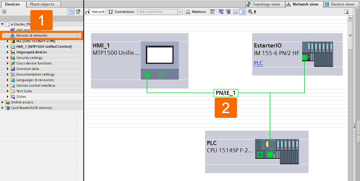
As shown in Figure 2.5, PROFINET connects the motor starter and IM 155 to a PLC, and that PLC uses PROFINET again to reach the HMI.
PLC Operation
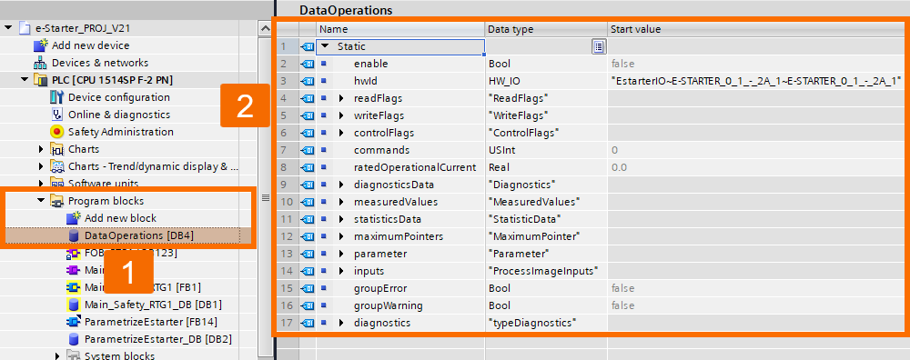
Operation occurs either straight from the PLC or via a set of several HMI screens. You'll start by covering how this works directly on the PLC. Figure 3.1 shows the 'DataOperations' data block, the source of the values sent to the function block, all of them editable.
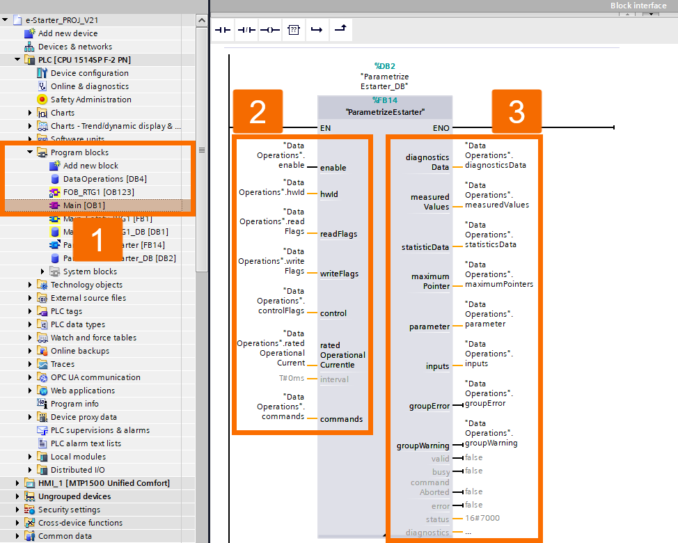
The link between the function block's inputs and outputs and the 'DataOperations' global data block variables is mapped out in Figure 3.2.
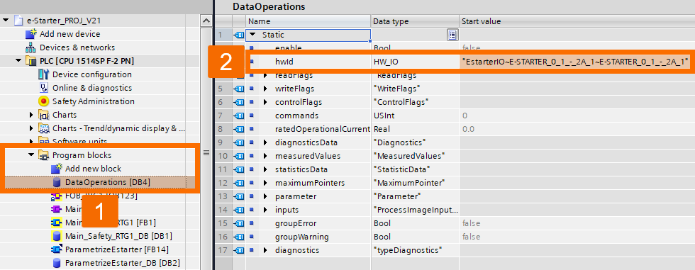
Do you know the reason why the function block relies on the hardware ID? Because it's the key to fetching values from the right device. That value pointed out in Figure 3.3 is where the Hardware ID goes.
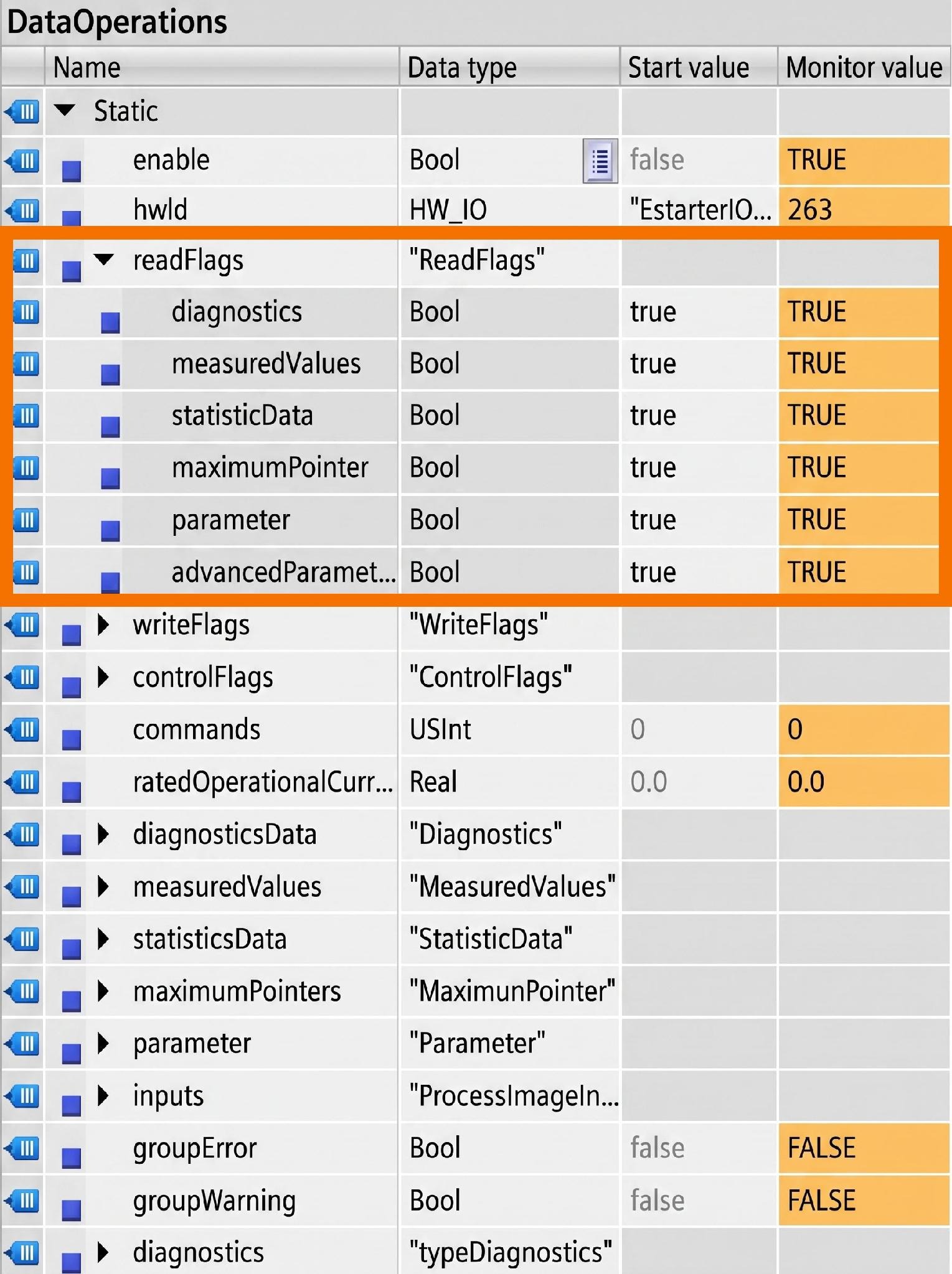
You obtain the motor starter's values through a read operation performed by the function block. Several datasets are the source of these values. The 'ReadFlags' variables are the mechanism used to turn on reading for these datasets. Expand the data type, and the variables tied to their respective dataset names come into view, as shown in Figure 3.4. Whichever dataset you set to TRUE is the one that starts being read.
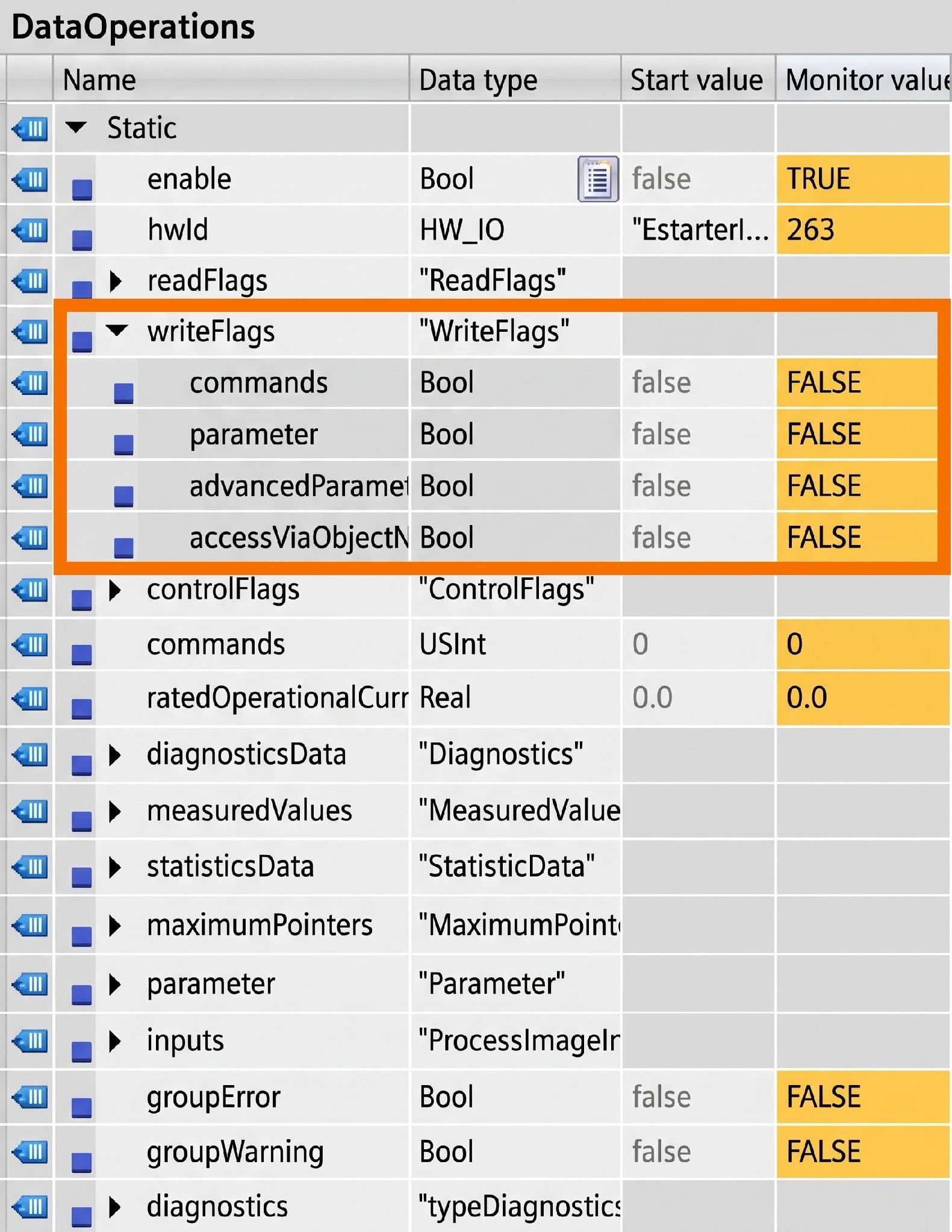
Value writing into the datasets stays inactive unless it's switched on through the 'WriteFlags' variables. The variables tied to writable datasets are all contained in this specific data type. Figure 3.5 illustrates the step needed to activate writing, which is flipping the variable to TRUE.
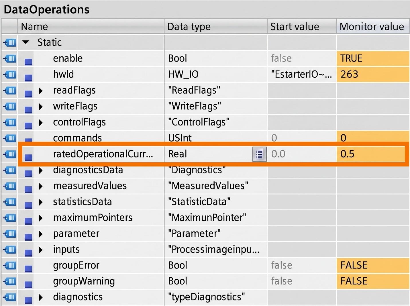
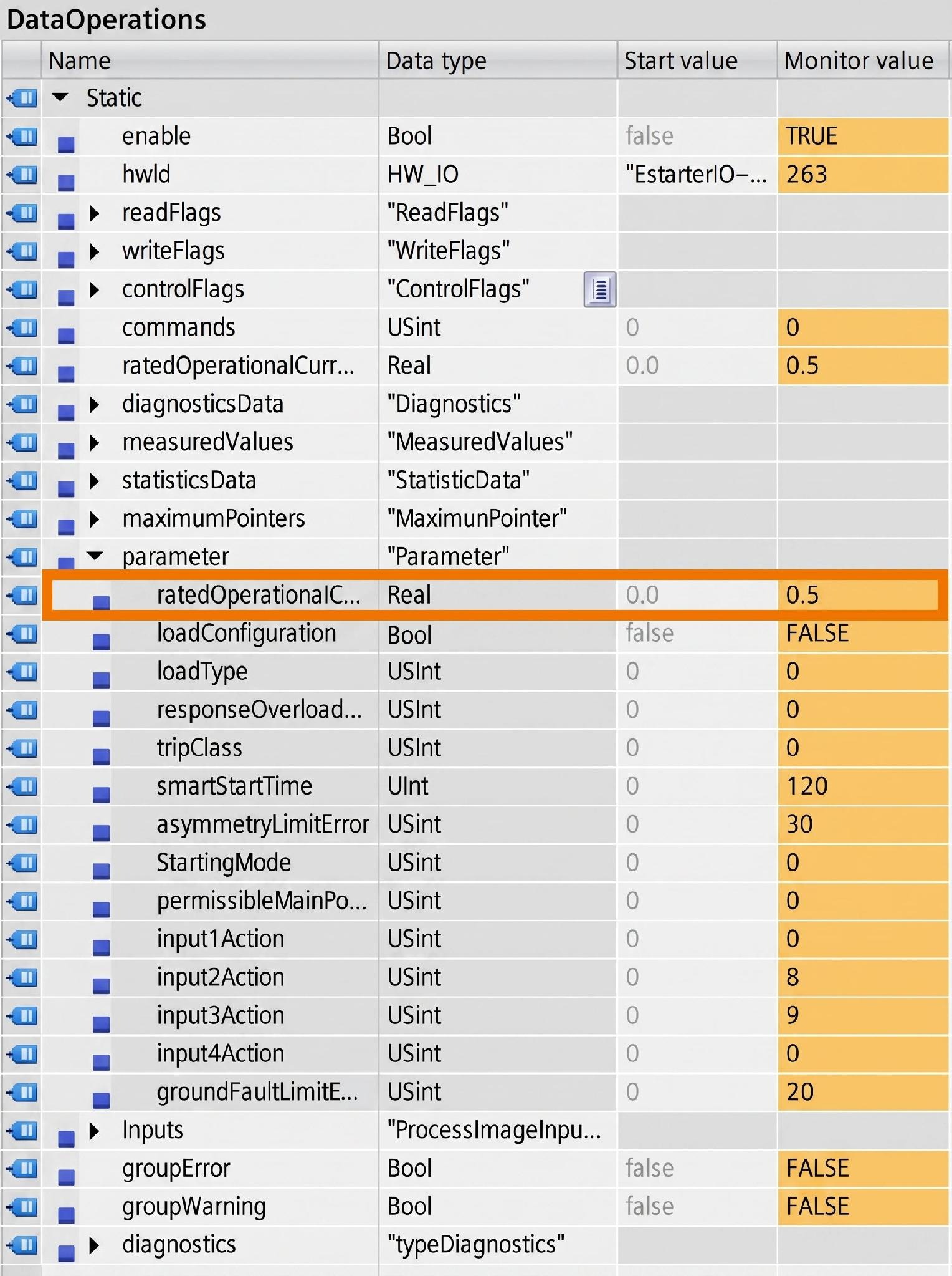
Reading the dataset is how the operational current, which already has a value assigned, gets retrieved. The 'ratedOperationalCurrent' variable, pointed out in Figure 3.6, is where the new value needs to go to change this parameter.
With the new value in place, writing needs to be executed next, as shown in Figure 3.7.
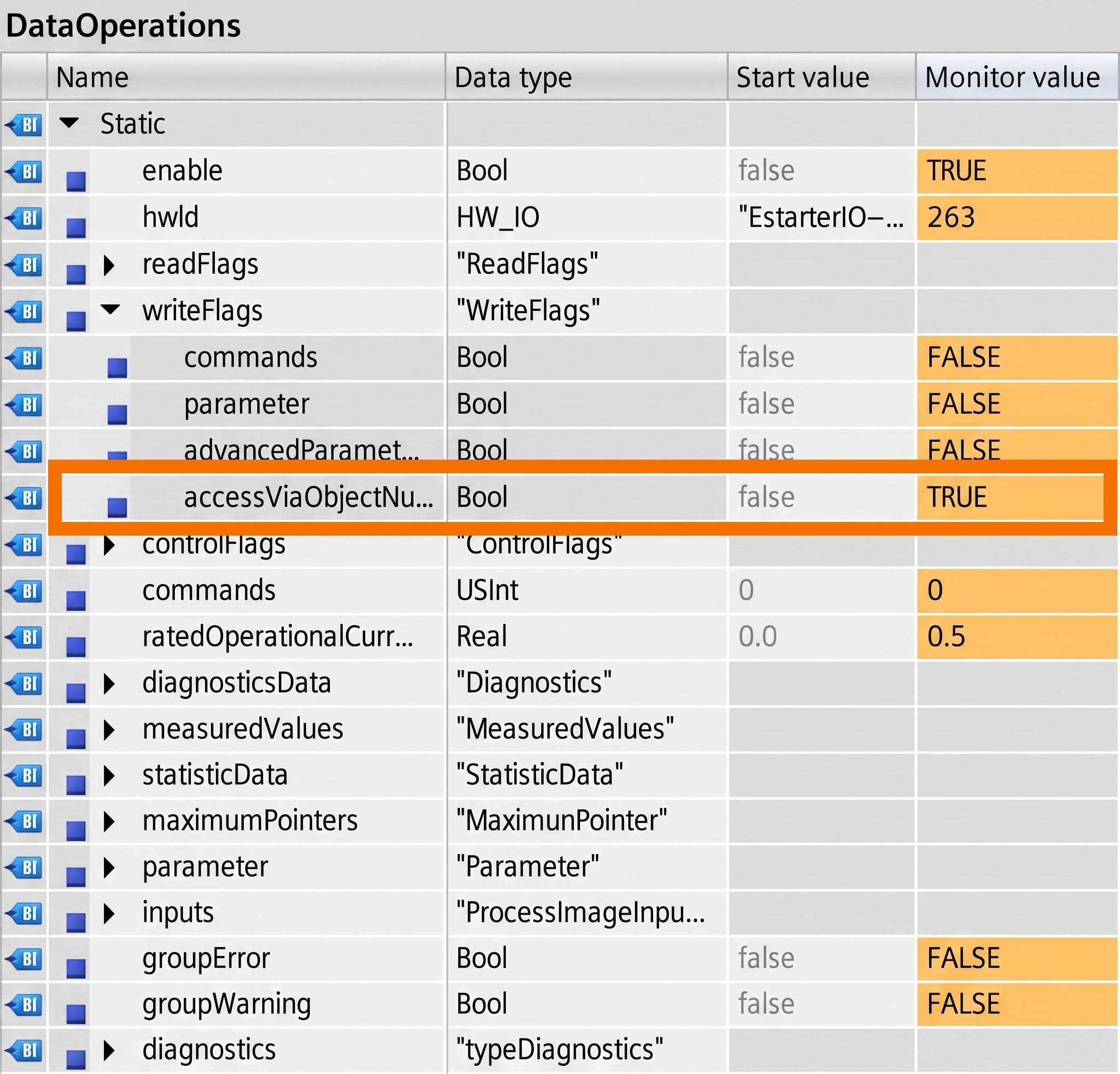
The variable matching the dataset parameter's name is where you'll check the newly changed value, pictured in Figure 3.8.
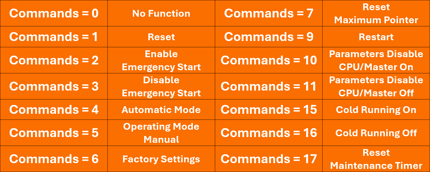
You can only write to the command dataset, never read from it. Figure 3.9 lists the actions you can trigger, depending on the value you write.
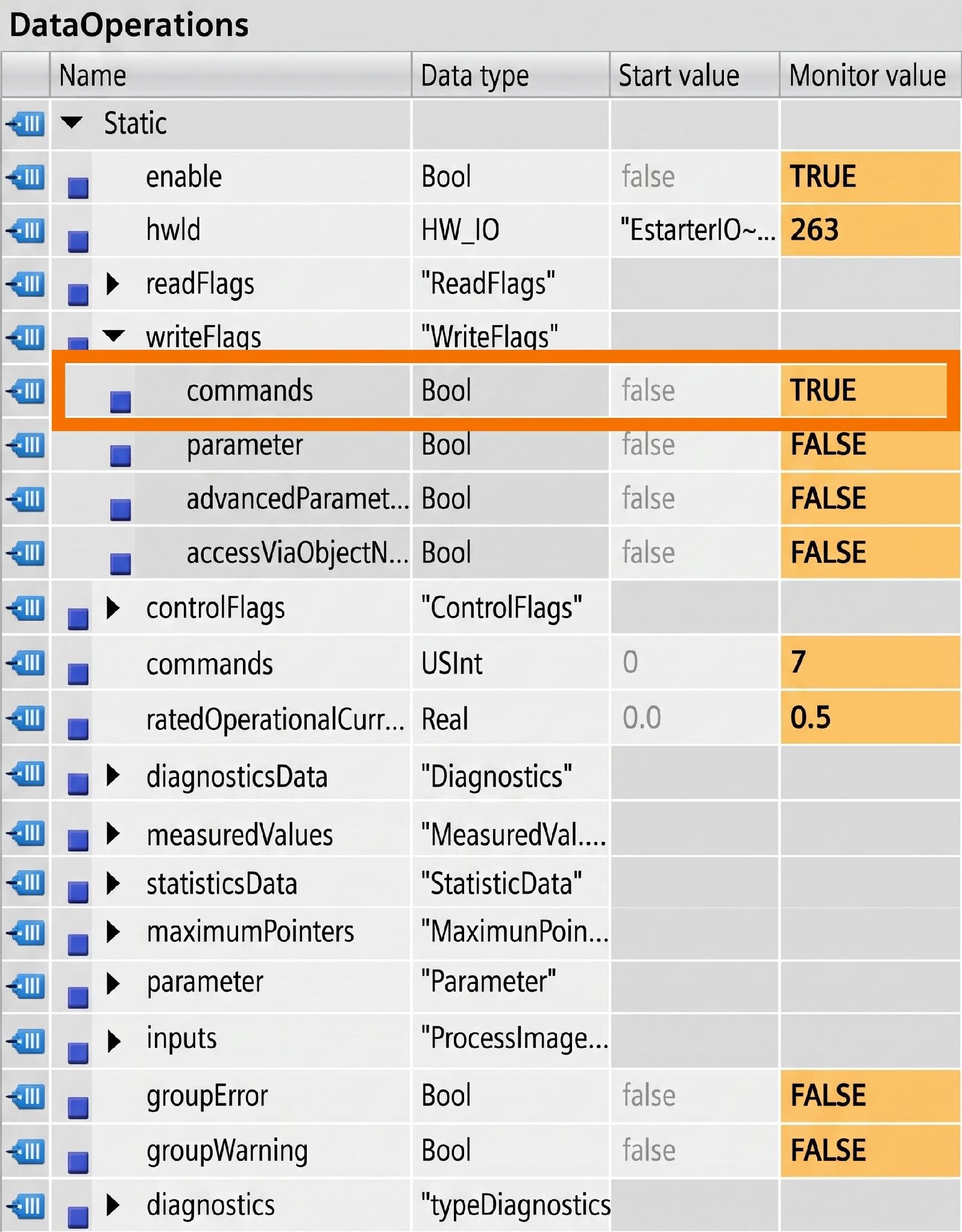
The commands variable, shown in Figure 3.10, is where you place the value before writing it.
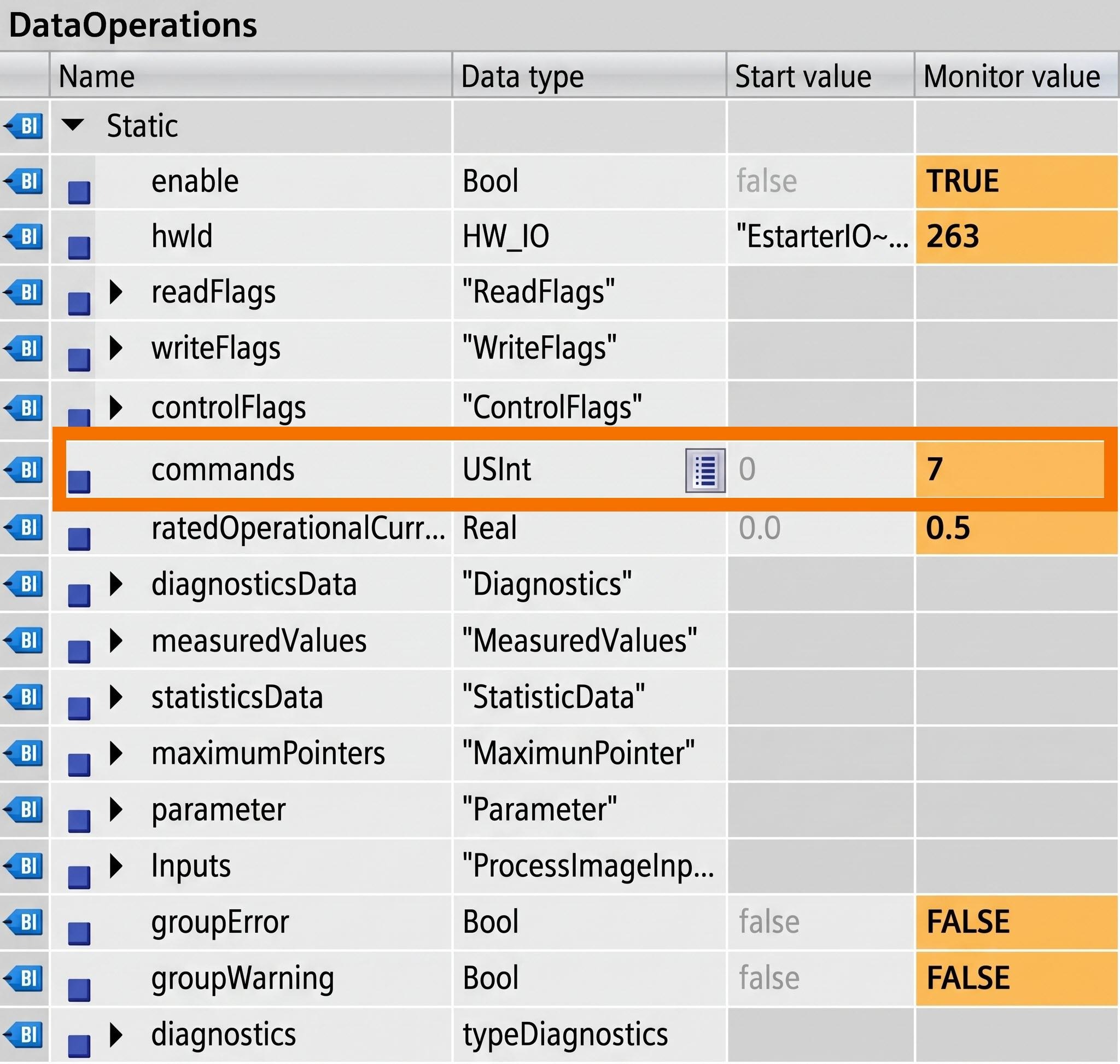
Execution of the writing follows right after the new value goes in.
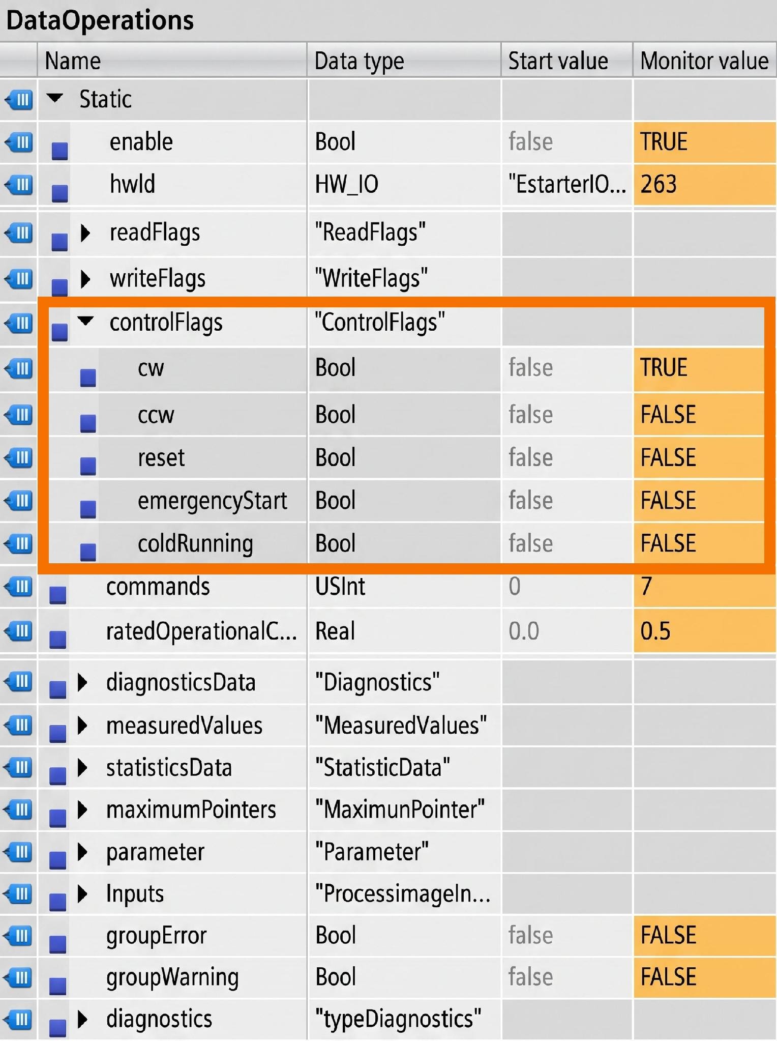
That motor linked to the motor starter falls under the direct control of the function block. You can see the motor-control variables the moment the 'ControlFlags' data type gets expanded. Setting these variables to TRUE gets things started, exactly as CW does in Figure 3.12. The motor can be started in one of two directions: CW turns it clockwise, while CCW turns it counterclockwise. Both variables need to go to FALSE if you want the motor stopped.
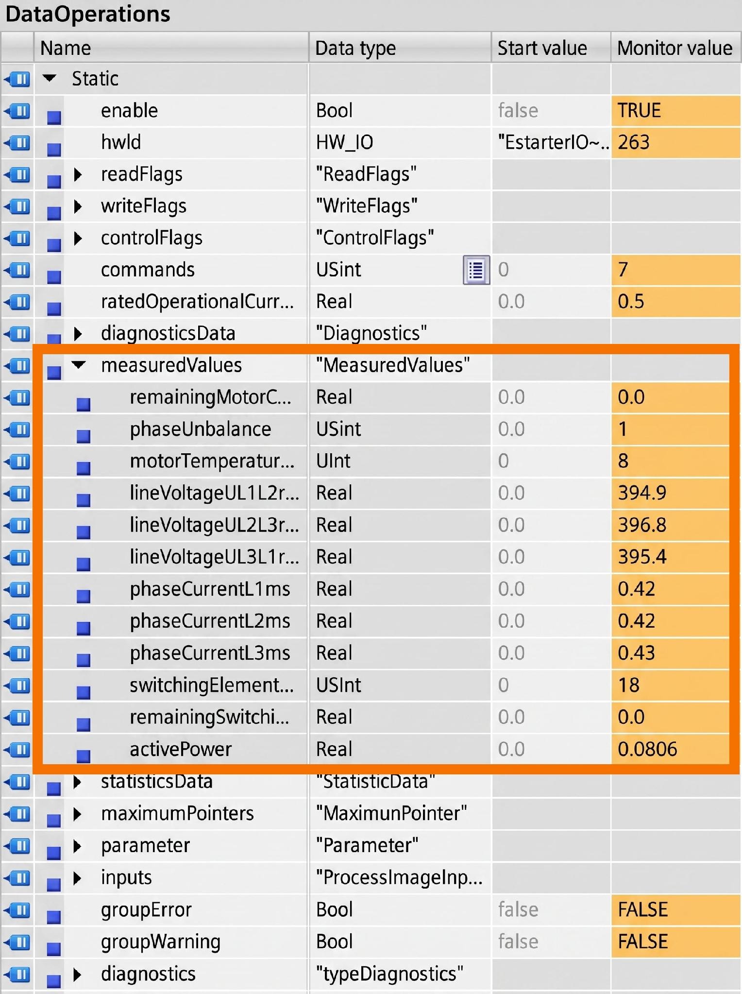
What comes out of the function block are the datasets' relevant values, each one organized under its own corresponding dataset. 'Diagnostics', 'Measured Values', 'Statistics Data', 'Maximum Pointers', and 'Parameter' each display their relevant values as soon as they are expanded.
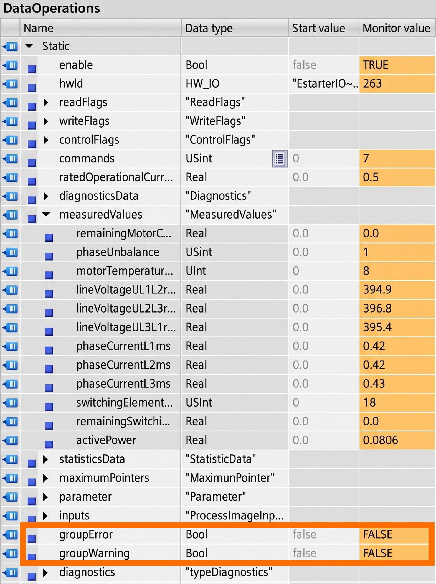
The function block additionally outputs signals for group status, flagging either a 'Group Error' or a 'Group Warning'.
HMI Operation
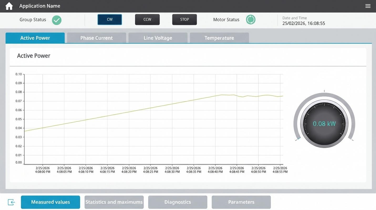
There are eight screens total that make up the HMI program. The read-out information from the motor starter's datasets appears here, across these screens. Beyond viewing, you can write parameters and control the motor's start and stop operations.
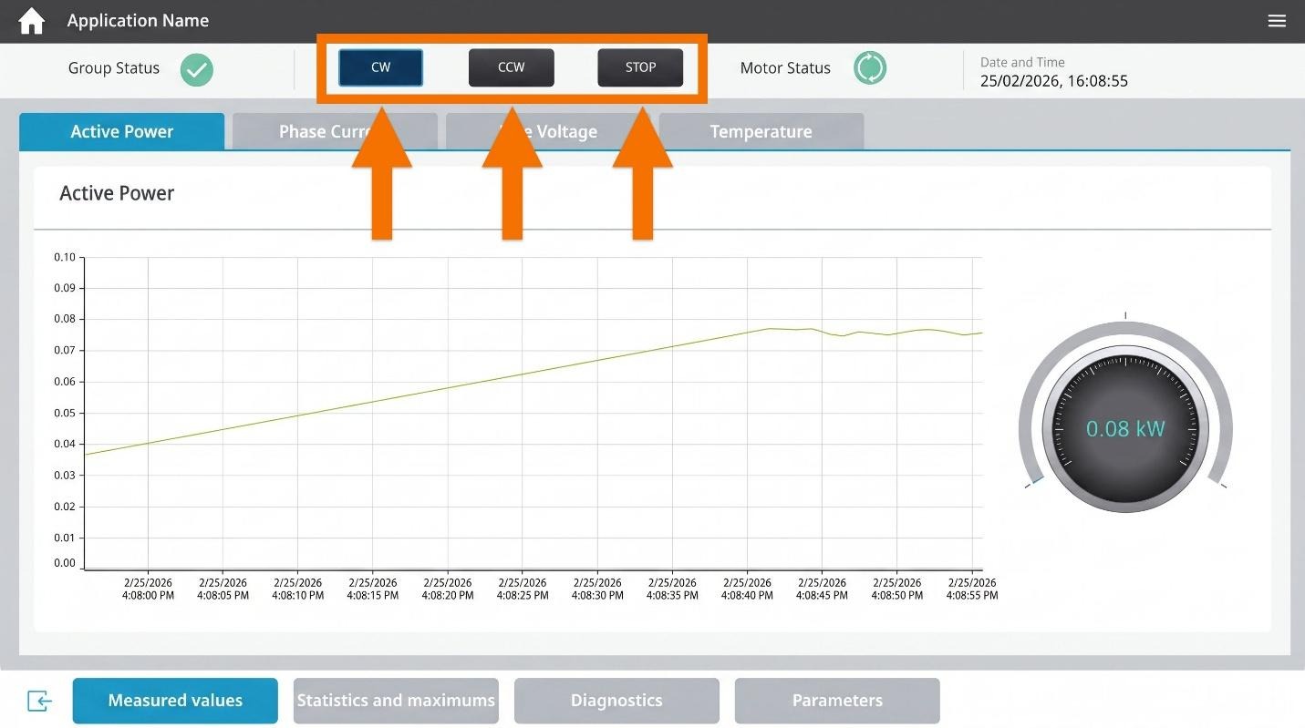
Pressing the buttons shown in Figure 4.2, which are located in the header, changes the motor's status.
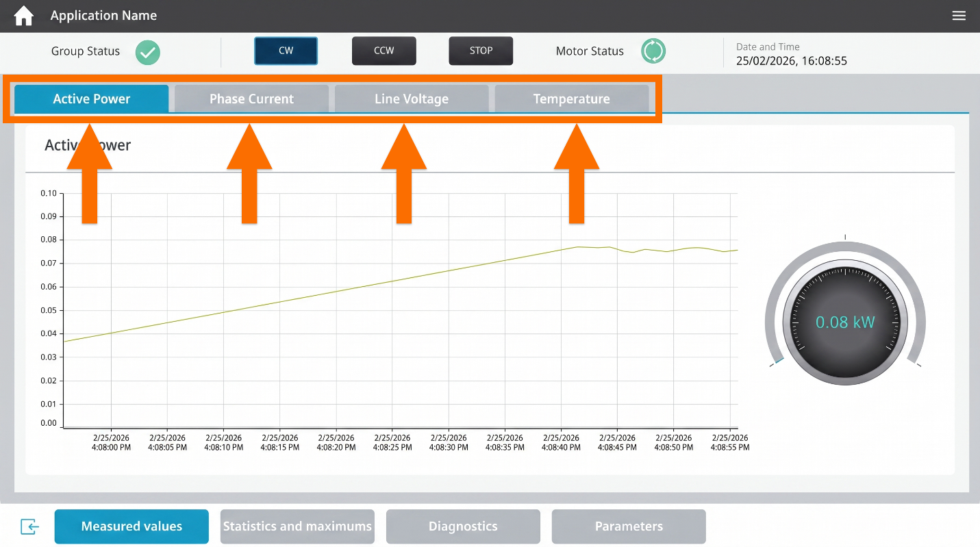
The 'Measured Values' section includes table navigation, pictured for reference in Figure 4.3. You can browse those values across four tabs for a clearer picture.
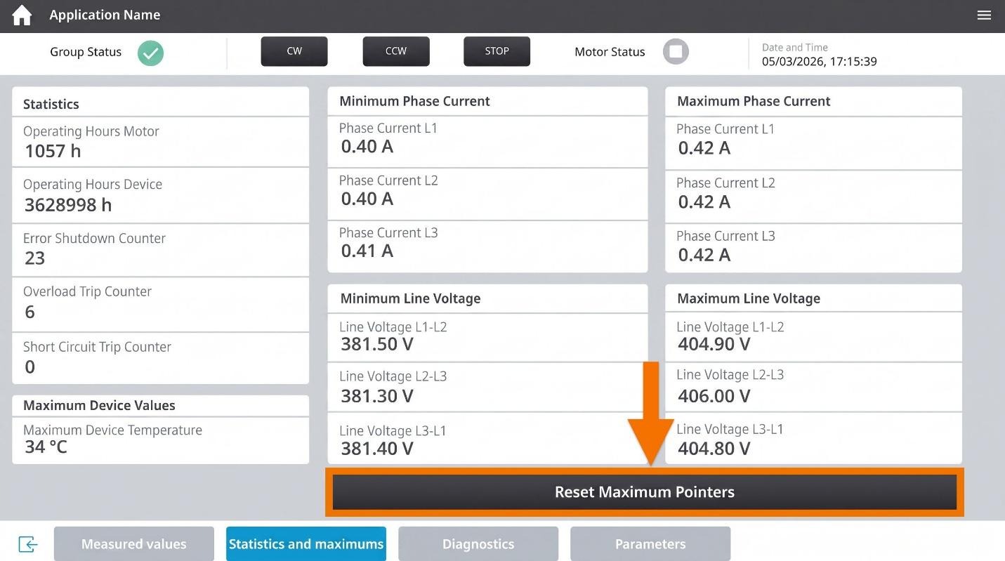
You will find both statistics and maximum pointer values grouped on one screen. You can reset the maximum pointer values using a button located on the screen.
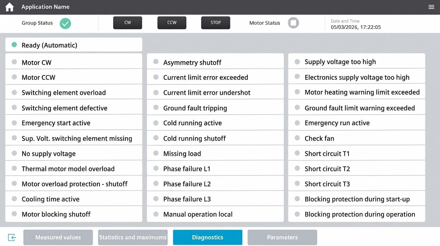
All relevant diagnoses live on the 'Diagnostic' screen, and its activation depends on the status. Green, yellow, and red are the three possible colors for the status light, based on the diagnosis.
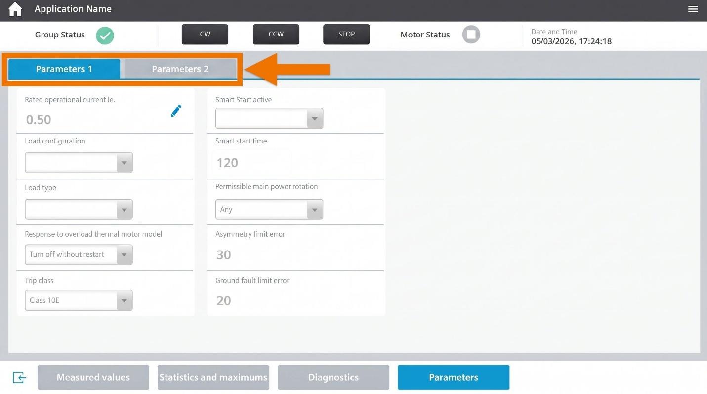
Parameter values are displayed across two separate screens dedicated to the 'Parameters' area. You get to these screens by using table navigation.
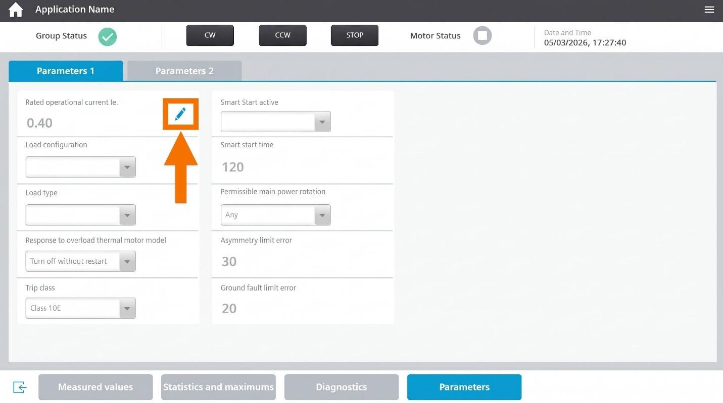
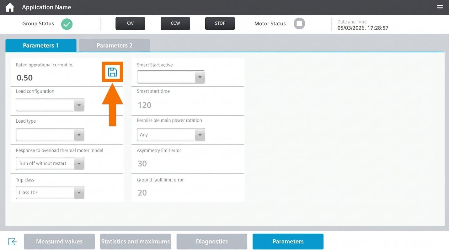
The 'Parameters' screen lets you input a value for the Rated Operational Current. Start by hitting the pencil icon.
Then the value becomes editable. Once you've changed it, press Enter on your keyboard.
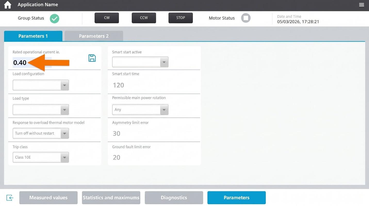
Finally, tap the save symbol to lock it in.
Error Handling
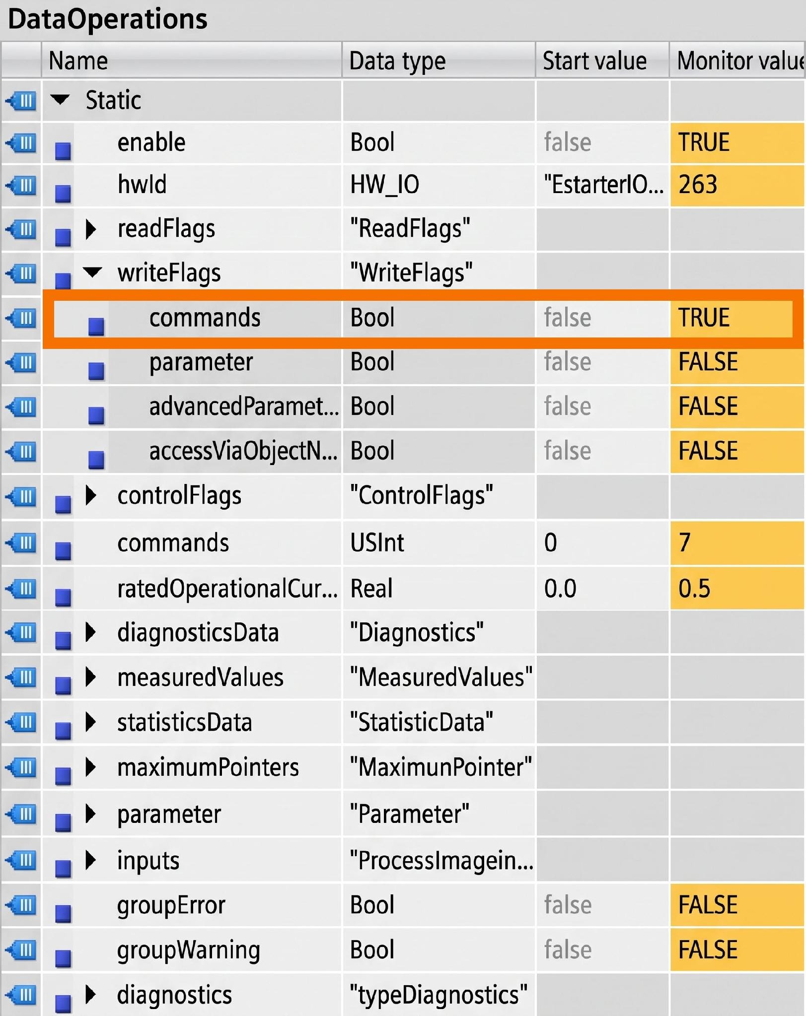
If the motor starter shows a general error, resetting the module fixes it. To reset the module, just set the 'Commands' variable's value to 1.
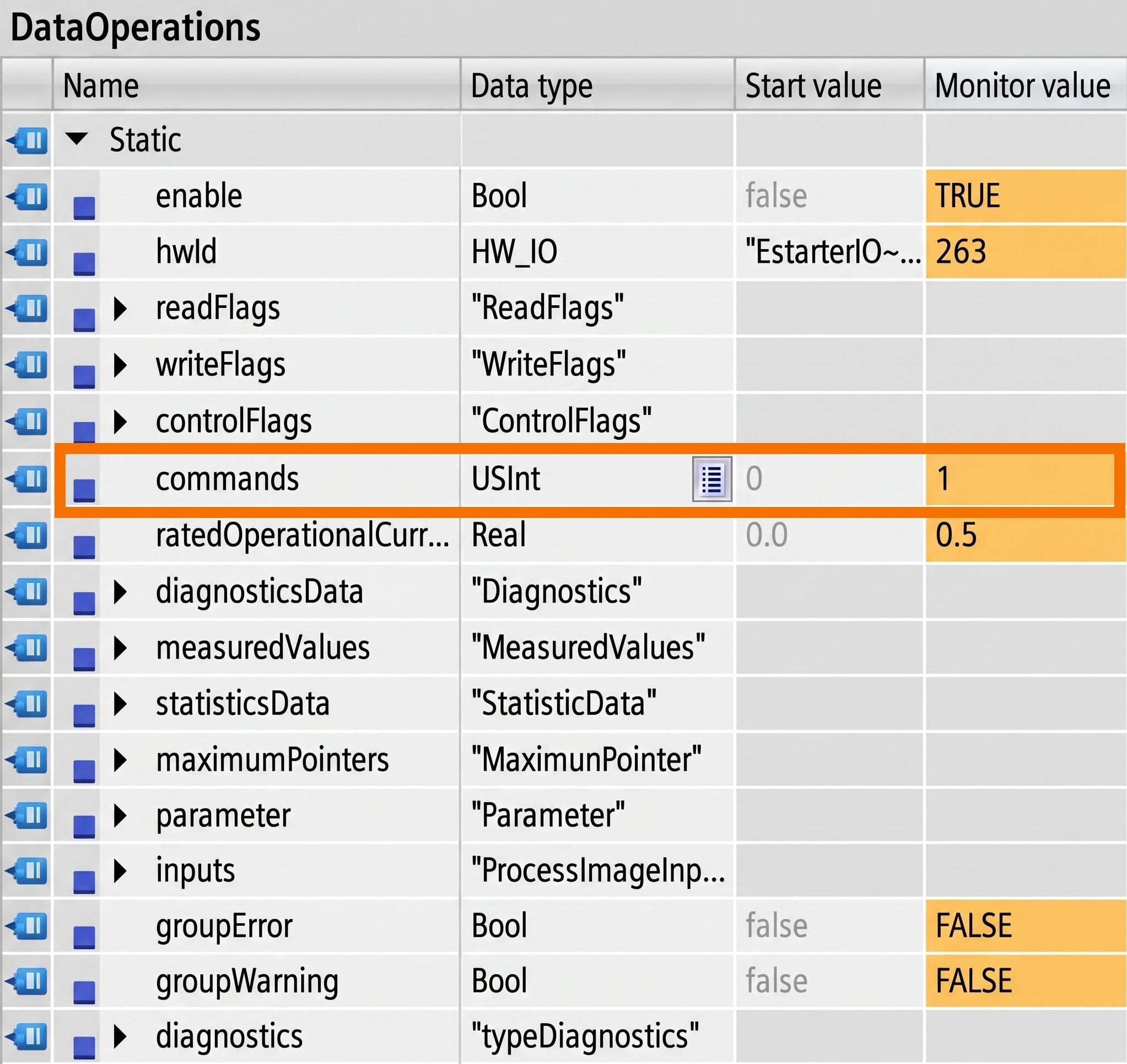
After setting it to 1, the value gets read following the same steps covered earlier.
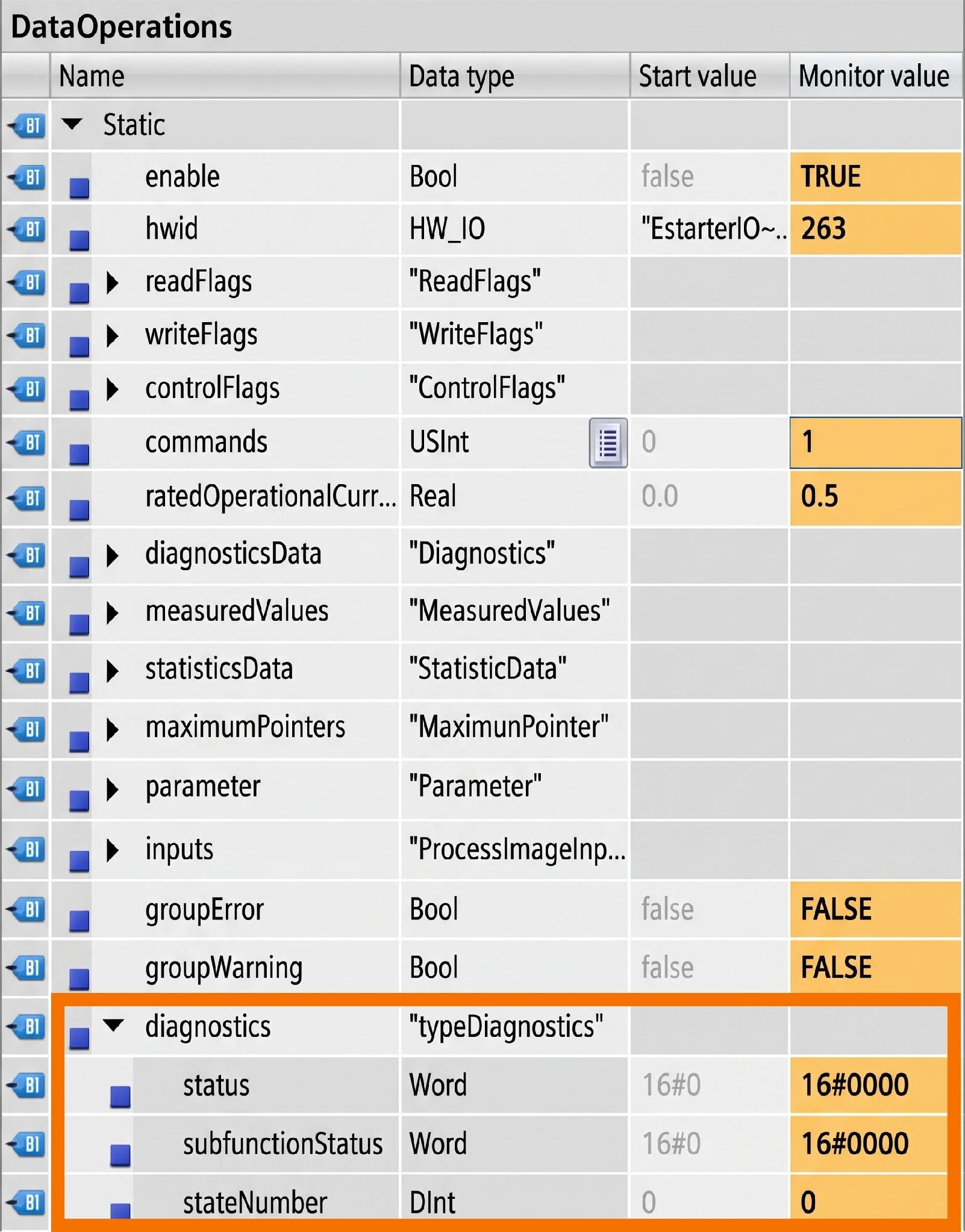
The 'DataOperations' holds the diagnostic status inside its 'Diagnostics' variable. The status keeps you informed about the program's condition and flags any errors that occur.
Conclusion
In conclusion, you have learned how to configure and monitor a SIMATIC ET 200SP motor starter using the specific function block, including how the Hardware ID links the block to the correct device. You've seen how to read and write dataset values through the ReadFlags and WriteFlags variables, adjust the rated operational current, issue commands, and control motor direction with CW and CCW. You also walked through monitoring diagnostics, measured values, statistics, and maximum pointers across the HMI screens, along with resetting the module after a general error. With this foundation, you're ready to apply the same workflow to your own motor starter configurations.


