Groov EPIC | PAC Controller Setup and Input / Output Sequence Programming Tutorial

Groov EPIC PAC Controller groov Manage
In our previous tutorial on the groov EPIC PAC Controller, we’ve unboxed the unit and looked at some of the basic hardware features. Today, our goal is to create a simple control sequence through the PAC Controller interface and demonstrate the interaction the controller can have with the field hardware.
To follow along, you may download a free copy of the PAC Controller Basic directly from the Opto 22 website: PAC Control Basic Download
Groov Manage Online Interface
When the groov EPIC controller is set up, it’s possible to give it an IP address on either or both interfaces. It’s possible to complete the following steps through the integrated LCD, but connecting to the Programmable Automation Controller (PAC) makes them much simpler.
Step 1 - Set an IP through the LCD
- From the “Home” screen, Press on “System”
- From the “System” screen, Press on “Network”
- From the “Network” screen, change the IPv4 and Subnet Mask of “Ethernet 0” (and/or “Ethernet 1”).
In our case, we’ve decided to set Ethernet 0 to 192.168.1.101 /24 as shown below.

Step 2 - Connect to the groov EPIC
- Connect an EtherNet cable (RJ45) from your groov EPIC to your laptop. Note: there may be a switch in between the two. We’re using a Stratix 5700 series managed switch.
- Open a Chrome (or any other browser) session and type in the IP you’ve set in “Step 1”.
- Accept the “non-secure” connection if prompted.
If the connection is properly established to the controller, you should see a familiar “Home” screen through your browser.
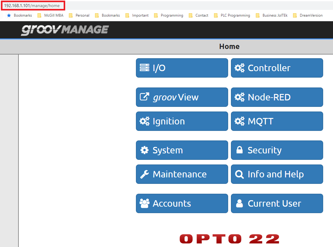
Step 3 - Verify that PAC Controller is enabled
- From the “Home” screen, press on “Controller”.
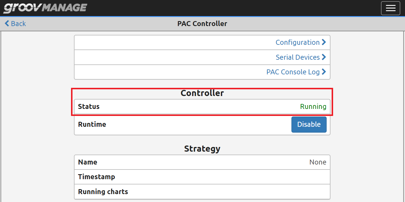
- From the “Controller” screen, press on “PAC Controller”.
- On the “PAC Controller” screen, verify that the Controller Status is set to “Running” per the screenshot below. This feature should be enabled by default on the groov EPIC
Working with PAC Control Software
Pac Control software comes in two versions: free and paid. The current price for the Pro license is $399.00 USD when purchased directly from Opto 22.
To download the software, follow the link posted above. Note that you may download the Pro version, but will need the license to use it with your controller. For the purpose of this tutorial, we will stick to the Basic version of the software. Please find the link to download at the start of this tutorial.
Once downloaded and installed on a windows machine, the user will be presented with a simple interface through which one can write Programmable Logic Controller (PLC) logic.

Adding the groov EPIC PAC and IO points to the Software
We start by creating a new program for our controller; in the “PAC Control” software, these blocks are called “Strategies”. Click on “File”, “New Strategy…” and select a file location.
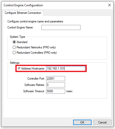
Once the strategy is created, we need to link to our controller. Click on “Configure”, “Control Engines…”. From this menu, the user is invited to add a controller that will be programmed and use the strategy. Input the same information we’ve configured during the setup process.
The next step is to add the IO points we have attached to our controller. Depending on what you’ve purchased, the modules may differ. In this tutorial we’re exploring the groov EPIC Learning Center (Part Number GRV-EPIC-LC) which includes 4 points of IO external to the controller. These cards may be automatically recognized by the controller or manually added. It’s important to understand both as you may not have access to the controller during development of the software.
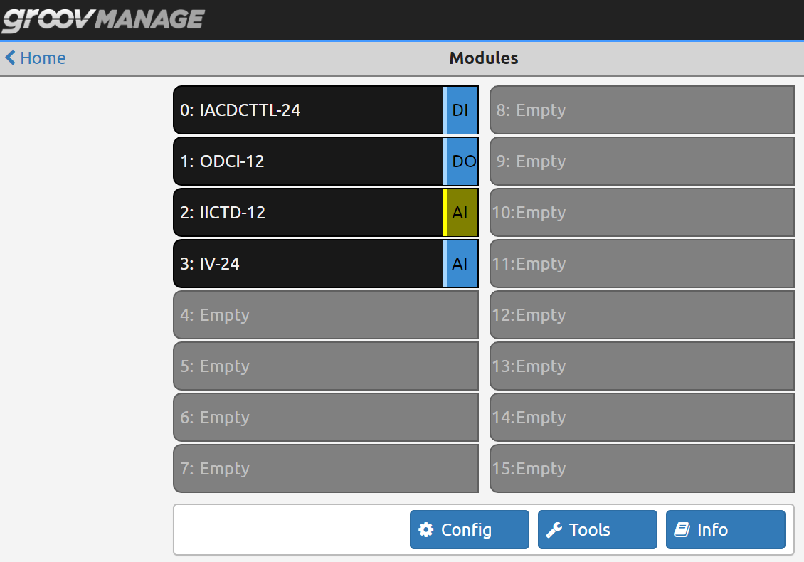
Here’s how to identify the cards you have through the groov Manage application we looked at earlier.
- From the “Home” screen, Press on “I/O”
- Confirm each module through the groov EPIC Online Catalog. See Example below that covers the 4 cards included with the Learning Center.
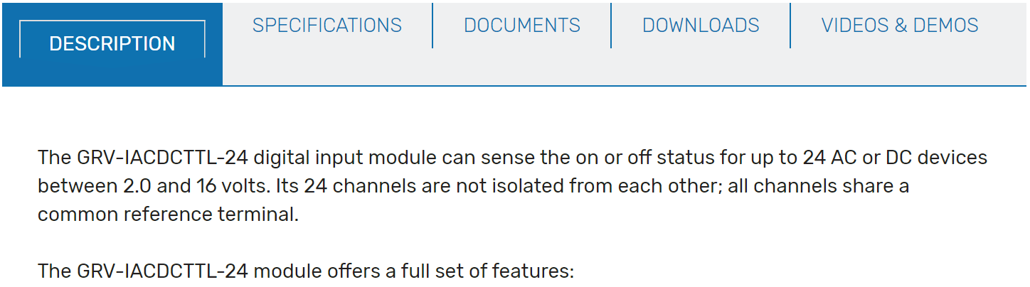
By searching for the first module in our list, we can find additional information through the Opto 22 website. This information is critical for knowing how to integrate external devices into the card, adding it into our software tree and general information about the price, availability and specifications.
Adding the Module Into PAC Control
In Pac Control, open the “Configure I/O Units” interface through the “Configure” menu. At this point, navigate to the “I/O Modules and Points…” menu, select an unused slot and press “Add..”. You can choose from a wide array of input and output cards the specifications of which you can find through the Opto 22 website. Add all the cards you’re planning on using in your system.

Building a Basic Conditional Sequencer in PAC Control
Now that we’ve configured the IO points, it’s time to create a “Hello World” equivalent of PLC programming. We will be utilizing one input and one output card in order to create a simple sequencer that will flash 6 LEDs on the output card when the input is energized through the existing button on the groov EPIC controller.
Step 1 - Adding a “Main Program” Chart and Transition
The Strategies in PAC Control contain “Charts” that are executed in the order specified by the program. By default, the controller strategy will launch the “Powerup” chart that is initialized in PAC Control when you create the strategy. In order to execute other charts, the user has to create them and specify the transitions from the “Powerup” chart into any subsequent chart. Here are the basic steps on how to get this done:
- Right-click “Sharts” in the Explorer Menu and select “New…”.
- Give your chart a name and press “Ok”.
You should now have a new chart within your folder.
Step 2 - Creating a Transition between Charts
As mentioned above, a transition will allow the controller to execute the specified chart.
- Add an “Action Block” through the top menu.
- Add a connection from “Block 0” to the new block by using the “Connect Tool”.
- Double-click the new block.
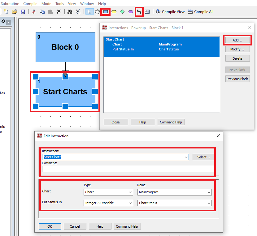
- Create a new function by pressing “Add…”.
- Choose the type of instruction to be “Start Chart”.
- In the “Name” field, select the chart you created in the previous step.
- Add an Integer 32 Variable that will hold the current value of the chart. You’ll have to create a new variable after you confirm the action.
Step 3 - Creating a Conditional Block for the Input
Our sequencer will wait for the “Start” button to be pressed and then cycle through 6 outputs of the groov EPIC PAC.
- In the newly created chart (We’ve labeled ours “MainProgram”) add a Conditional Block that will be used to check for the button press.
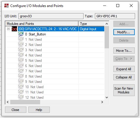
- Right-click the “Modules and Points” folder in the IO tree.
- Expand the input card.
- Add a label to the first input that isn’t used and label it. (We’ve labeled ours “Start_Button”)
- Double-click the block.
- Click “Add…”
- Select Instruction of type “On?”
- Select the input you’ve configured in Step 2.

- Add a connection from “Block 0” to the new block by using the “Connect Tool”.
Step 4 - Cyclical Validation
The program should only execute when the input is pressed. Therefore, we need to create a loop that will keep the sequence in this condition while the button isn’t pressed.
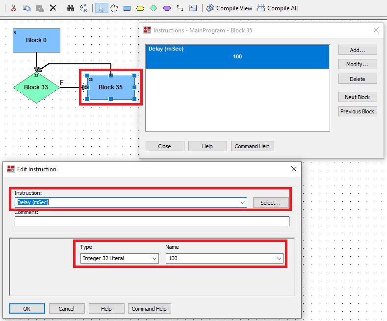
- Add an action block.
- Double-click the block.
- Click “Add…”
- Select Instruction of type “Delay (mSec)”
- Specify a 100 mSec Integer 32 Literal.
- Add a connection from the conditional block to the new block by using the “Connect Tool”. Note that you will need to select the “False” condition as we want the loop to execute while the button is NOT pressed.
- Add a connection from the new block back to the input of the conditional block.
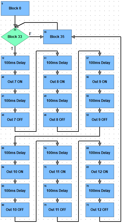
Step 5 - Sequencer Setup
Our goal is to cycle through 6 outputs on the output card. Start by adding them to the appropriate IO points within the IO tree. In our case, we’ve labeled them from 1 to 12.
- Create a series of ON / OFF blocks (as specified below) to turn on the outputs in a sequence broken down by delay timers.
- Add a sequence of ON and OFF blocks to create a sequence for each output that will be turned on and off.
Here’s the final outcome that will accomplish what what described at the beginning.
Running the Sequence on the Opto 22 groov EPIC PAC Controller
Now that we’ve finalized the sequence, it’s time to load it onto the controller. By selecting the
“Debug” mode in the top left corner of the editor, we can load the program into the specified controller. At this stage, we can step through the program to figure out if it’s doing what we expect. Finally, we can go into the “Online” mode to finalize the program and run it continuously on the controller.

Conclusion
The Opto 22 groov EPIC Programmable Automation Controller (PAC) is capable of running a PLC program created within the PAC Control software out of the box. By configuring the Network settings of the controller, the user is able to verify the status of this tool through the web interface of the controller. A controller may be used to be part of or interface with a DCS or Distributed Control System.
By downloading the free or paid version of the PAC Control software, we can connect to the controller, specify the IO cards in the module and create a simple sequence that’s the equivalent of a “Hello World” application in the automation world. However, through this exercise, we’re learning how to build conditional and action blocks through the PAC Control software.
