

How to Control a Dahlander Motor with an Electronic Starter

Introduction
If you're working with Dahlander motors or planning to automate motor control, understanding how to use an electronic motor starter is a game-changer. This tutorial will guide you step by step, from the basic principles of Dahlander motor operation to the practical wiring and programming of the ET 200SP e-Starter. By following along, you'll gain hands-on knowledge of safe pole-changing, speed control, and directional switching, integrated into TIA Portal. Even if you've worked with traditional starters before, this tutorial will show you a faster, smarter, and safer way to control your motor while reducing wiring complexity and avoiding common electrical pitfalls.
Prerequisites
What you will need to follow along with this tutorial:
- A clear understanding of basic PLC motor starter logic, including start/stop circuits. Review "PLC Interview Questions – Building a 2 Button Motor Starter System" if needed.
- Working knowledge of Structured Text and Boolean interlocks. Refer to "Structured Text Logic and Boolean Instructions | Motor Starter Interview Practice" before proceeding.
Electronic Motor Starter
The motor starter applied throughout this tutorial is the ET 200SP e-Starter, an electronic and space-saving solution for motor control. It combines measuring, supervision, protection, and switching functions in one compact housing. By utilizing modern circuit design, it integrates various switching and protection mechanisms. Furthermore, it includes integrated electronic short-circuit protection as part of its functionality.
Electronic vs Traditional Motor Starter
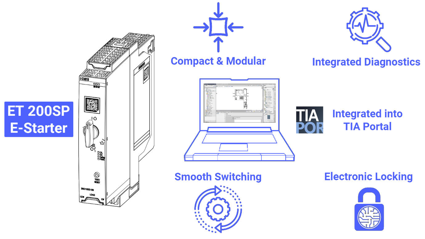
It is time to examine the advantages of the ET 200SP e-Starter over conventional switching technology. Compact and modular, it requires far less space than traditional contactors and circuit breakers. The device provides integrated diagnostics, including current monitoring for protection, fault detection, and cycle tracking, unlike conventional solutions that rely on external components. For safety, the e-Starter integrates electronic locking with enable contacts, whereas traditional systems require mechanical interlocks. Its switching is smooth, with defined pauses, compared to the mechanical wear-prone operation of conventional starters. Fully integrated into TIA Portal, it eliminates the need for additional programming, enabling intelligent control, fast diagnostics, and reduced wiring complexity.
How Dahlander Motor Works
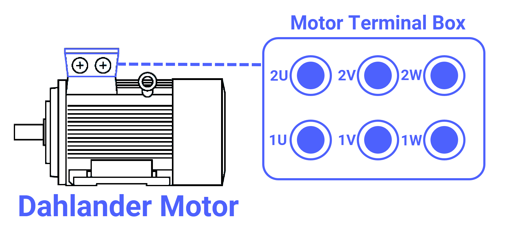
The Dahlander motor, known as the two-speed motor, represents a sophisticated solution for applications that require variable mechanical output from a single machine. The magic of the Dahlander design lies in its use of a single winding that is electrically regrouped into different internal circuits. This transformation is made possible by the presence of six winding ends accessible within the terminal box, specifically labeled as 1U, 1V, 1W, and 2U, 2V, 2W. By manipulating the physical connection of these six terminals, you can change the motor's internal pole count since the number of poles is the primary governor of rotational speed.
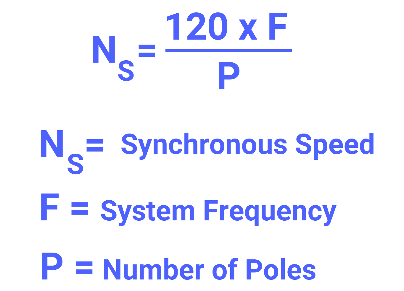
In the study of induction motors, speed is governed by the synchronous speed formula, which illustrates the rigid relationship between the frequency of the power supply and the electromagnetic layout of the stator. This formula highlights an inverse relationship. As the number of poles increases, the speed of the motor decreases, and vice versa.
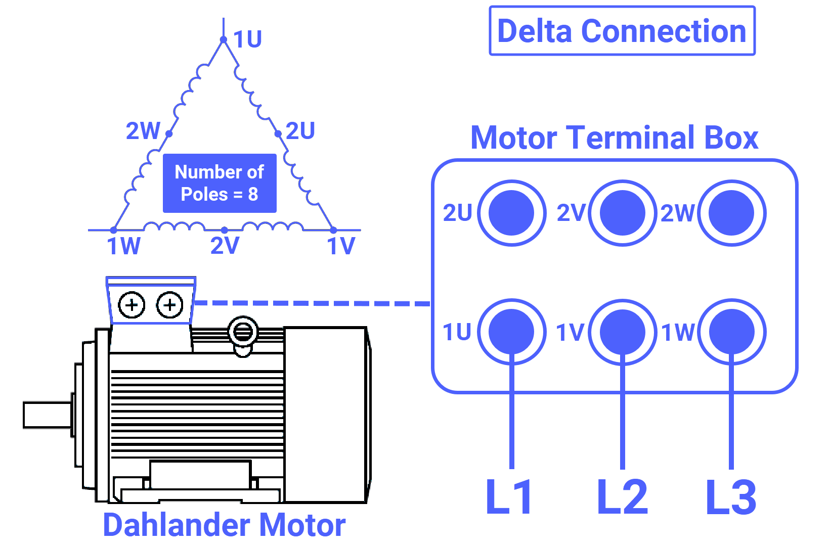
To engage the Dahlander motor's low-speed feature, the internal windings must be arranged in a Delta connection. Inside the junction box, the wiring command for the technician is precise. three phases of the power supply (L1, L2, L3) connect directly to terminals 1U, 1V, and 1W, and terminals 2U, 2V, 2W remain open and disconnected. This specific arrangement creates an 8-pole stator field. While this provides the necessary low-speed rotation, be aware that this is the motor's least efficient state. To transition from this low-speed state to maximum performance, you must completely re-route the flow of current through the windings.
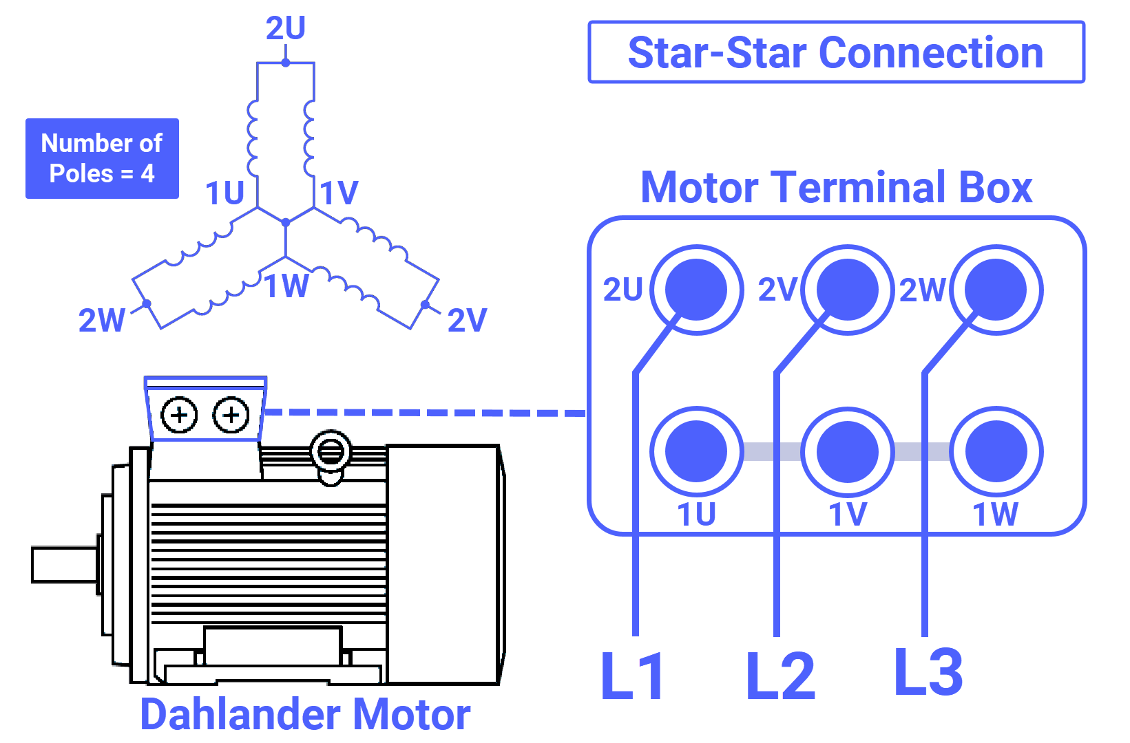
Achieving the high-speed feature requires a physical transformation into a Double Star (also referred to as Star-Star or YY) connection. It requires a systematic two-step reconfiguration. First, you need to relocate the power supply. Move the incoming lines (L1, L2, L3) from the primary terminals to 2U, 2V, and 2W. Secondly, establish a common point. To do this, create a short circuit between terminals 1U, 1V, and 1W. This common point is typically created using copper shorting links or jumpers provided by the manufacturer within the terminal box. Ensuring these links are securely torqued is critical to preventing phase imbalance. The result of this connection is the formation of two parallel windings arranged in a star shape. This configuration reduces the effective pole count to 4 poles, allowing the motor to reach its high-speed rating.
Wiring Diagram: Dahlander Motor with ET 200SP E-Starters
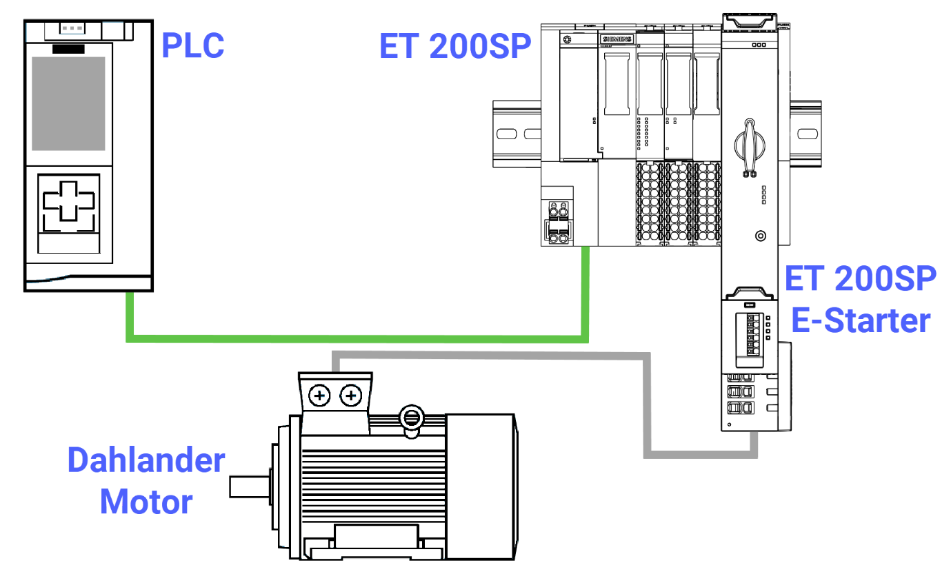
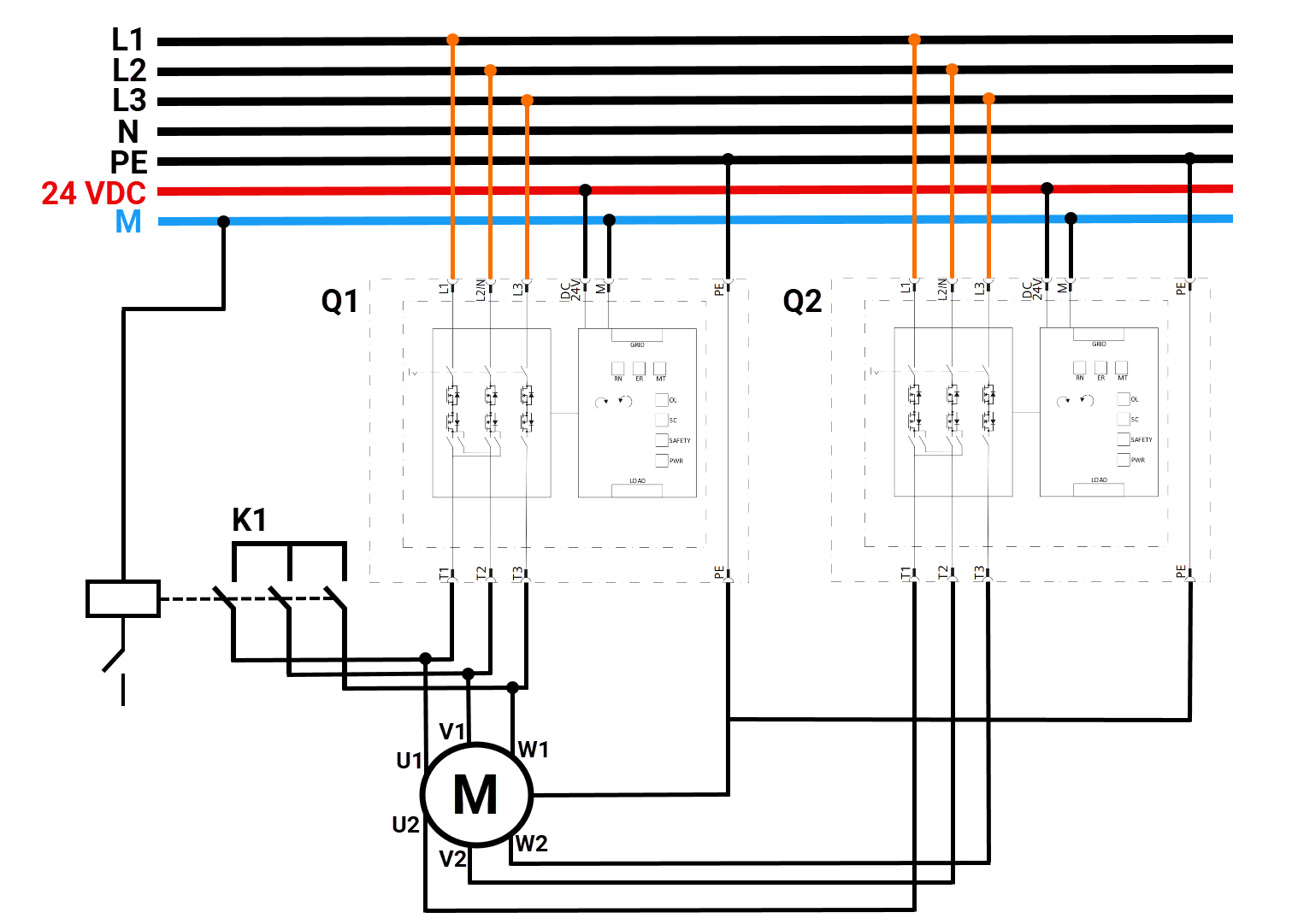
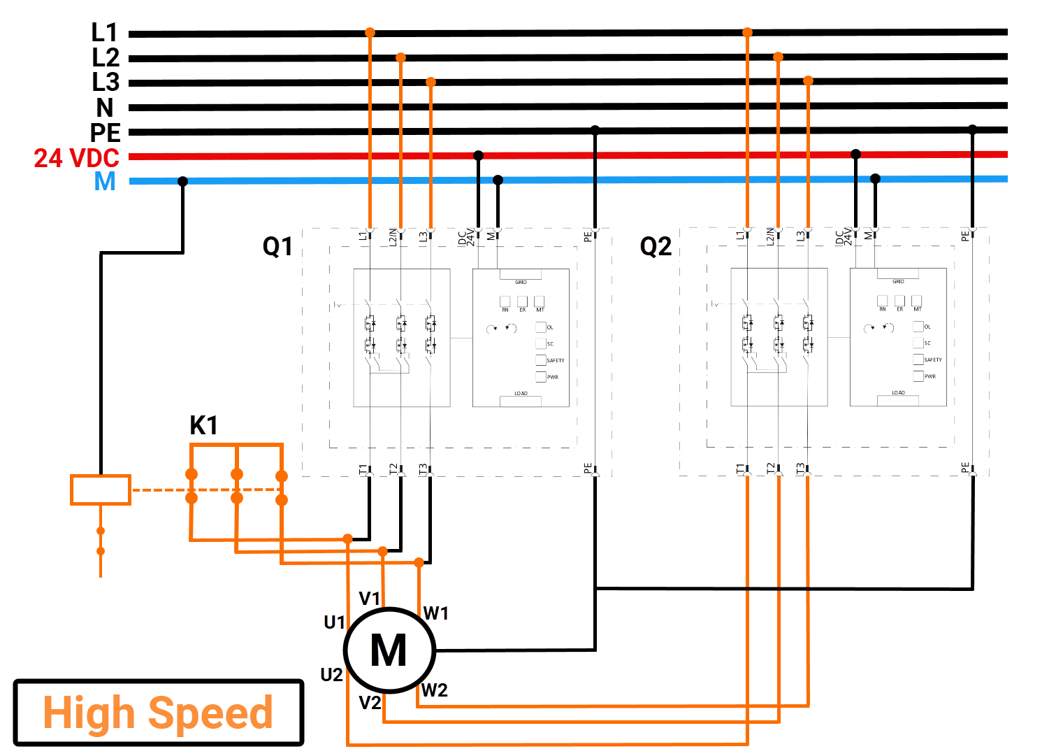
The wiring diagram illustrates a typical Dahlander speed changeover sequence. The shown configuration operates without direction reversal, although the associated TIA Function Block also supports reversal via phase sequence switching. The system consists of two ET 200SP e-Starters, identified as Q1 and Q2, and one mechanical contactor, K1, which is used for pole reconfiguration during the transition to high speed. The sequence begins in the de-energized state. In this initial condition, both e-Starters and the contactor are open, meaning no supply voltage is applied to the motor terminals. As a result, the motor remains completely de-energized and stationary.
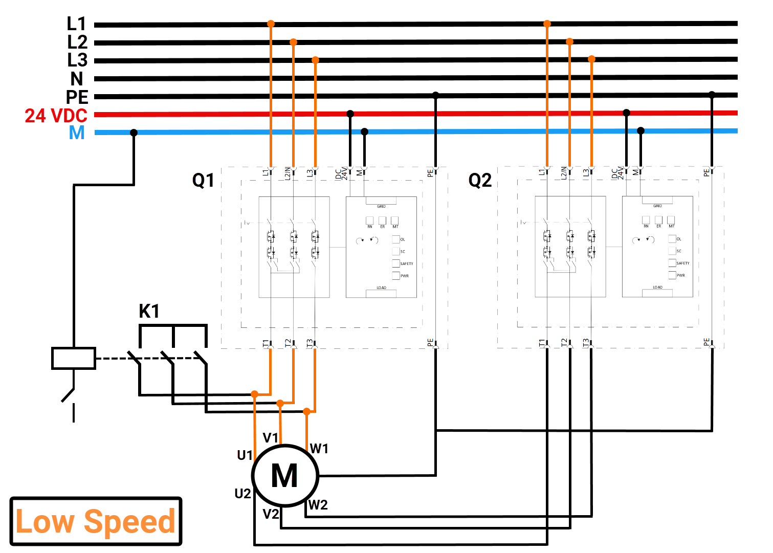
When low-speed operation is initiated, e-Starter Q1 is activated. Referring to the wiring diagram, the three-phase supply from terminals T1, T2, and T3 of Q1 is connected to the motor’s U1, V1, and W1 terminals, respectively. In this configuration, the Dahlander winding is arranged for the lower pole configuration, producing the reduced speed characteristic of this motor type. During this stage, Q2 remains open, and contactor K1 is not energized, ensuring that only the low-speed winding configuration is supplied.
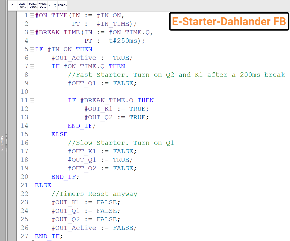
To transition from low speed to high speed, a defined switching sequence must be followed to prevent electrical stress or short-circuit conditions between winding sections. First, e-Starter Q1 is deactivated, disconnecting the supply from terminals U1, V1, and W1. After Q1 opens, a programmed pause of 500 milliseconds is implemented. This delay, stored within the control Function Block, ensures complete current decay and safe disconnection before reconfiguration occurs. Following this pause, contactor K1 closes to change the internal winding connections required for high-speed operation. Once K1 is confirmed closed, e-Starter Q2 is activated. The supply from T1, T2, and T3 of Q2 is then applied to terminals U2, V2, and W2 of the motor, establishing the high-speed pole configuration. At last, when the motor is switched off, both e-Starters and the contactor open, and all voltage from the motor terminals is removed, returning the system to its initial de-energized state.
TIA Portal Function Block: Dahlander Motor with ET 200SP E-Starters
To simplify the switching procedure for the user, a dedicated Function Block was implemented in TIA Portal. This module ensures that switching operations are not performed under load, thereby preventing mechanical wear of the contacts and electrical stress on the motor and switching devices. A minimum intermediate delay of 500 milliseconds is enforced between switching actions to guarantee safe current decay before reconfiguration of the Dahlander winding. Mutual interlocking is implemented electronically via control (enable) contacts in the main program, preventing conflicting switching states. In addition, reversal of the direction of rotation is carried out analogously to the speed changeover, with the additional phase sequence switching to invert the rotating field.
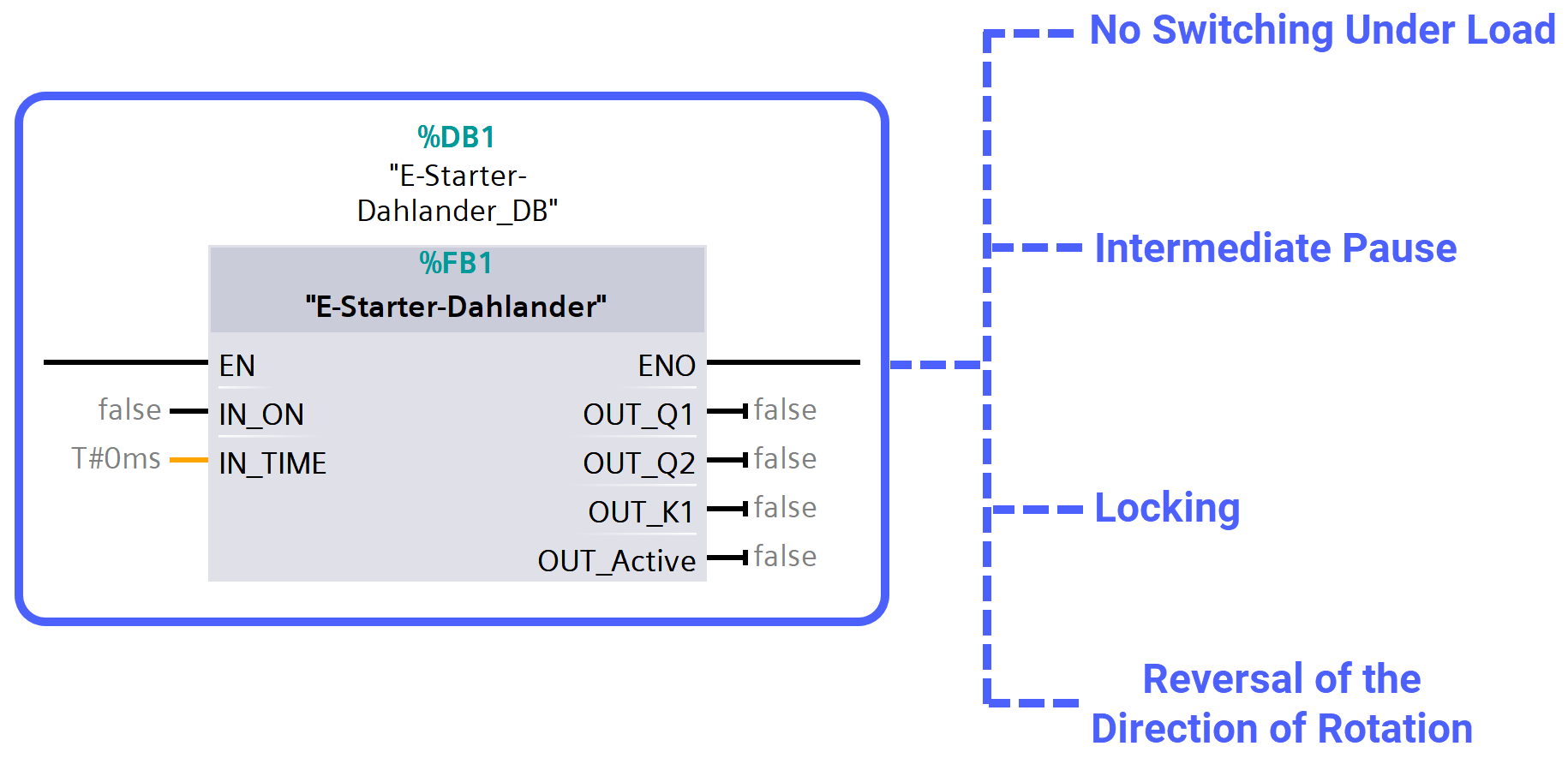
The control logic for the Dahlander motor with directional reversal is implemented in TIA Portal using a dedicated Function Block (FB).
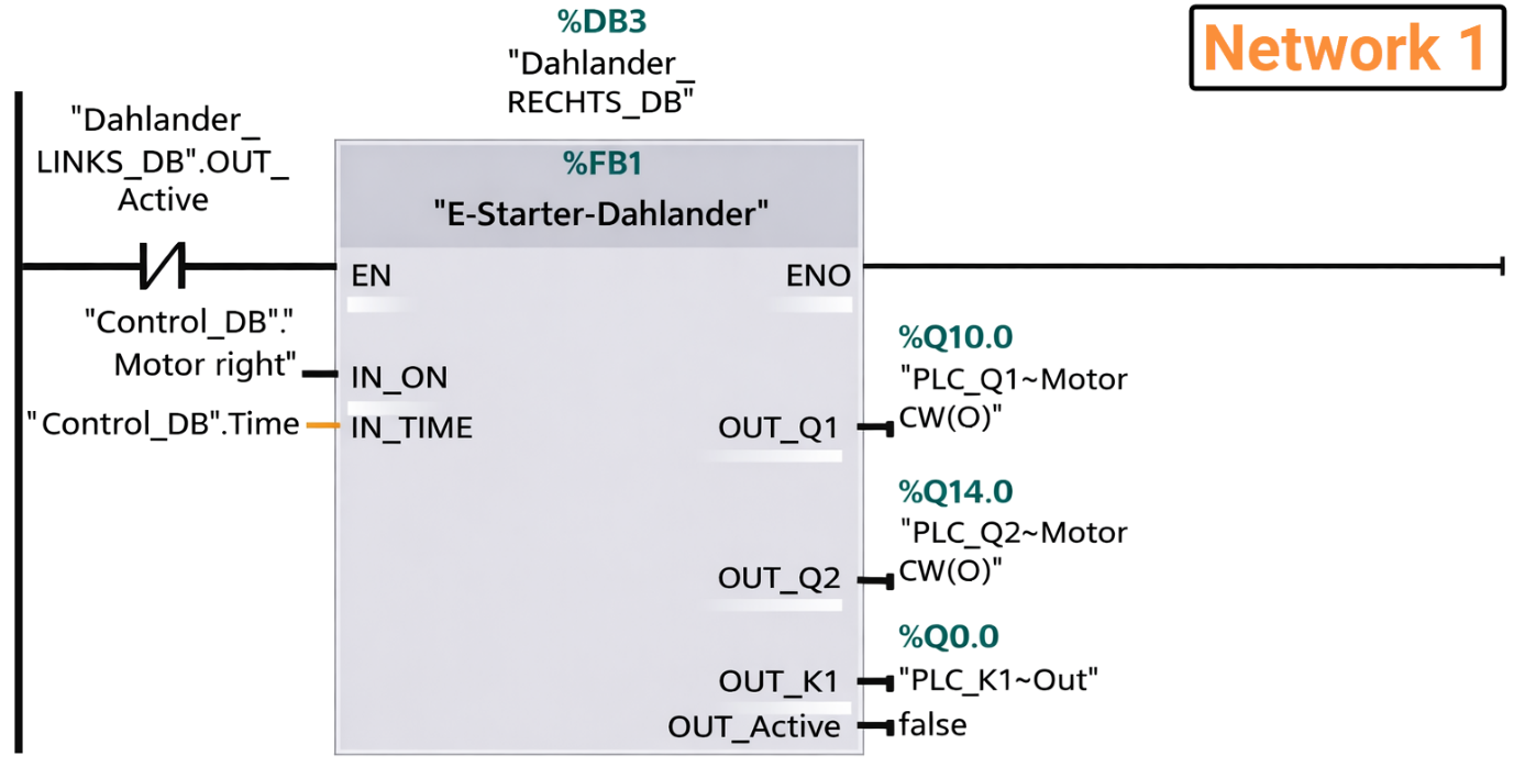
The overall control sequence is structured in the main program across three primary Networks.
Network 1 defines the control strategy for the clockwise operation of the Dahlander motor. It activates the complete switching sequence required for right-hand rotation while ensuring that left-hand rotation is not active. This directional interlock prevents opposing switching commands from being executed simultaneously. The motor is controlled through e-Starter Q1 for low-speed operation. When a change to high speed is requested, Q1 is deactivated first to guarantee load-free switching. Following an intentional pause, contactor K2, together with e-Starter Q2, is energized to configure the winding for high-speed operation.
Network 2 performs the equivalent function for counterclockwise rotation. The control logic mirrors that of Network 1 but incorporates a reversed phase sequence to invert the rotating magnetic field. The switching elements involved are e-Starters Q3 and Q4, along with contactor K3. Integrated interlocking ensures that both rotational directions cannot be enabled simultaneously.
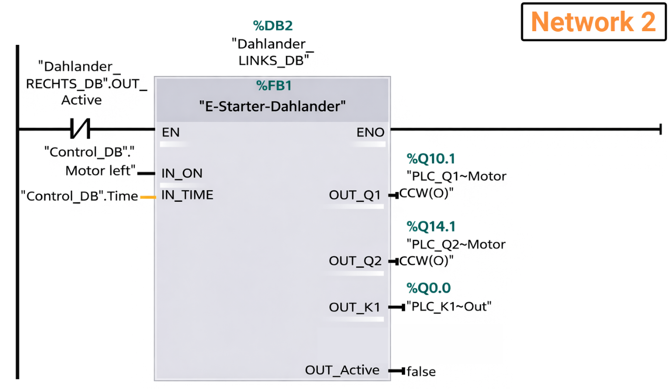
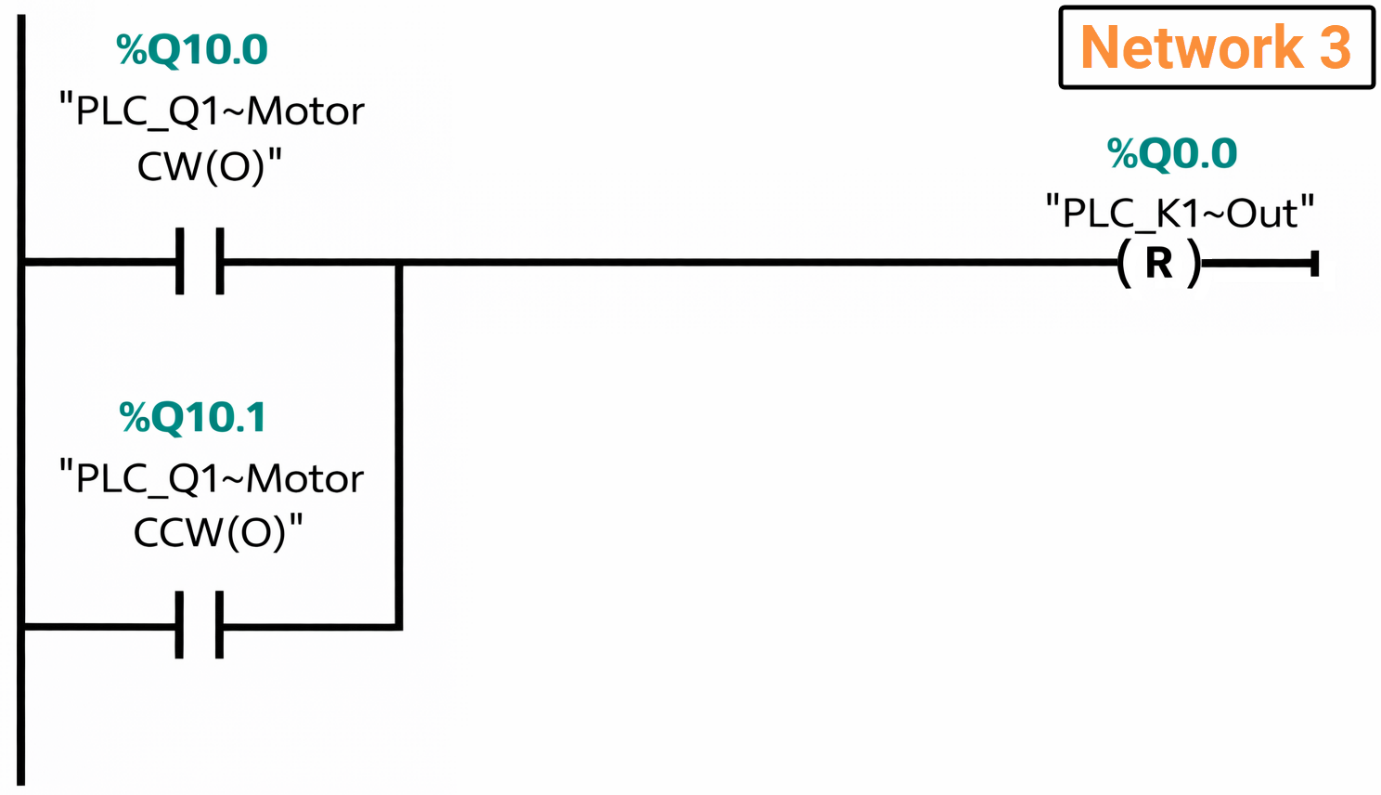
Network 3 provides additional protection against short-circuit conditions. It prevents overlapping activation of e-Starter Q1 and contactor K1, which could otherwise result in hazardous switching states. This safeguard is implemented using enable contacts and defined logical conditions within the Function Block, thereby ensuring safe pole-changing and directional transitions.
Conclusion
In conclusion, you learned how to safely and efficiently control a Dahlander motor using ET 200SP e-Starters. You now understand the difference between low-speed Delta and high-speed Star-Star configurations, how to implement safe switching sequences, and the importance of intermediate delays and interlocks to prevent mechanical or electrical damage. You also explored how to integrate this control logic into TIA Portal, including directional reversal and protection measures. By following this tutorial, you've gained practical skills that combine modern electronic starters with classic motor theory, giving you confidence to apply these techniques in real-world industrial settings.


