

How to Monitor Power Supply Status with a PLC and HMI

Introduction
Power supply failures don't announce themselves. They bring your line to a halt. That's exactly why monitoring your supply's status in real time matters. In this tutorial, you will learn how to connect the Siemens SITOP PSP6200 to an S7-1500 PLC and pull its diagnostic data straight onto an HMI screen. These parameters are voltage, current, temperature, and operating hours, all visible to your operator immediately. You will walk through every step of wiring, TIA Portal configuration, library setup, and HMI faceplate. Follow along, and you'll have a fully working monitoring setup by the time you're done.
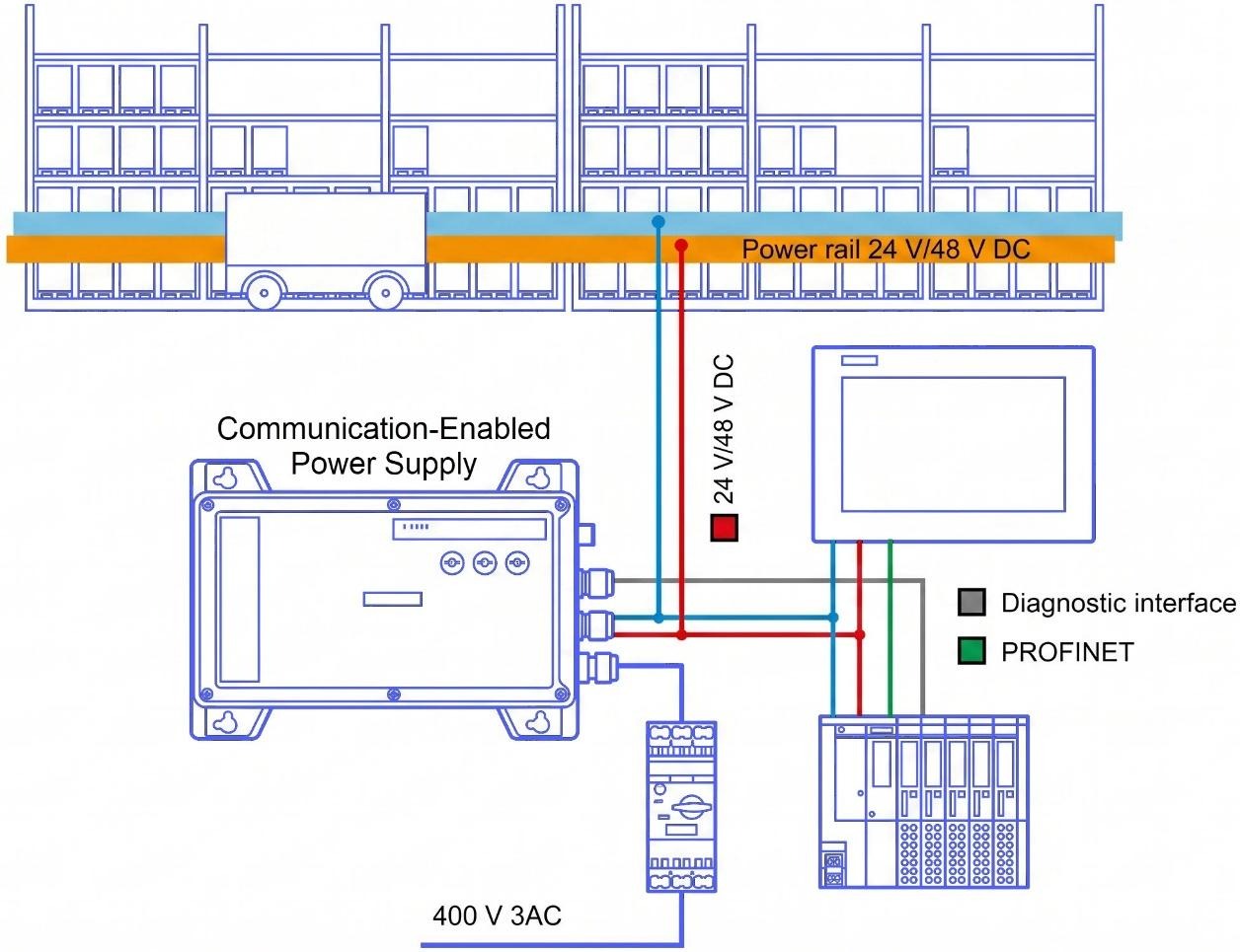
Communication-Enabled Industrial Power Supply
Communication-enabled industrial power supplies are built to be compact and tough while delivering solid efficiency, which is exactly what distributed power rail applications in modular plants demand. Included in this entry's downloadable package is a TIA Portal library that handles communication with the Siemens SITOP PSP6200, which serves here as a representative example of this type of power supply. Built around a primary-clocked switching topology, the SITOP PSP6200 is intended to be fed from a three-phase AC power supply. At the output side of the device, you get an electronically regulated DC voltage that can be adjusted to the desired level using a built-in potentiometer. The device's output is designed to be isolated and resilient to no-load and short-circuit faults. While the LED display provides an at-a-glance view of what the device is doing, the signaling contact takes things a step further by allowing the operating state to be captured and processed within a larger automation system.
Application Example Using S7-1500
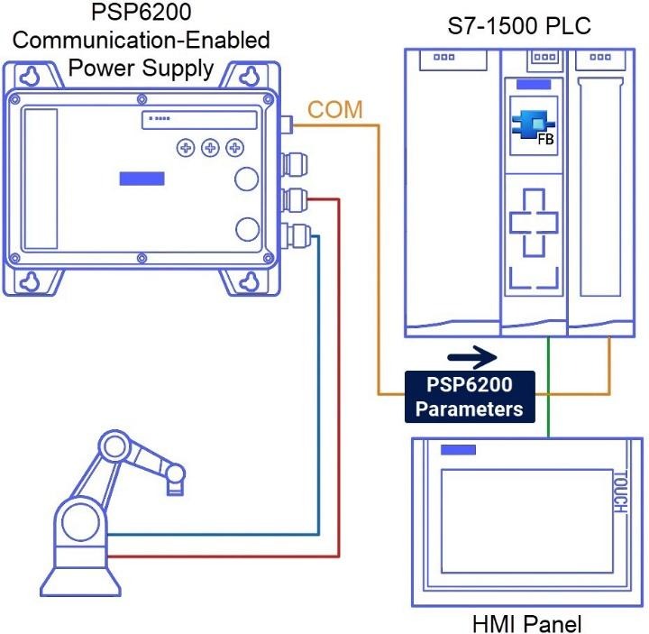
Referring to Figure 2.1, you can see the physical connection between the S7-1500 digital input module and the PSP6200. The 'COM' diagnostics interface on the PSP6200 generates a signal that bundles together various device parameters, including voltage and current levels, nominal specifications, device identification, temperature readings, and logged operating hours. On the PLC side, the S7-CPU reads the 'COM' interface signal via a digital input channel and then processes it internally. To keep things structured and accessible, the device data mentioned earlier is saved in the S7-1500 CPU under a predefined PLC data type (UDT) that acts as a consistent data container. The HMI device relies on the predefined data structure as its source for fetching and displaying the relevant device data to the operator. Reading and analyzing the 'COM' interface signal is handled by a specific Function Block called 'LPSP6200_SignalEvaluationS71500,' which tracks its behavior over time, and writes the resulting data in the right place.
Hardware & Software Configuration
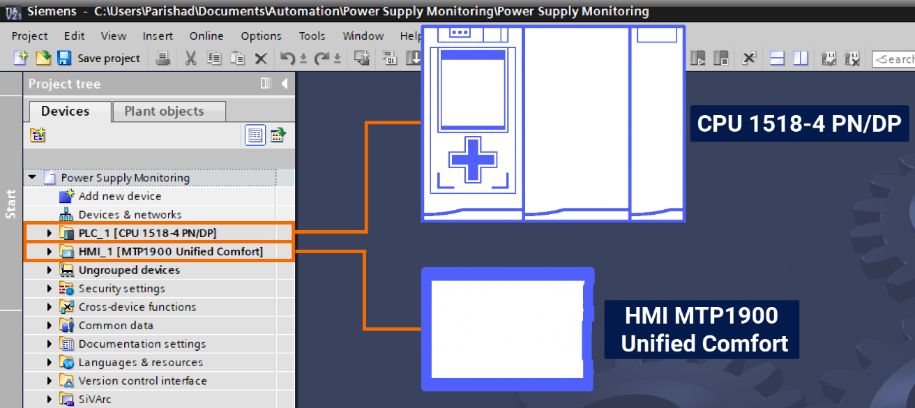
Launch the TIA Portal software on your computer. Go ahead and start a brand-new project, giving it whatever name you prefer. With your project ready, it's time to add both the PLC and HMI devices you intend to use. To follow along with this example specifically, the CPU 1518-4 PN/DP will serve as the PLC, while the MTP1900 Unified Comfort will be used as the HMI.
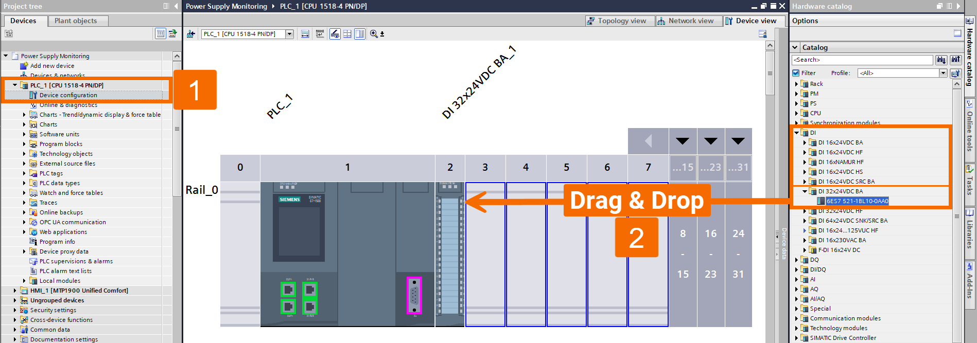
Find the PLC_1 folder in the project tree, and expand it. Then double-click on Device Configuration. Once you're in there, you can freely add any module you want, such as the DI 32x24VDC BA (digital input), to your PLC.
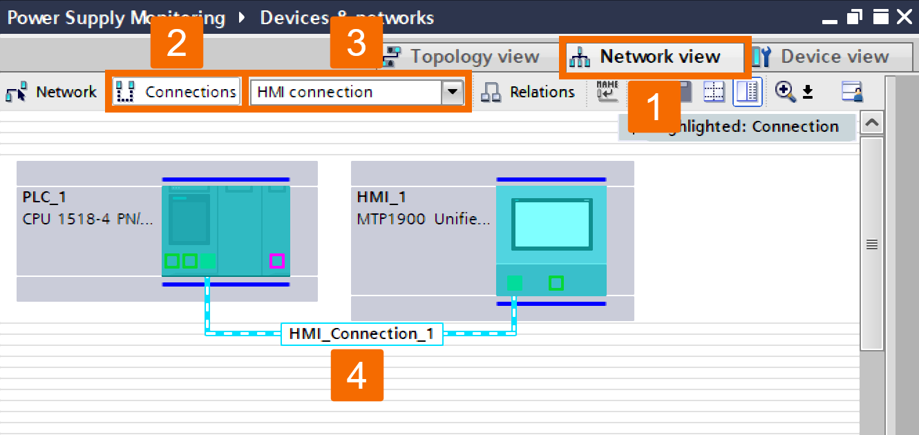
Switch to the Network View tab, then look for the Connections icon up in the toolbar and click it. Doing so will put you into connection mode. From the drop-down list sitting to the right of the Connections icon, make sure you pick HMI Connection as your connection type. On the device you're starting from, click its subnet interface. While holding the mouse button, slowly move the mouse pointer toward the interface on the target device. Once you're lined up, release the mouse button.
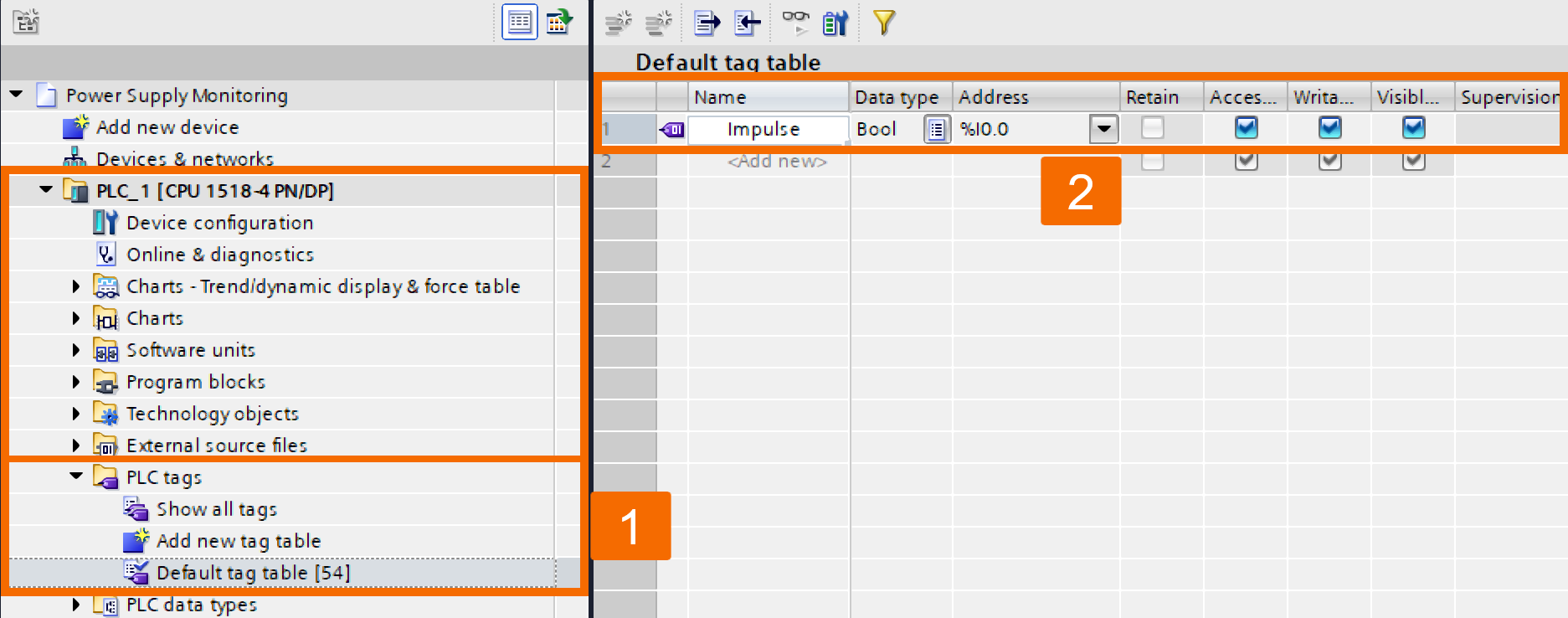
Head into the PLC Tags folder and double-click the Default Tag Table to open it. The tag table will then load for you to start editing. Locate the Address column in the tag table and type in the address of the digital input you're using to read in the COM diagnostics interface. Set the data type to Bool in the Data type column, and then move to the Name column, where you can assign any name you want to your PLC variable.
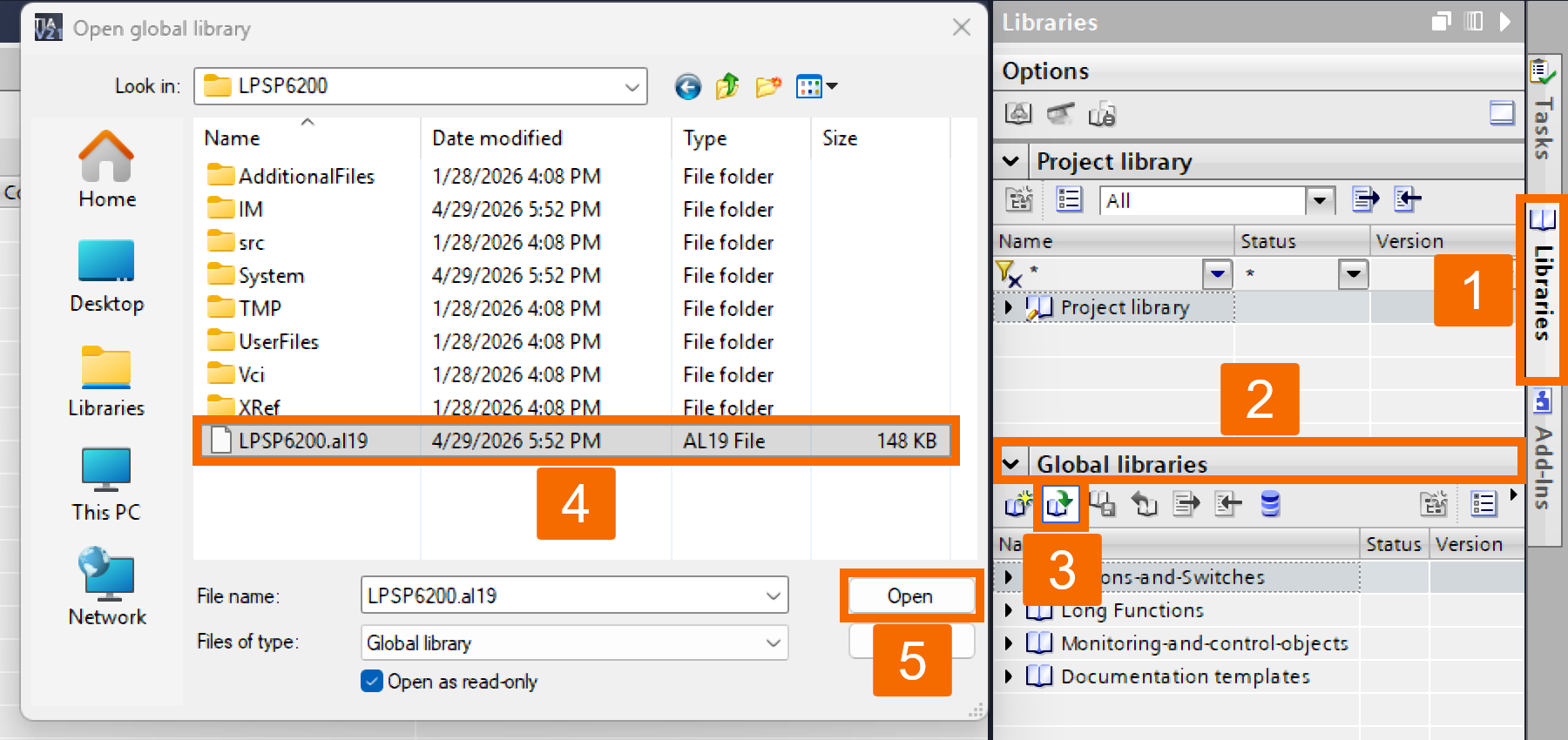
At this point, it's important to ensure the LPSP6200 library has already been downloaded from the link here and extracted to a location of your choice on your computer. Click the Libraries task card to open its section, and then open the Global Libraries palette. Once you're there, use the Open Global Library button to open the library. As soon as the dialog box opens, select the appropriate library. Once you've made your choice, confirm it by clicking Open.
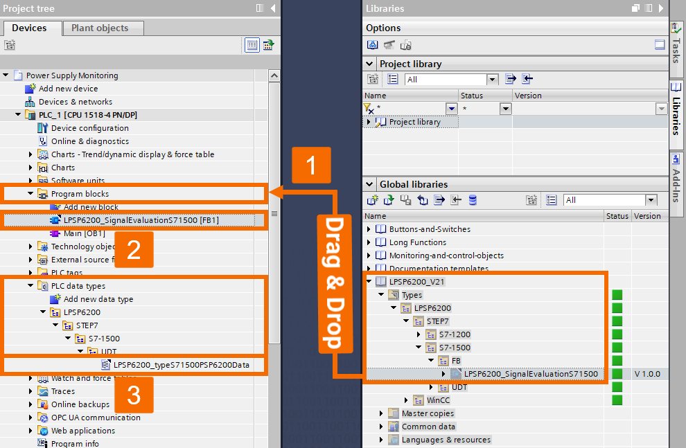
Using the drag and drop method to take the Function Block that matches your S7-CPU and place it into the Program Blocks folder of your target device, such as an S7-1500 CPU. This Function Block brings along its own user-defined PLC data type. So, whenever you integrate the Function Block into your project, that data type is automatically placed in the PLC Data Types folder of your PLC without any extra steps.
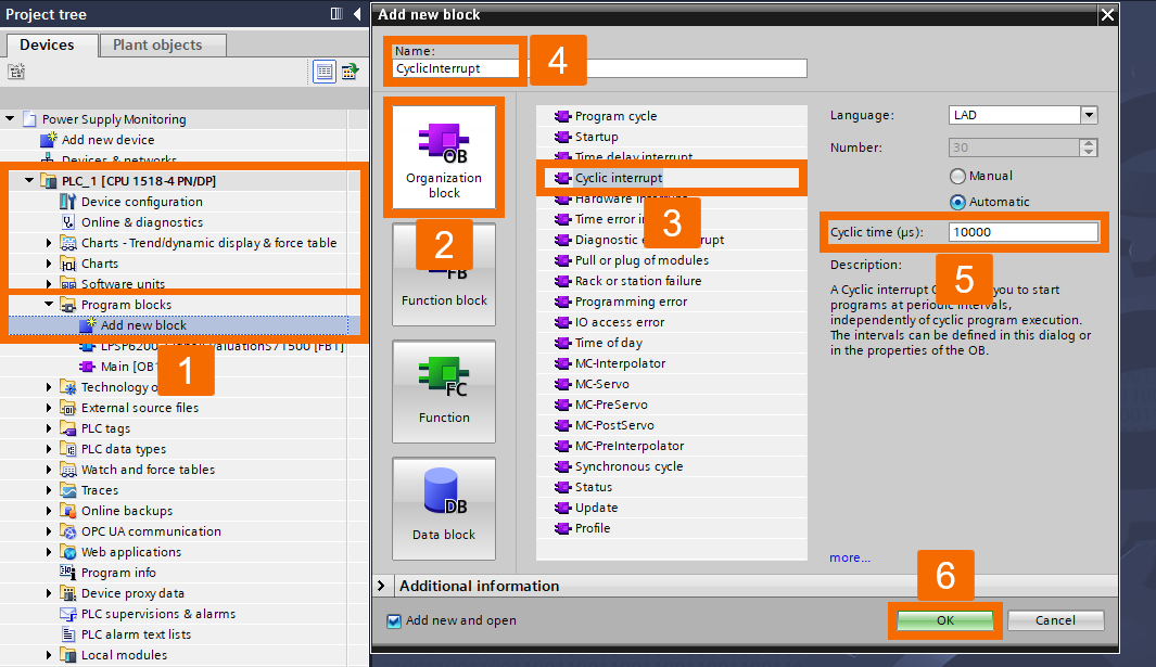
Head into the Program Blocks folder and double-click Add New Block to kick off the process of adding a cyclic interrupt OB to your program. Once the Add New Block dialog opens, select the Organization Block icon and then pick Cyclic Interrupt as the block type to create your cyclic interrupt OB. You'll also need to enter the cycle time, specified in microseconds (µs). Just make sure it stays under 10 ms, as exceeding it could affect how the FBs are called.
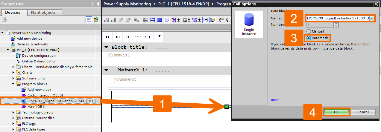
Pull the LPSP6200 Function Block out of the project tree by using drag and drop, and place it into Network 1 within the cyclic interrupt OB. Right after that, the Call Options dialog will pop up automatically. Type in your preferred name for the instance DB, and ensure to select the Automatic radio button so the DB number gets assigned automatically by TIA Portal. Once that's set, click OK to wrap things up.
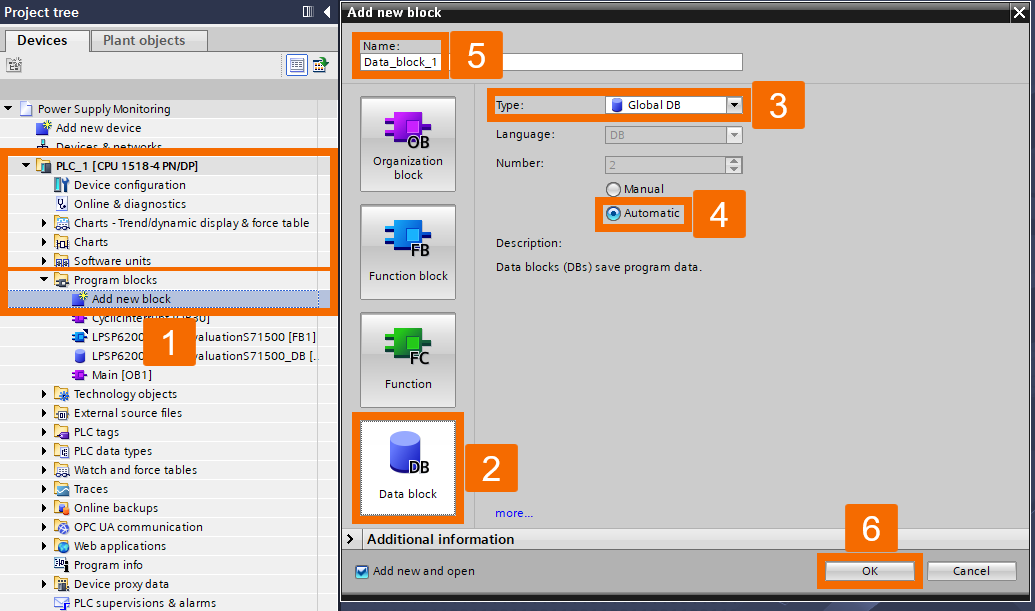
In the next step, you will learn how to set up a global data block that handles data exchange. The whole purpose of this data block is to store data retrieved from the SITOP PSP6200 power supply using the LPSP6200 Function. To start adding a new data block, double-click the Add New Block item. When the dialog opens, select the Data Block symbol. Then choose Global DB as the block type. Insert a name for the DB, and confirm your settings by pressing OK.
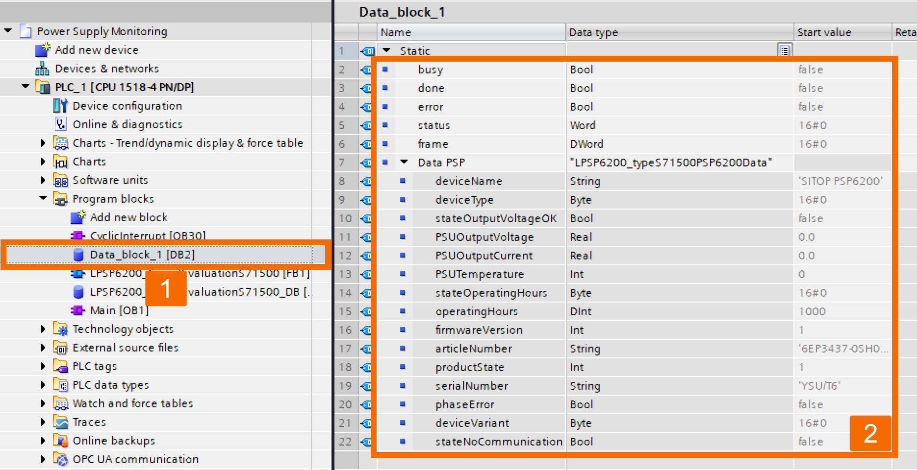
The moment the newly created global data block appears in the work area, double-click <Add new> and start defining the variables according to what's shown in the guide.
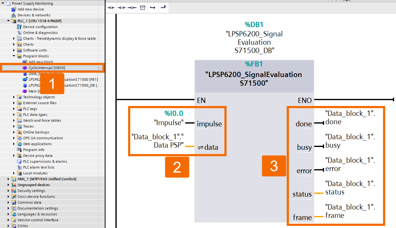
To open the program editor for the cyclic interrupt OB, go ahead and double-click on it in the project tree. Take the PLC variable that corresponds to the address of the digital input through which the COM diagnostics interface is read in, and assign it to the Impulse input. Take the PLC variable that corresponds to the address of the digital input through which the COM diagnostics interface is read in, and assign it to the Impulse input. Link the variables you've already defined in the global data block to the output parameters of the Function Block to complete the assignment.
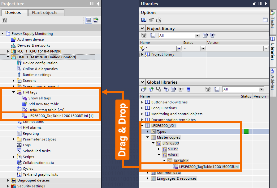
Expand the HMI_1 node in the project tree by clicking the arrow next to it, and then look for the HMI Tags folder inside. Inside the LPSP6200 library, the tag table you're looking for can be found by navigating through the directory Master Copies → LPSP6200 → WinCC → TagTable. The LPSP6200 tag table needs to be dragged from the library and dropped into the HMI Tags folder of your HMI operating panel.
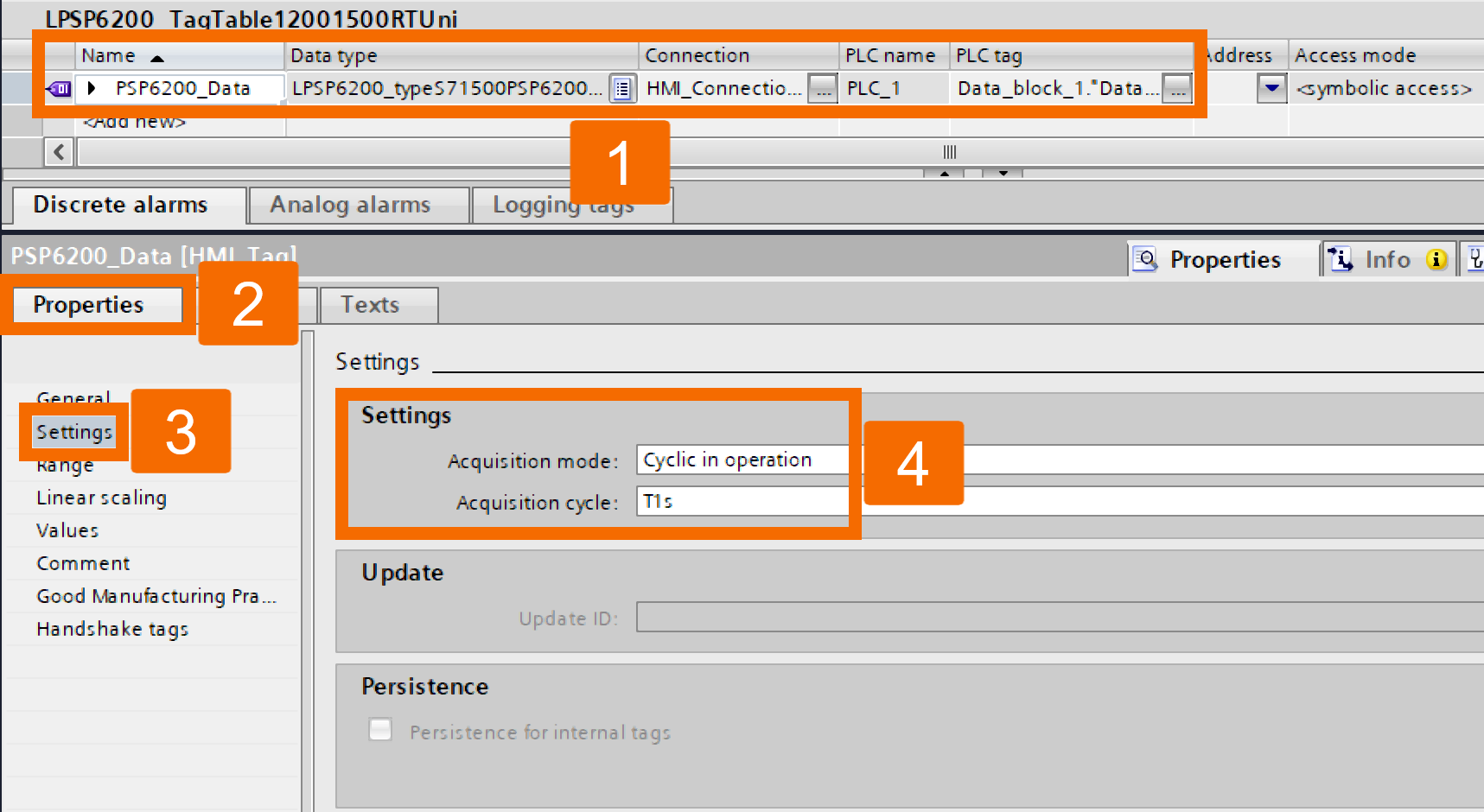
Open the tag table and carefully verify that the Data Type, Connection, PLC name, and PLC Tag settings exactly match those shown in the configuration example. From the tag table, click on PSP6200_Data to select it. Once you do, the Inspector window will load and show you all of this variable's properties. Open the General tab and navigate your way to Settings. Once you're there, choose Cyclic Continuous as the Acquisition mode and select 1 second for the Acquisition Cycle.
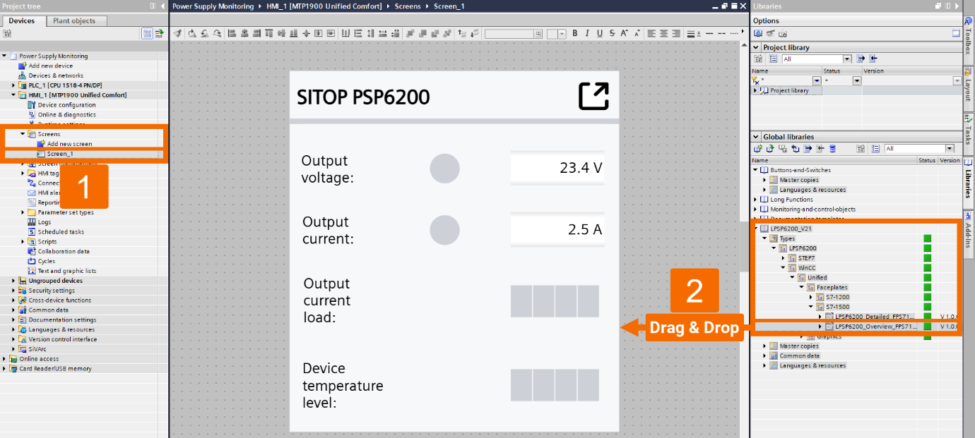
Find the screen where you'd like to add the faceplate to display the SITOP PSP6200 device data. Double-click it to open it up in the screen editor. Open the folder path Types → LPSP6200 → WinCC → Unified → Faceplates inside the library, where you'll find the faceplates available for S7-1500 CPUs. Go ahead and drag an instance of the Overview faceplate and then drop it onto the screen you have open.
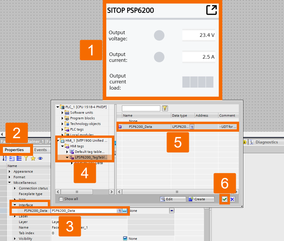
Click on the faceplate in the screen to select it, then open the Properties tab and navigate to the Interface section. From there, find the property 'DataPSP6200' under the 'Data' category and connect it to the HMI tag you created earlier.
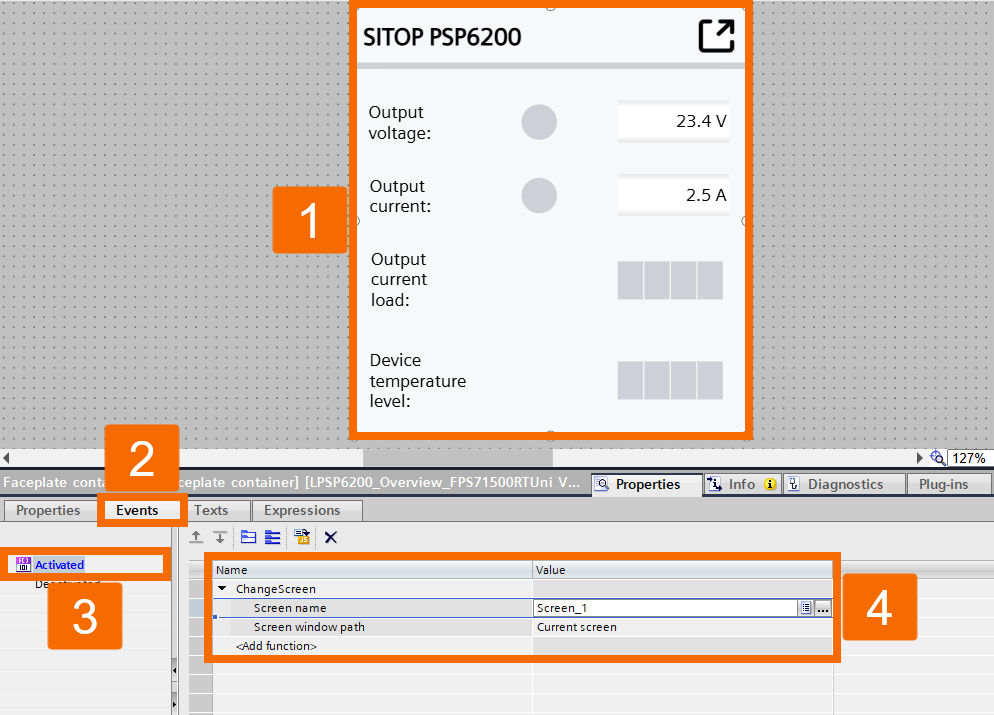
Opening the Detailed faceplate occurs when you click the Overview faceplate. Should you want to configure this yourself, click on the faceplate, navigate to Properties → Events, and left-click Activated. From the drop-down list, select ChangeScreen, and then go ahead and add the Screen Window Path and Screen Name.
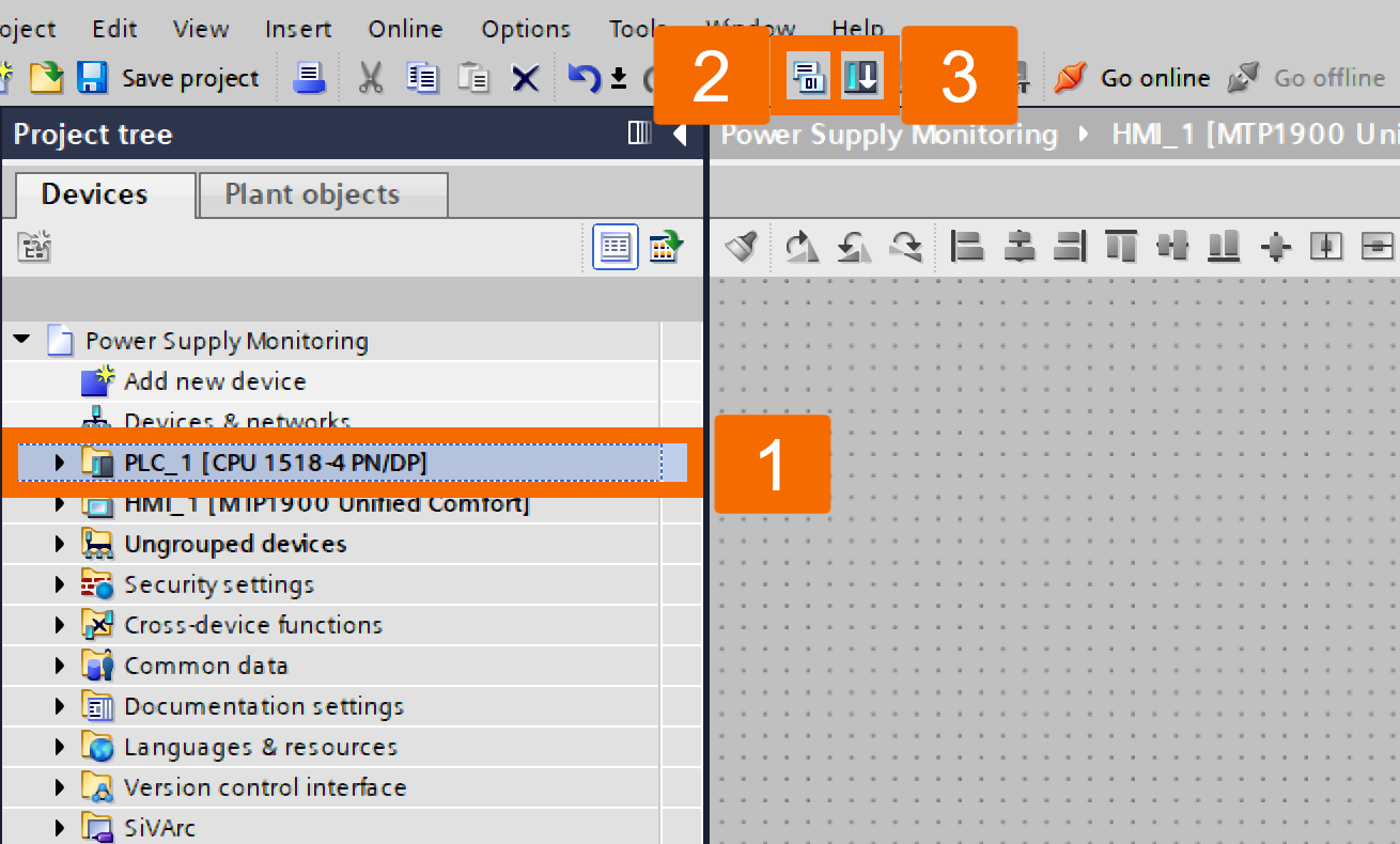
In the project tree, click on the PLC folder to select it, then use the Compile button in the toolbar to compile everything. Follow that up by clicking Download to device in the toolbar to transfer the hardware configuration and software to the CPU.
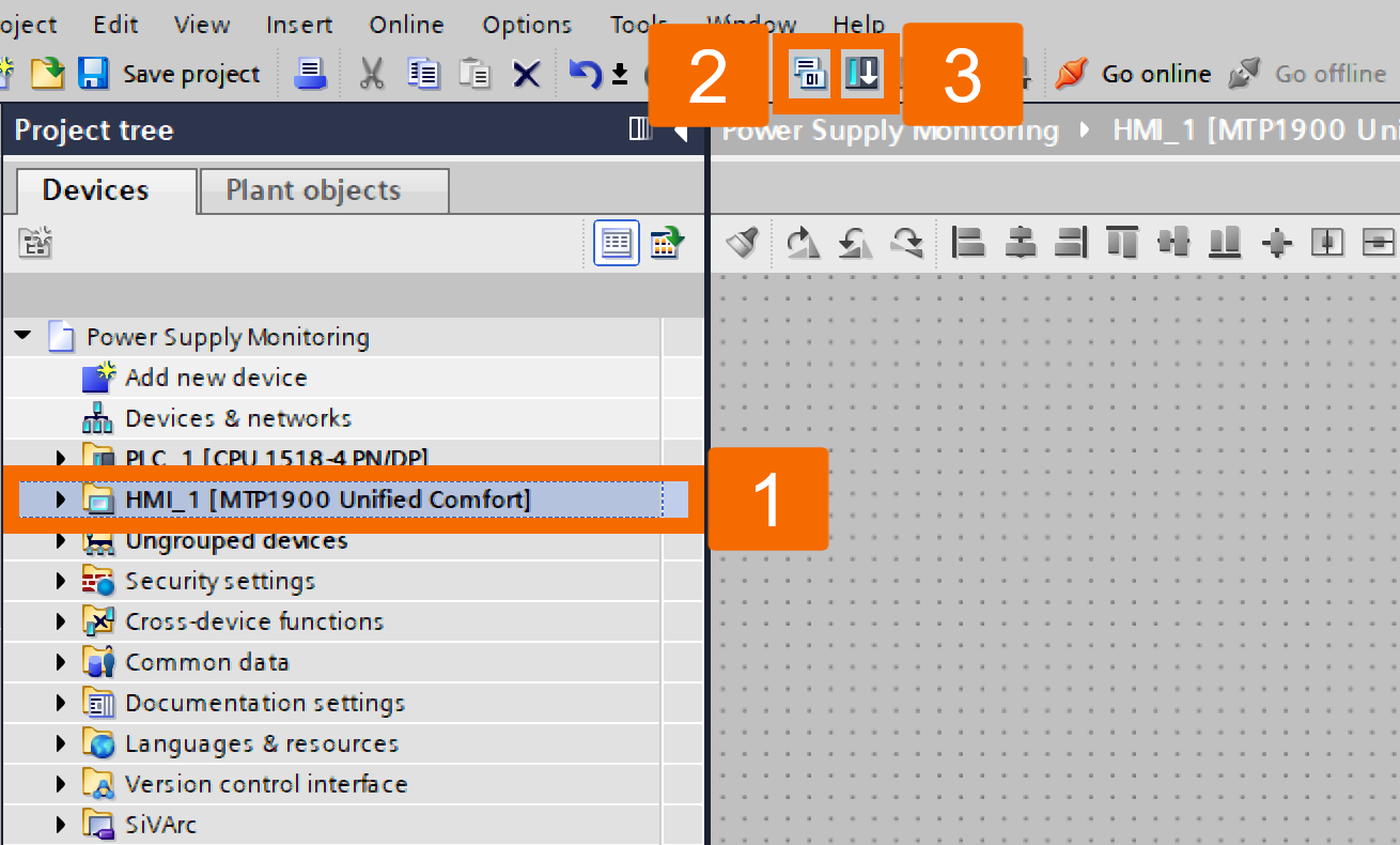
Go through the same procedure for the HMI device as well. Once finished, choose the HMI operating device from the project tree and left-click on the Start Simulation button up in the toolbar.
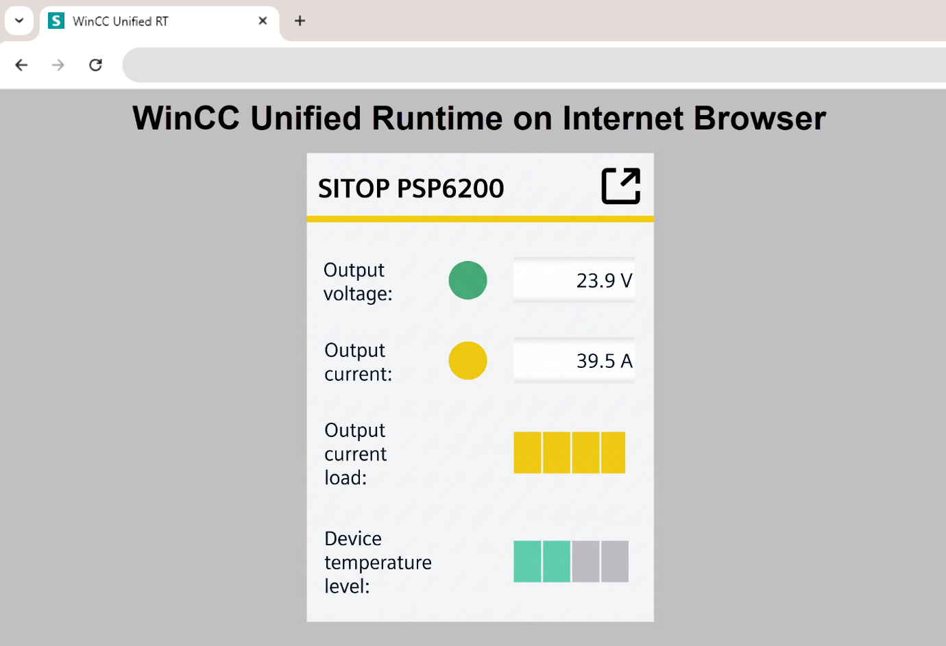
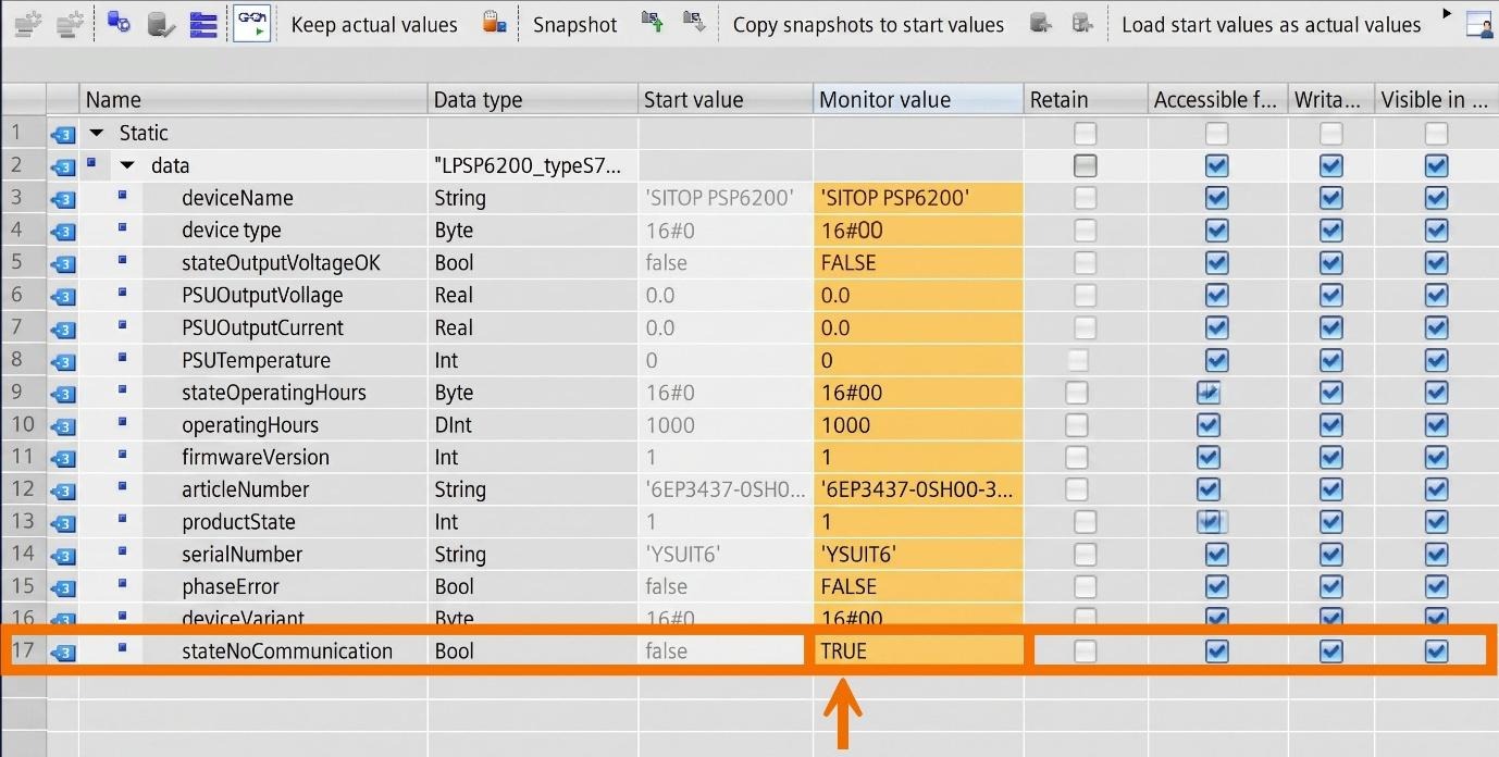
If you notice the faceplate shows default values instead of actual device data, that is a sign there's a communication issue between the HMI device and the PLC. In that case, open the data block and check whether 'StateNoCommunication' is set to True.
Conclusion
In conclusion, you have learned how to take a piece of hardware that most people treat as a black box and wire it into your automation system in a meaningful way. You now know how to read the power supply's COM diagnostics interface through an S7-1500 digital input, set up the corresponding Function Block properly, structure your data so the HMI can reach it cleanly, and get a live faceplate in front of your operator. It's a straightforward setup once you've done it, and it saves you a lot of guesswork the next time something on your power rail starts behaving unexpectedly.


