

How to Read and Write RFID Tags in Siemens TIA Portal

Introduction
Working with RFID in an industrial setting can feel intimidating the first time you open TIA Portal and stare at an empty project. This tutorial walks you through the entire process, from configuring the RF188C communication module and the PROFINET network to integrating the LIDENT library and wiring up Auto and Manual function blocks. You'll learn how automatic and user-controlled command execution differ, how to parameterize readers and transponders, and how to read and write tag data with confidence. By the end, you'll have a working, tested application and a much clearer picture of how PROFINET-based identification systems operate.
Application Example Overview
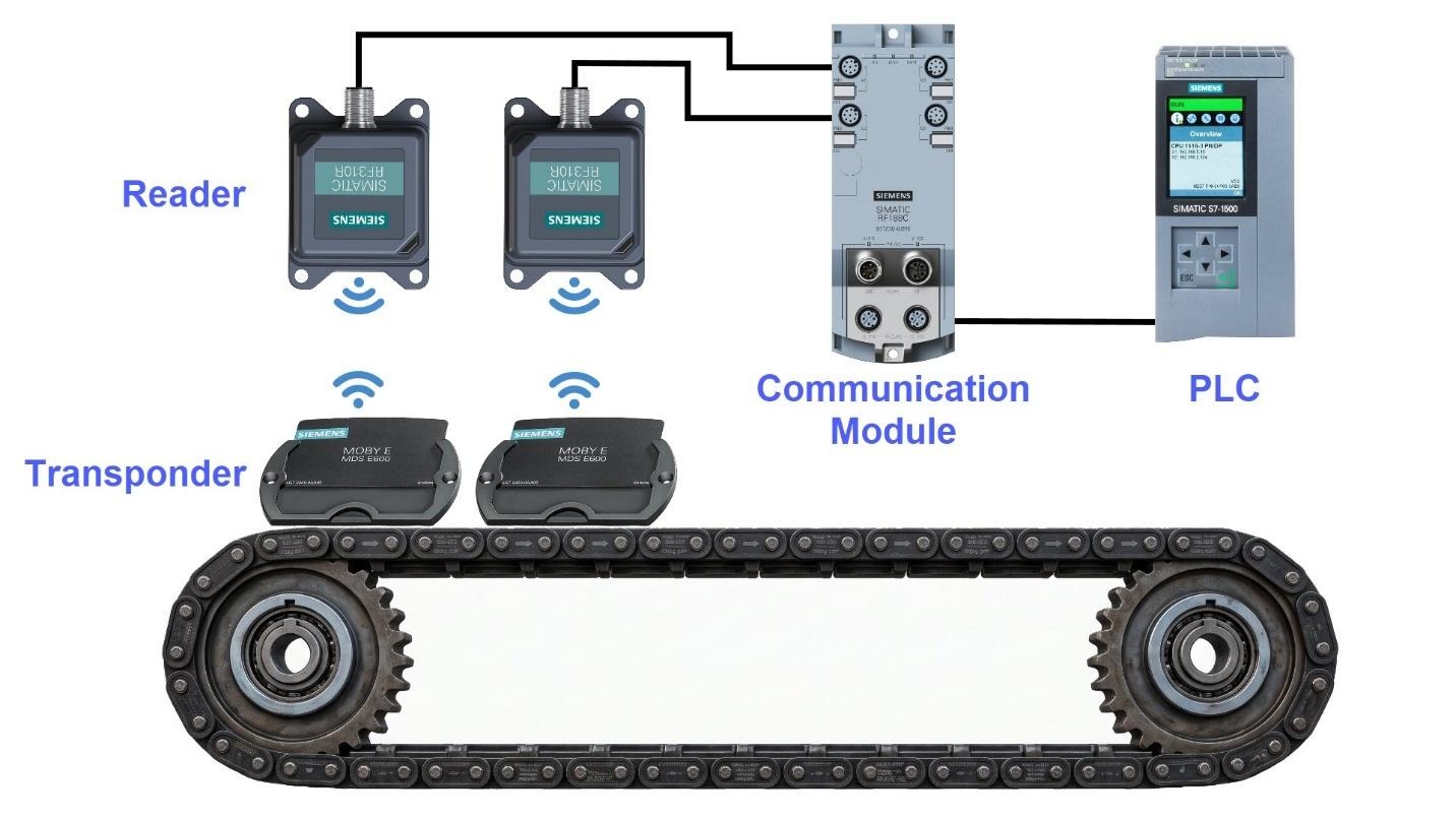
A dedicated library named 'LIDENT' supplies function blocks that let you control compatible industrial identification modules over cyclic PROFINET I/O communication. There are two operating modes available within the cyclic PROFINET I/O protocol. First is the automatic command execution. This operating mode runs the control automatically, so there's no need to start it manually from the user program. The second operating mode is user-controlled command execution. Here, you can use the user program to key the desired command to trigger it manually.
General Hardware Configuration
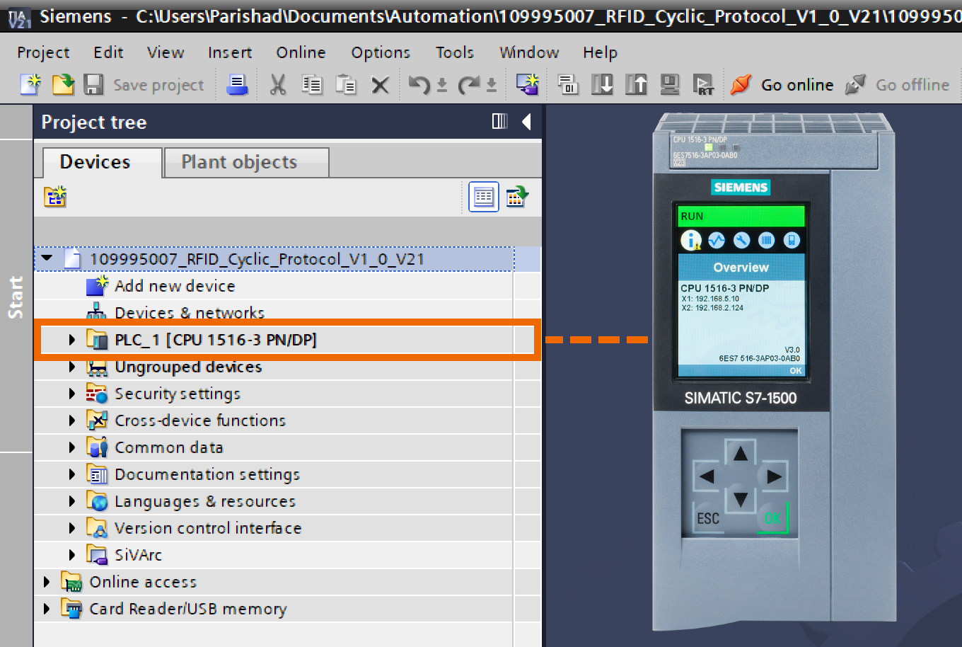
Once TIA Portal is open, create a new project and select the 1516-3 PN/DP as your CPU.
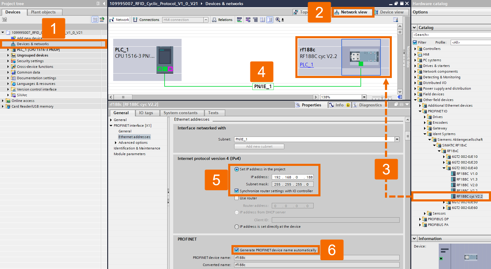
Double-click Devices & Networks afterward to bring up its window, then switch to Network View. Cyclic PROFINET communication runs through the 'RF188C cycle version 2.2' object, which you can insert into the hardware configuration by double-clicking it. Draw a network connection between your PLC and the communication module to establish the link between the CPU 1516-3 PN/DP and RF188C. Configure the communication module's IP address and PROFINET name to allow proper communication between the devices.
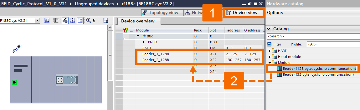
Double-click the RF188C object to open the Device View for the communication module. From the Hardware Catalog, pick the reader object you plan to configure and assign it to the communication module's corresponding port. Two options exist here, depending on the data length required for cyclic I/O communication. First is the '128 Bytes Cycle' reader, suited for applications handling larger data volumes for each cycle. Second is the '32 Bytes Cycle' reader, useful for applications needing less data or aiming to lighten bus load. In this application example, configure the 128-byte reader variant across slots X21 and X22.
Function Blocks Integration
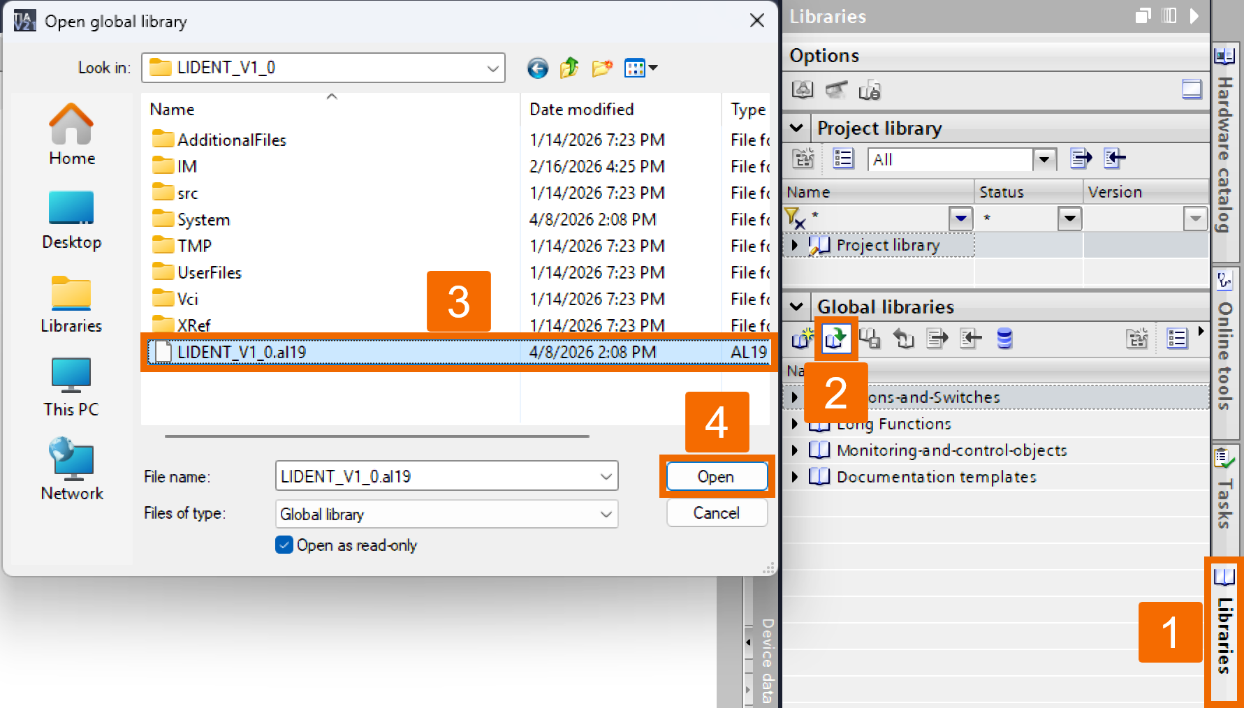
Go to the right-hand Libraries tab in TIA Portal. Then, under the Global Libraries section, open the LIDENT library you grabbed from this link.
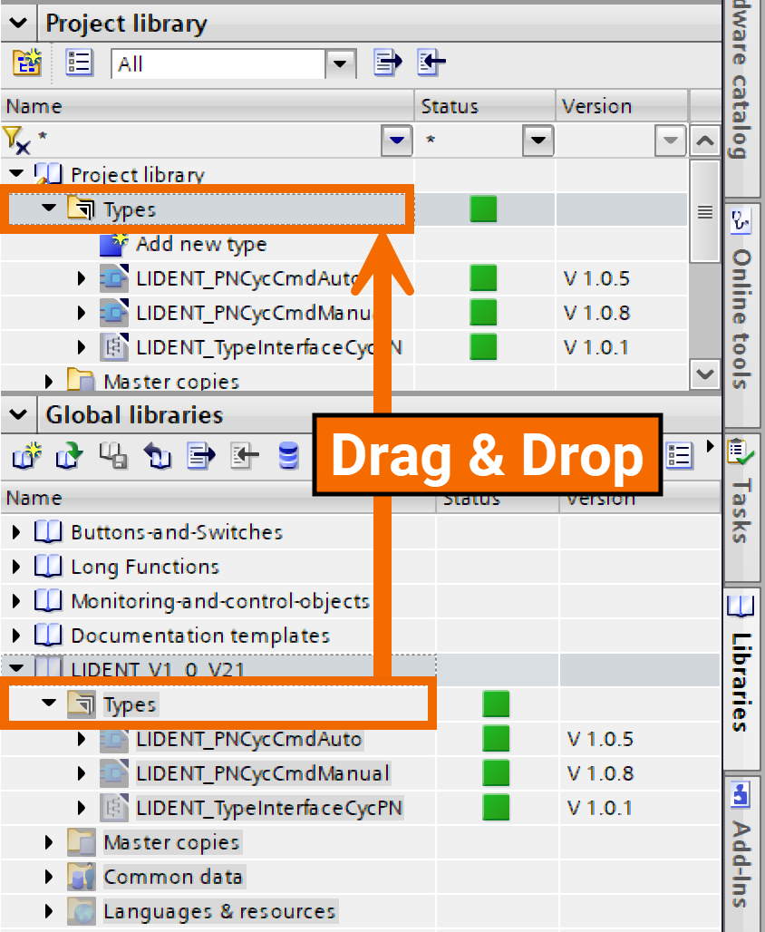
From the library opened in the lower pane, drag its Types folder over and drop it onto the Project Library's Types folder. Using the LIDENT_PNCycCmdAuto block, the command's result comes back on every cycle, but issuing the command in the first place is only possible via hardware configuration. The LIDENT_PNCycCmdManual block lets you manually set a command right in the user program. Even though the block's input parameters handle this command, you'll still need to adjust the reader's hardware configuration.
Special Hardware Configuration
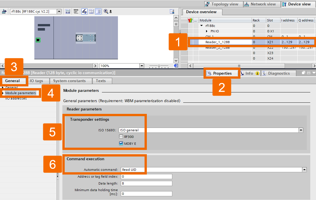
Choose the configured reader to set up its transponder settings first. From there, decide which transponder type your reader should talk to. In this example, 'Reader_1_128B' is used and paired with the LIDENT_PNCycCmdAuto function block. Since you'll be reading a tag's UID going forward, the settings were parameterized accordingly, as shown.
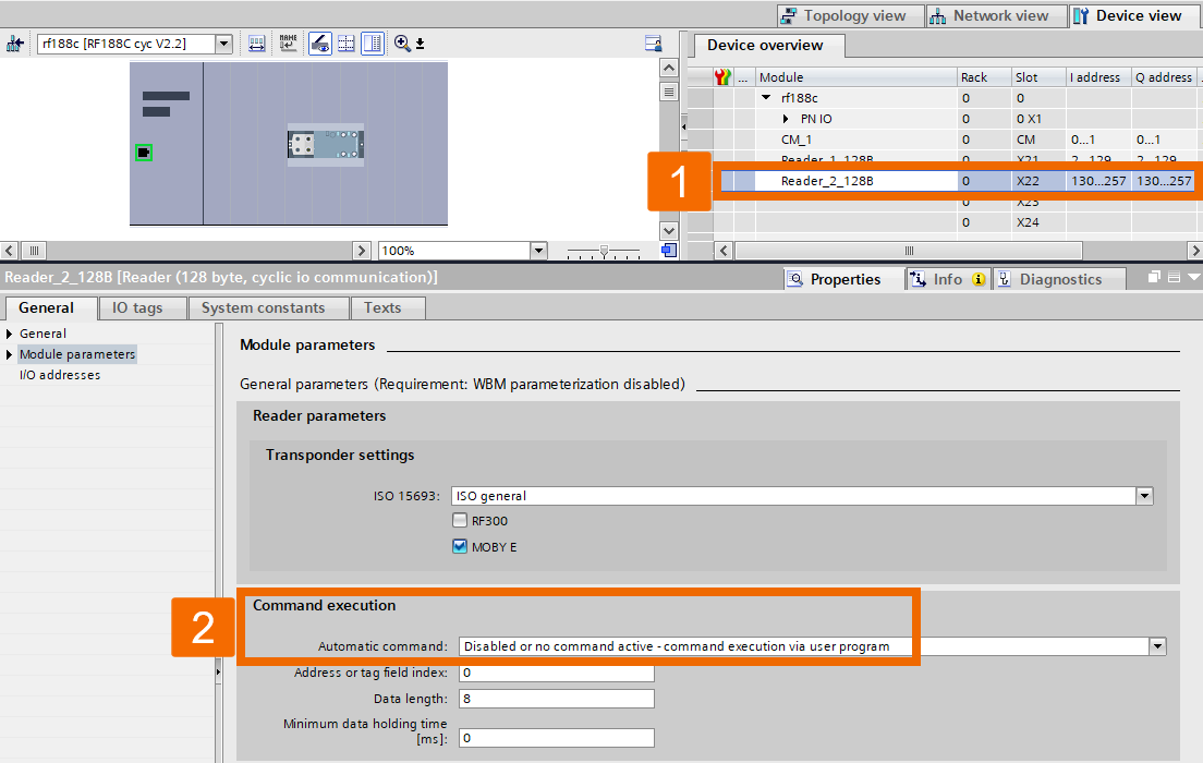
If LIDENT_PNCycCmdManual block is what you're after, make sure automatic command execution is disabled. Here, 'Reader_2_128B' serves this exact purpose.
Function Block Calling
From the Project Library, pick the block that matches the reader you just configured in the hardware configuration, then drag it into the Program Blocks folder. Open the Organizational Block meant to process the program by double-clicking it; here, it's OB1.
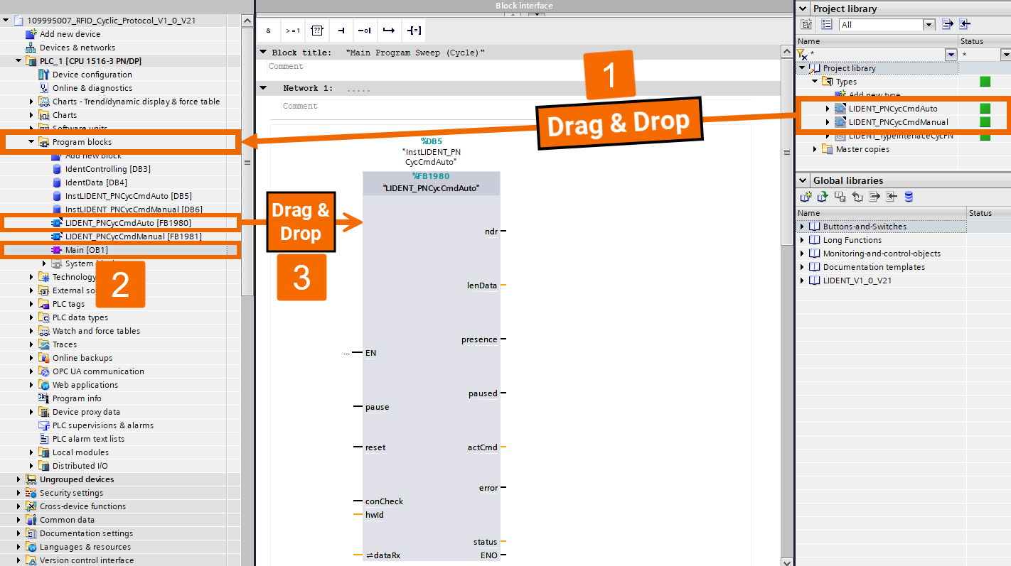
Drag the function blocks from the Program Blocks folder into networks in OB1 to create their instances.
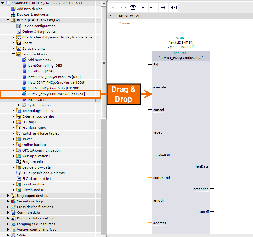
Data Blocks Creation
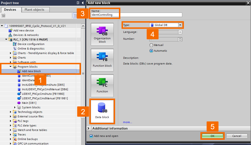
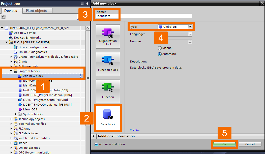
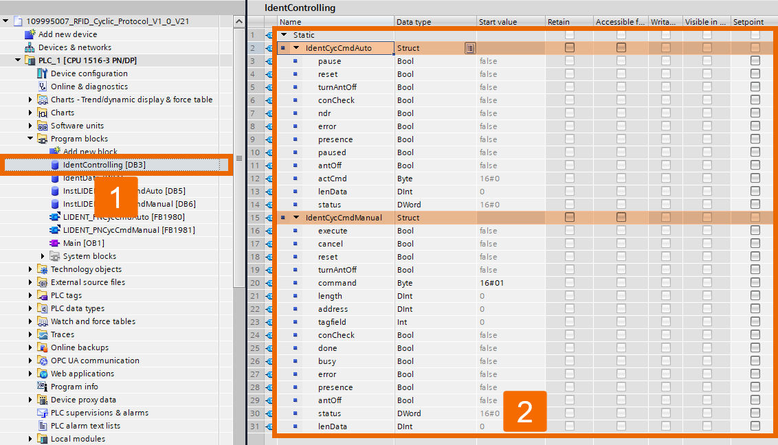
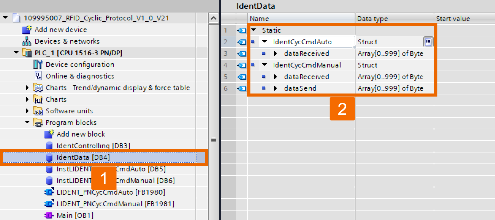
The device parameters go into the data module, IdentControlling, while send/receive buffers go into IdentData. You need to build two data blocks individually. For the first data block, double-click Add New Block under the Program Blocks folder. When the dialog opens, select the Data Block tab on the left and type in the first module's name.
Do the same for creating the second data block.
Add two Struct variables to the IdentControlling block, labeling them IdentCycCmdAuto and IdentCycCmdManual. Next, set up all the input and output variables with the right data types.
The data module IdentData serves as the buffer, either input or output. It starts with creating two Struct variables.
Data Blocks Interconnection with Function Blocks
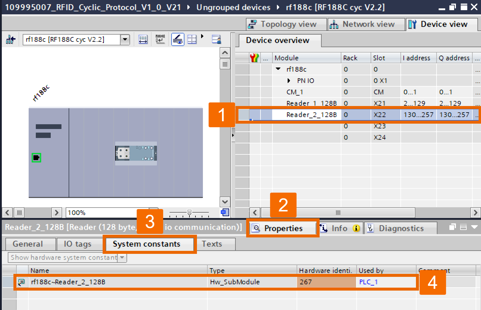
Double-click on the communication module within Devices & Networks to switch to Device View. Select 'Reader_1_128B' since it'll interconnect with the Auto function block. Switch to System Constants within the Settings tab and record the hardware identifier there.
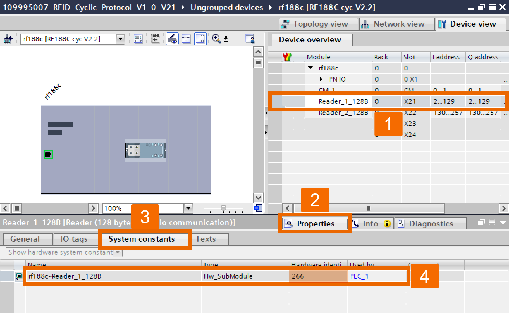
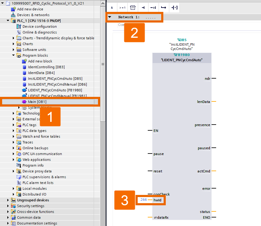
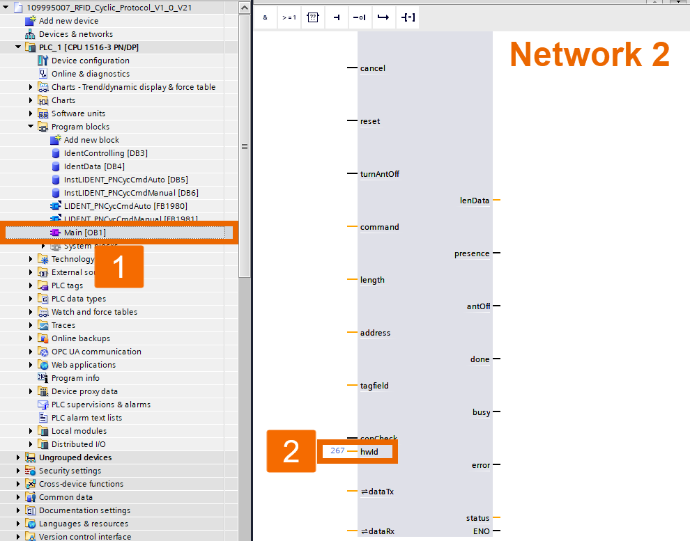
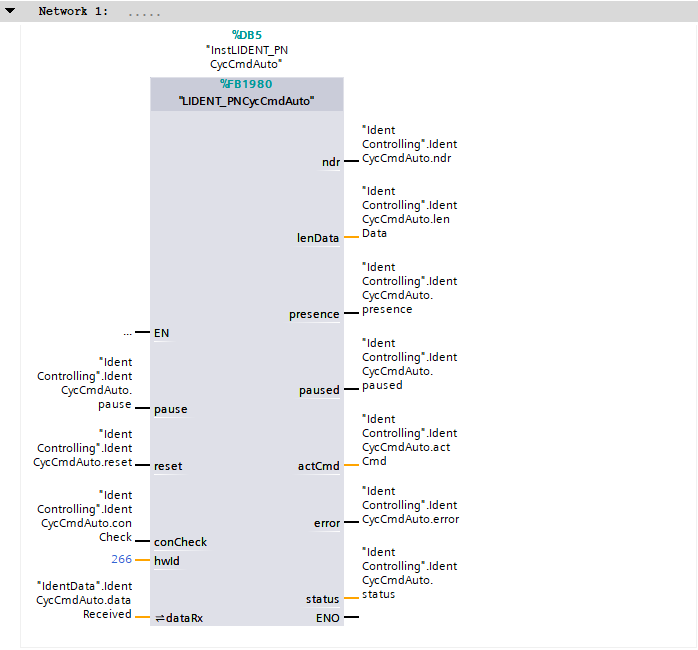
Head to OB1 and, at the Auto FB's 'hwId' input in Network 1, enter the hardware ID you determined in the previous step.
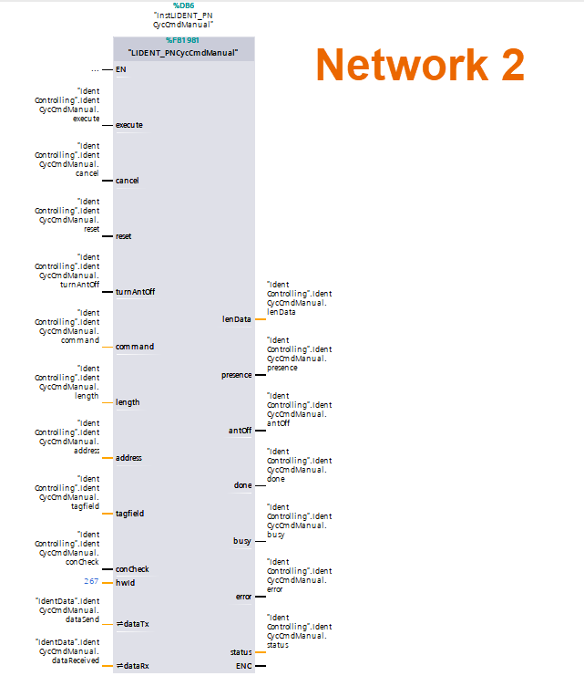
Next, redo these steps for 'Reader_2_128B', getting its hardware ID from the communication module so it can be linked to the Manual FB's 'hwId' input within Network 2 of OB1.
For the remaining variables, you could connect them to the appropriate inputs or outputs through direct text entry for both networks.
Auto Function Block Operation
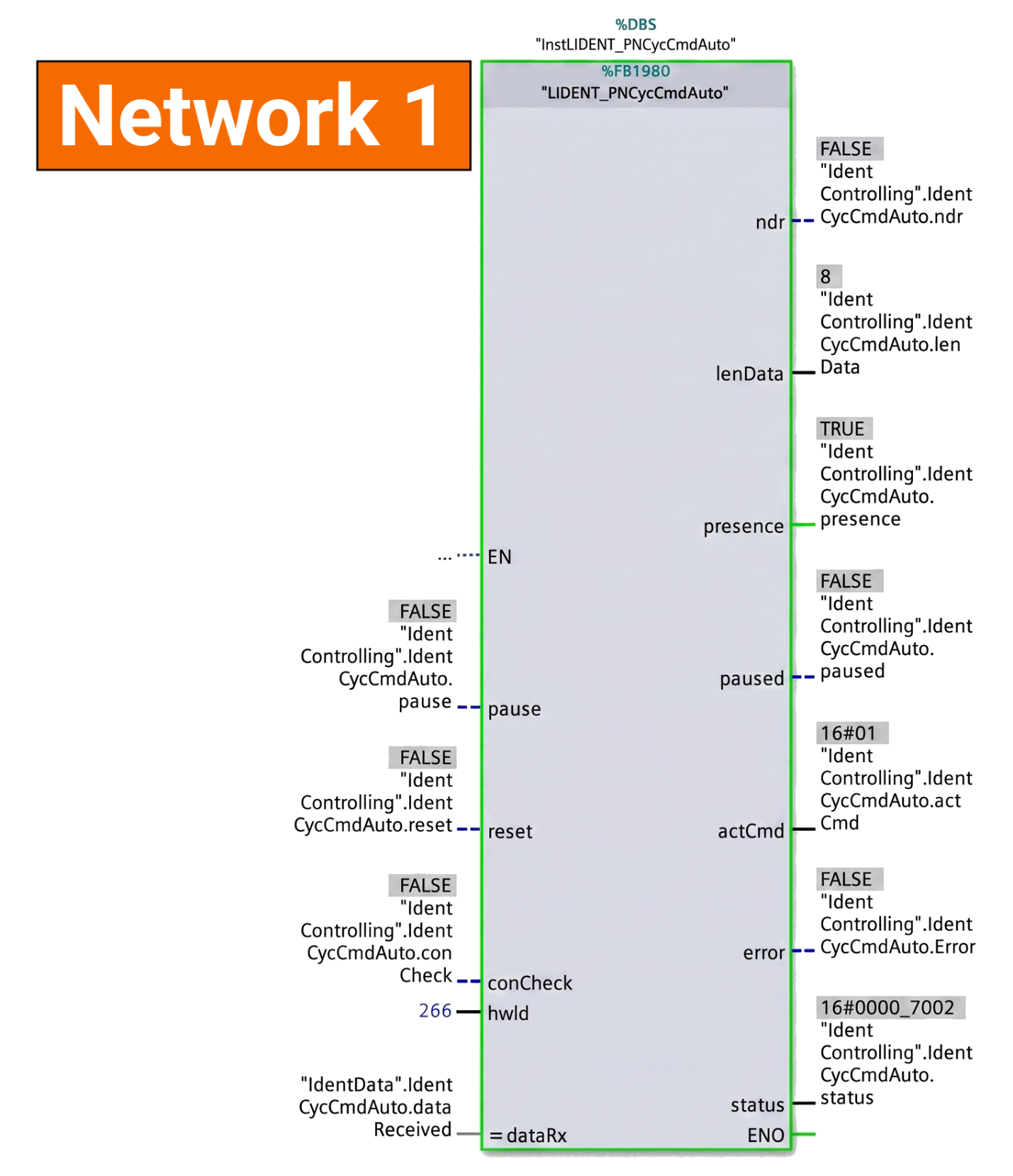
Compile the program, download it to the PLC, then open the online view in OB1. Using the Auto FB, the transponder's UID gets read automatically as soon as the reader detects it. The parameters listed below then appear after a successful run.
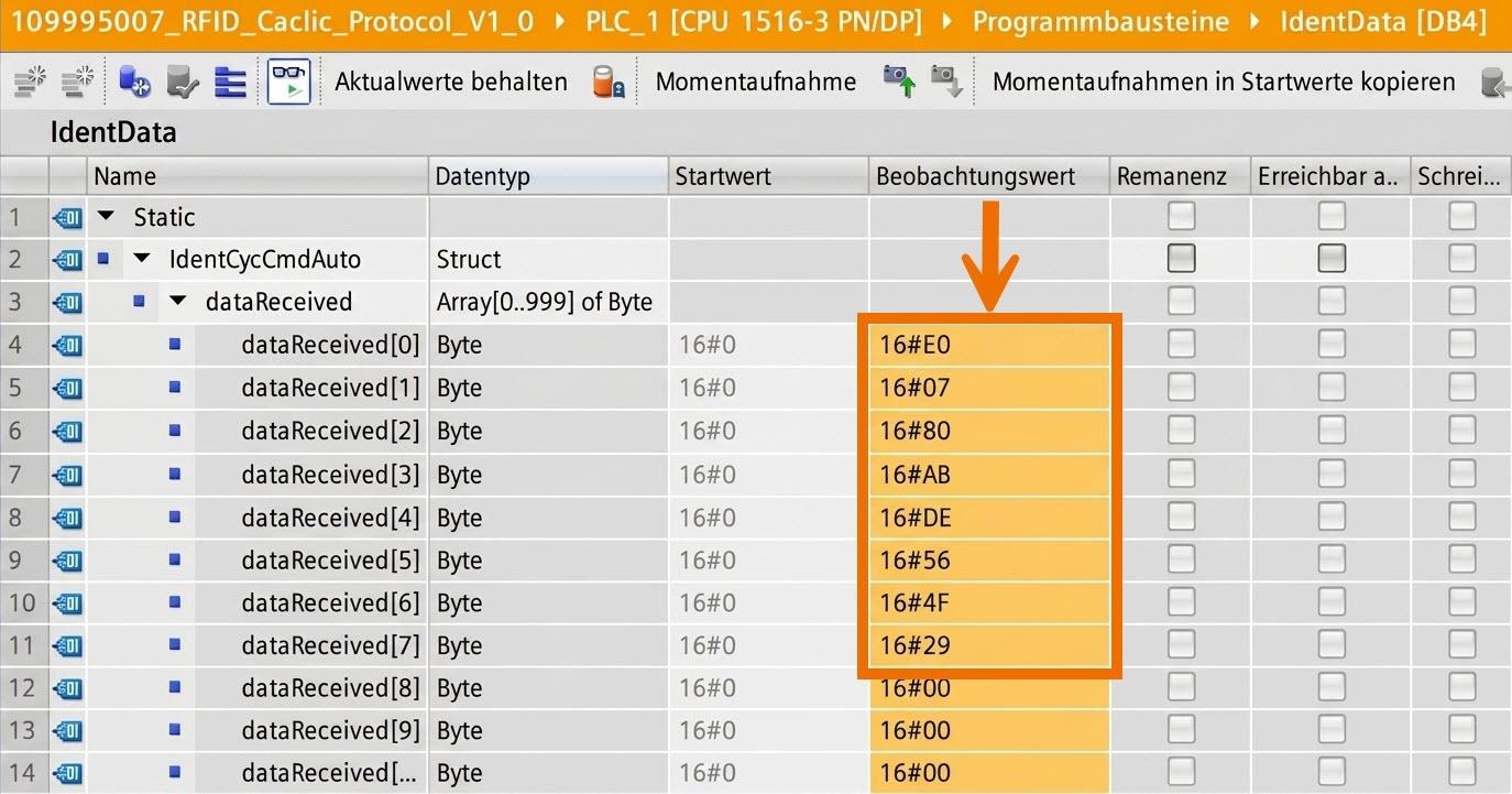
Evaluating the received UID from the telegram happens through 'IdentData's online view, since its array is linked to the 'dataRx' input.
Manual Function Block Operation – Read UID Command
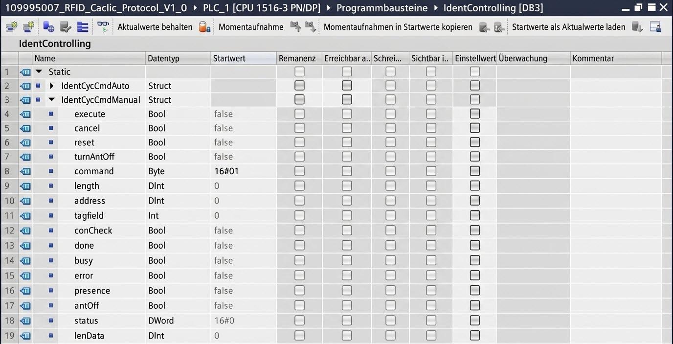
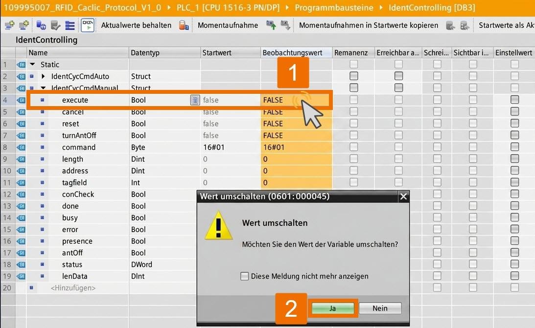
Reading the UID through the Manual FB means changing the parameters in 'IdentCycCmdManual', located inside the 'IdentControlling' data block, to match the displayed values.
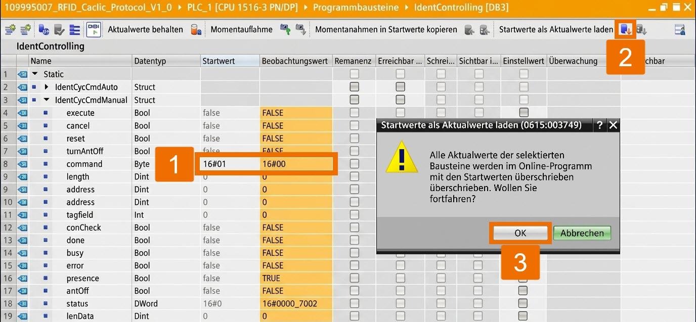
Compile the program and send it to your controller. In TIA Portal, switch to online view to check the parameterized block's current values. If online transfer of the values didn't happen, choose the 'Load starting values as current values' option and verify the note that pops up with OK.
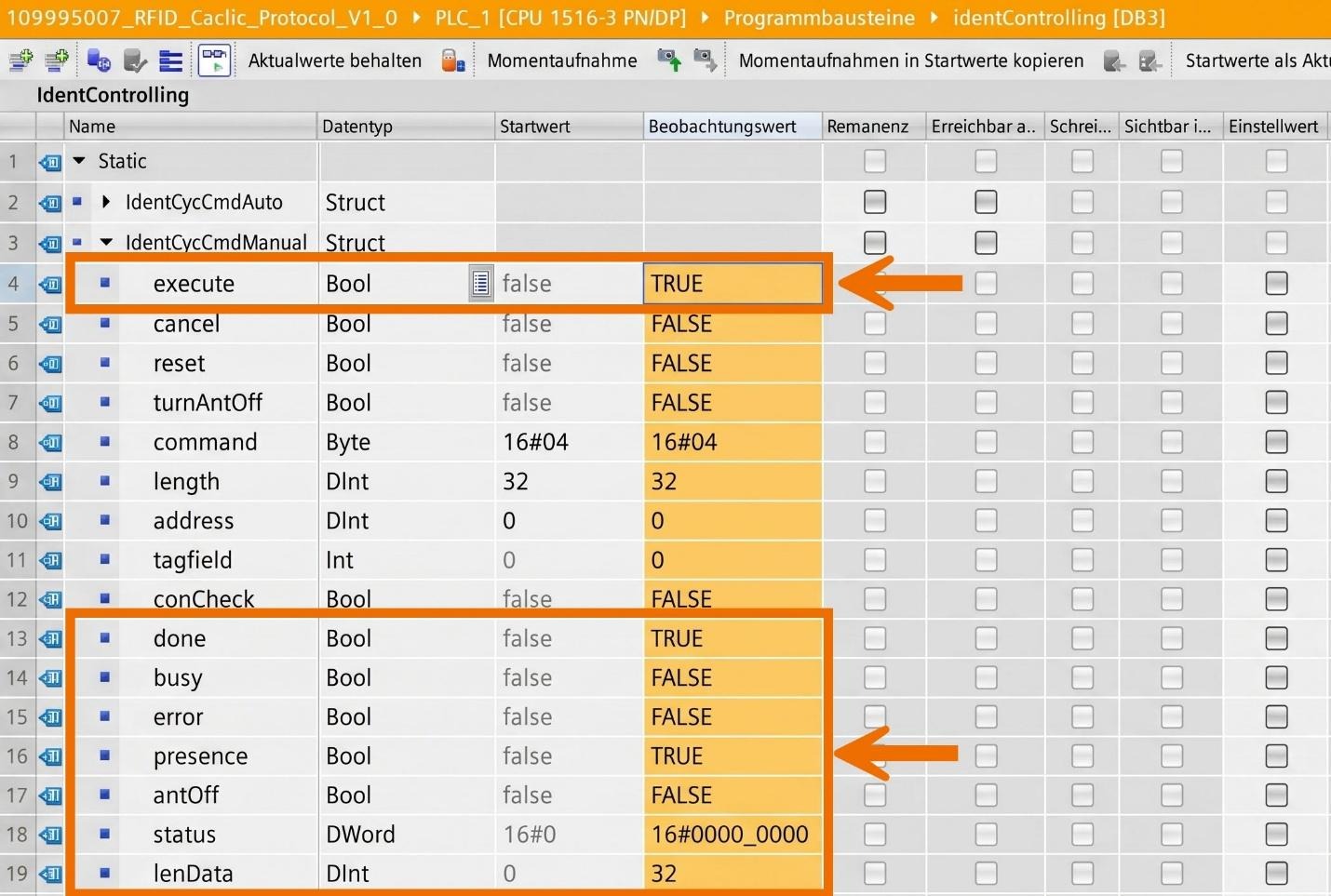
Toggling 'Execute' from FALSE to TRUE is what triggers and runs the command.
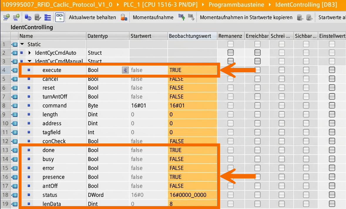
The device's outputs let you check the function block's execution. How? Once a tag is detected, outputs should show the following values.
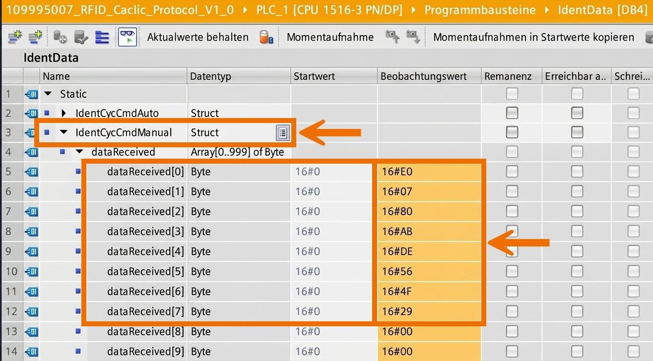
Now check the variable tied to 'dataRx'; its current value shows the UID stored from the transponder that was read.
Manual Function Block Operation – General Read Command
Configuring the parameters of 'IdentCycCmdManual' found in the table below is necessary to read transponder data.
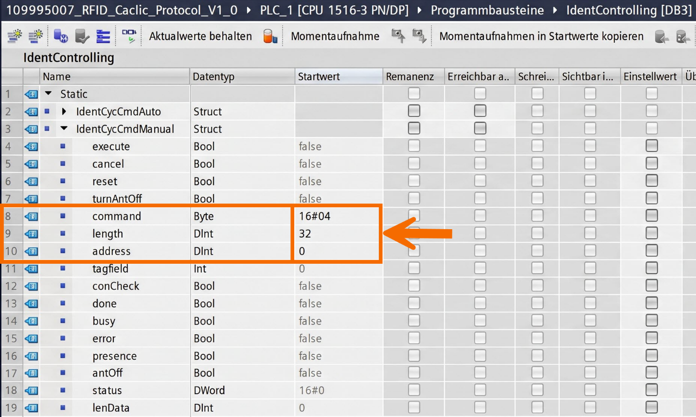
Compile the program, then transfer it to your controller. Use TIA Portal's online view to check what current values the parameterized function block is showing. Flip the 'Execute' input from FALSE to TRUE to run the command. Checking whether the function block executed correctly means watching the device's outputs.
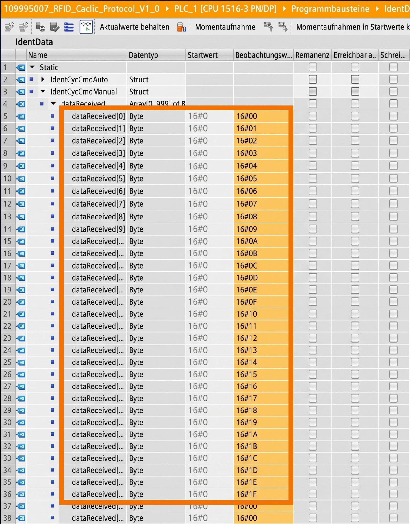
Next, check the variable you've linked to the 'dataTx' input. Displayed here are the stored values from the transponder's user memory, spanning address 0 to 31.
Manual Function Block Operation – Write Command
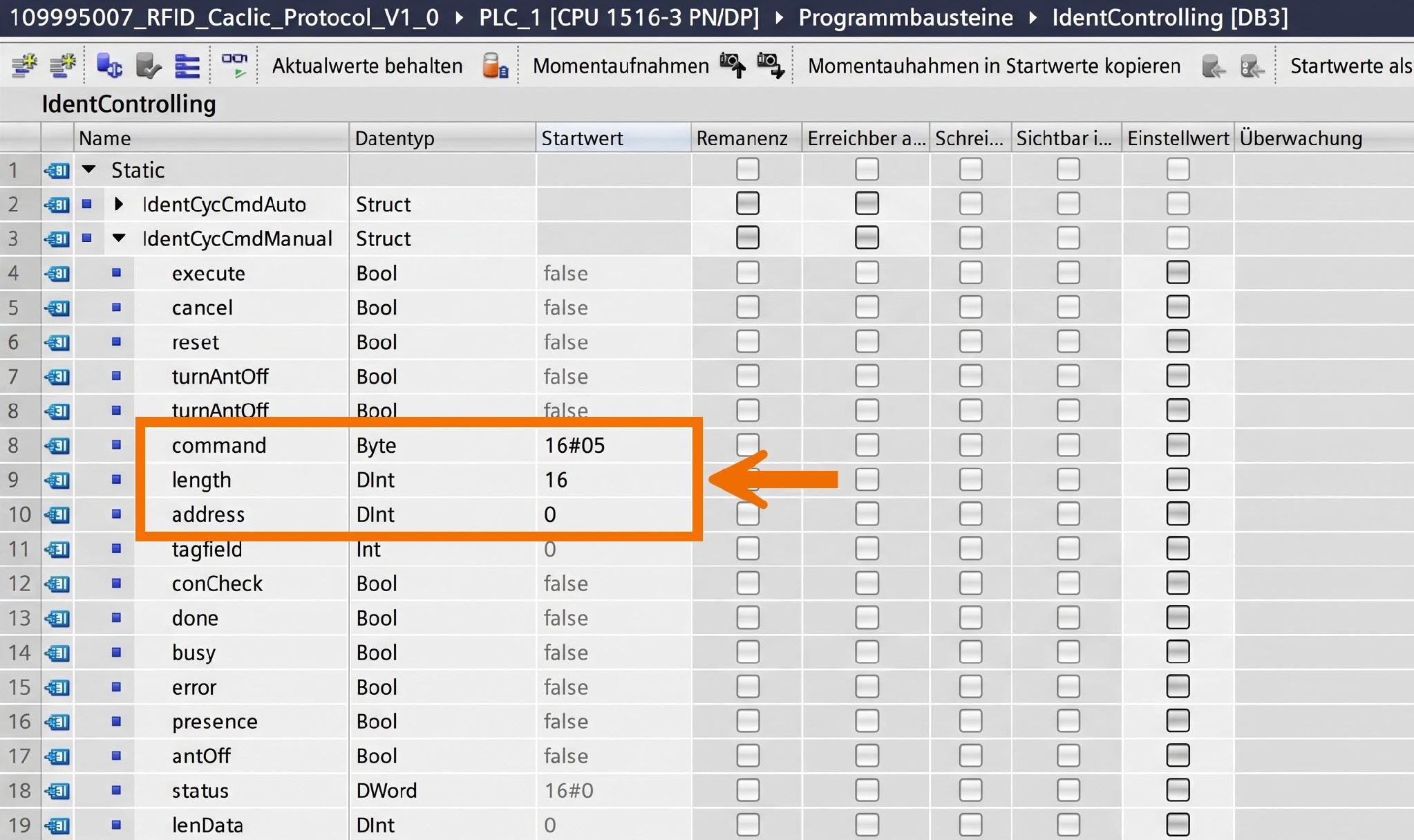
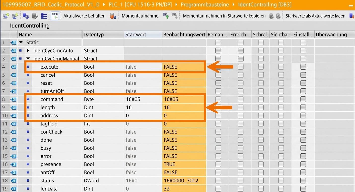
Setting up a Write command means parameterizing the function block's inputs using the configuration shown.
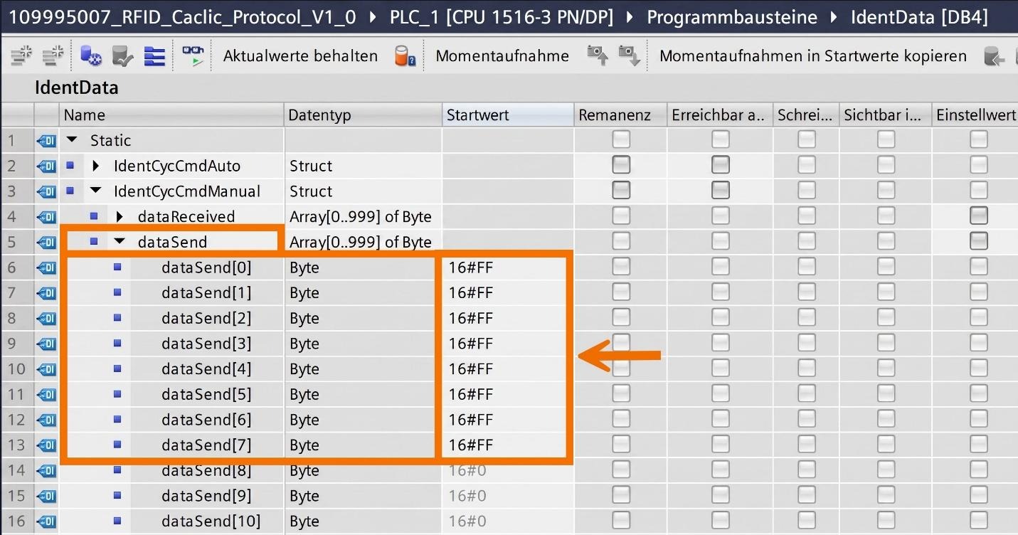
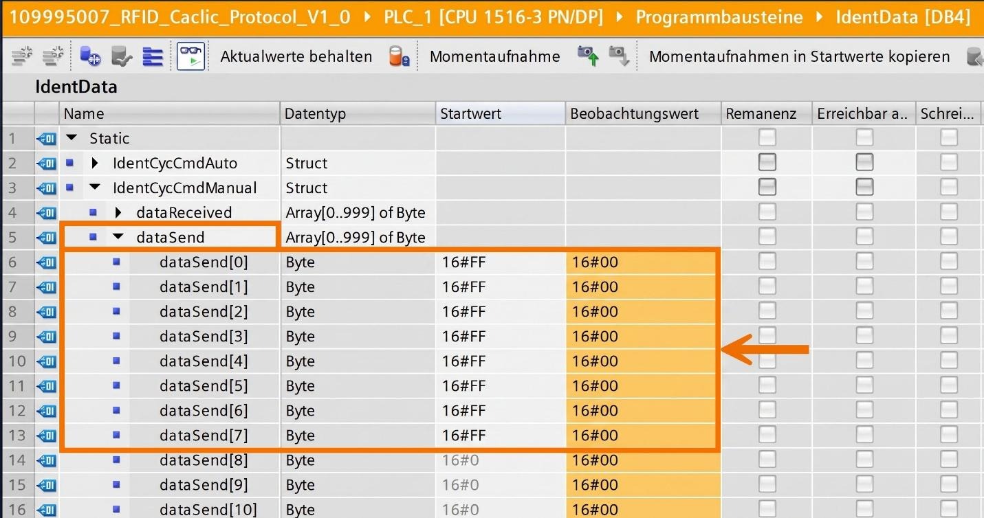
Open the 'dataSend' variable, part of the 'IdentCycCmdManual' struct in the 'IdentData' data module, and set it up individually based on the data you want written.
After loading the compiled program onto your controller, go to the online view of 'IdentControlling' to view the function block's current values.
Apply the same step to the IdentData module, reviewing and tweaking 'dataSend' within 'IdentCycCmdManual' until the online and offline values match up.
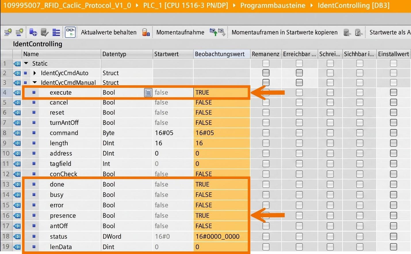
Back in 'IdentControlling's online view, the command runs once you switch the 'Execute' input from FALSE to TRUE. You can confirm the function block executed by viewing the device's outputs. The outputs should show these values once a tag is picked up.
Conclusion
In conclusion, you have learned how to set up cyclic PROFINET I/O communication using the LIDENT library, starting with configuring the CPU, communication module, and readers inside TIA Portal's hardware configuration. You've seen how to integrate function blocks, create IdentControlling and IdentData data blocks, and connect hardware IDs to the Auto and Manual function blocks in OB1. You now understand the difference between automatic and user-controlled command execution, how to read a transponder's UID, retrieve stored user memory data, and write new data to a tag. With these skills, you're ready to build and troubleshoot your own PROFINET-based identification applications.


