

IO-Link Configuration in Siemens TIA Portal | SolisPLC

Introduction
Overheating in control cabinets can quietly damage equipment and cause costly downtime. This tutorial shows you how to prevent that by configuring an Air Blower control unit over IO-Link in Siemens TIA Portal. You'll connect Pt100 temperature sensors and a fan bench through the IO-Link communication module on a SIMATIC ET 200SP, then configure process data and parameters using the S7-PCT tool. You will also understand how to adjust switching thresholds at runtime via a particular function block. By the end, you'll have a working, self-monitoring cooling system and the skills to adapt it to your projects.
Application Example Overview
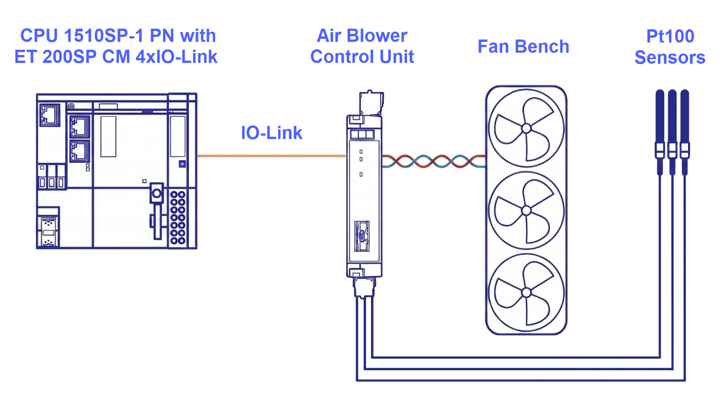
The following application example demonstrates how to plan and configure a project for a Luetze Air Blower control unit connected through IO-Link. A fan bench, Pt100 temperature sensors, and a control unit that talks to the master over IO-Link make up this system. To make this connection work, the CM 4x IO-Link communication module is wired to a SIMATIC ET 200SP. By monitoring multiple specific zones inside the control cabinet, the Luetze Air Blower setup accurately tracks temperature changes and, as a result, triggers the fan bench into action the moment it passes a pre-set limit. You can easily set up and adjust all these specific operational variables by using the S7-PCT (Port Configuration Tool) software application.
Hardware Wiring
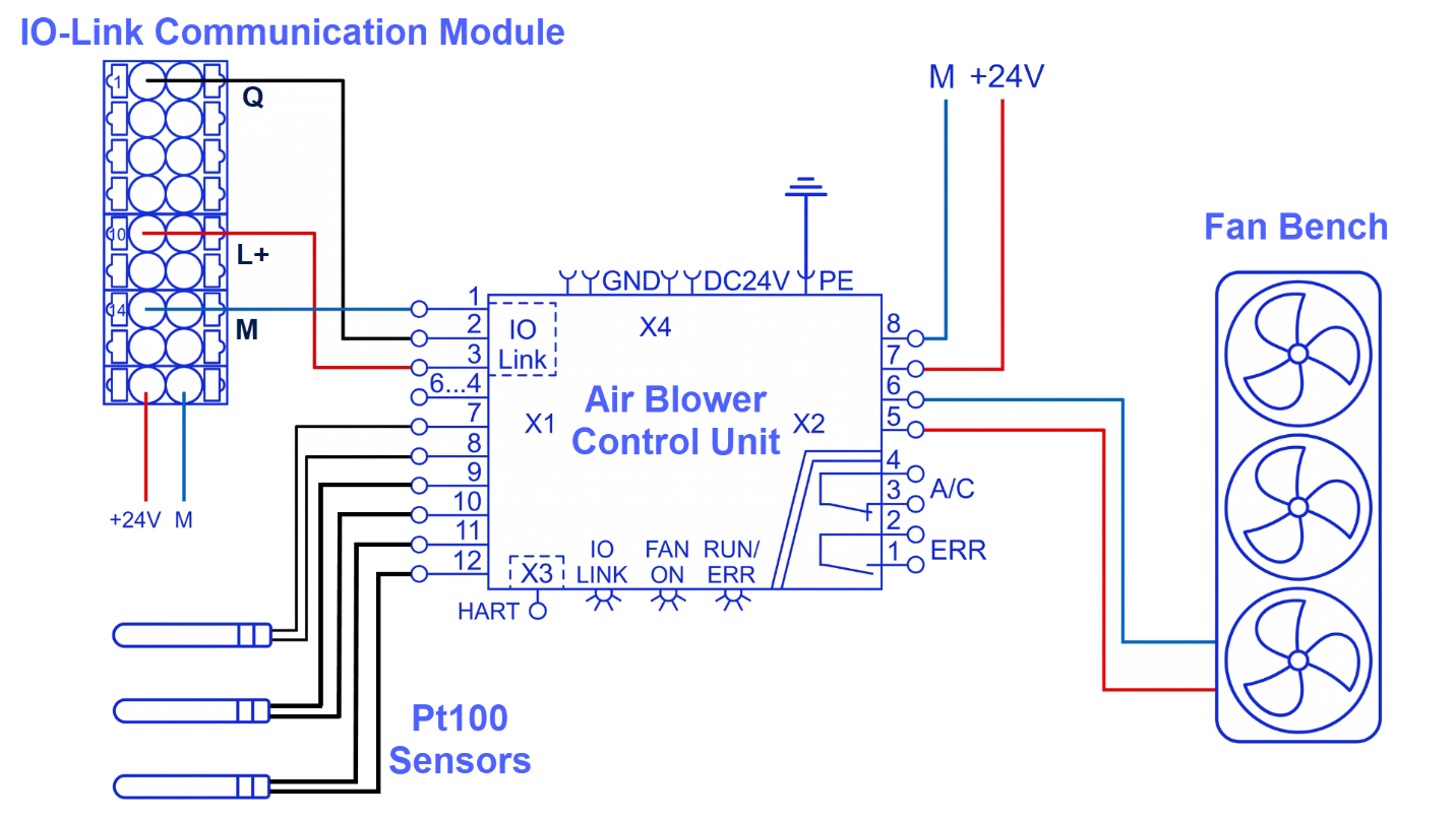
Power for the Air Blower control unit comes from a separate source; IO-Link's job here is to transfer configuration details and operational process data. Shown below is the wiring diagram between the Air Blower control unit, Pt100 elements, the fan bench, and the CM 4x IO-Link communication module. Since different temperature zones in the control cabinet need monitoring, the three Pt100 sensors are wired on terminal X1, to contacts 7 to 12. The power supply feeding the control unit and fan bench connects at terminal X2, which also offers configurable ERR and A/C contacts.
IO-Link Master Configuration
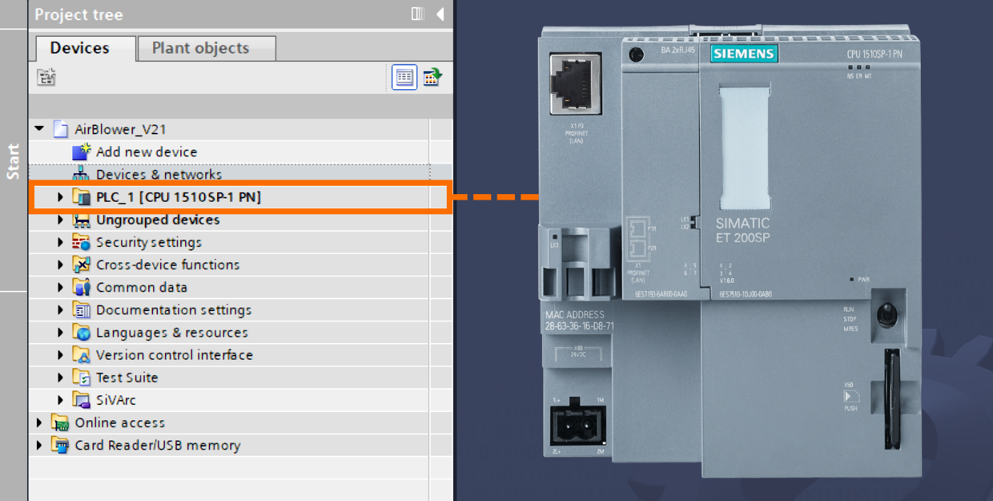
Launch the TIA Portal software, start a new project, and go with the CPU 1510SP-1 PN with ET 200SP as your chosen controller.
Start by configuring the IO-Link Master in the hardware configuration. It involves dragging the CM 4x IO-Link module from the Catalog and dropping it onto an open slot in Device View.
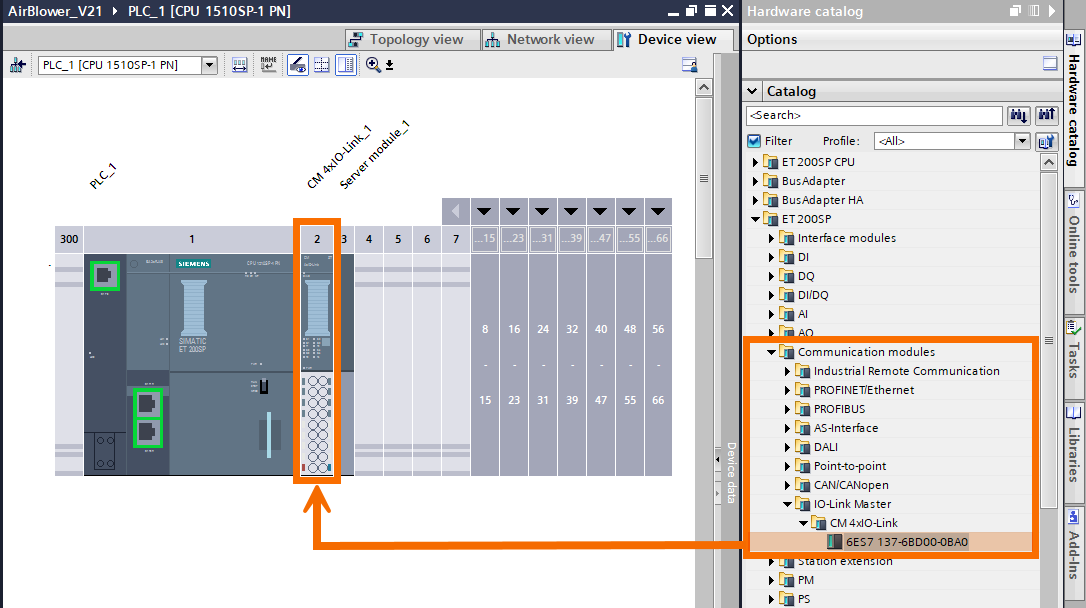
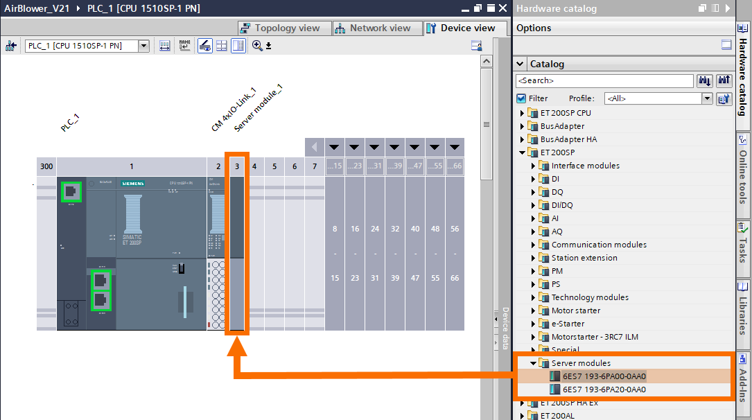
Once that's done, add a Server Module alongside the IO-Link communication module in the next free slot.
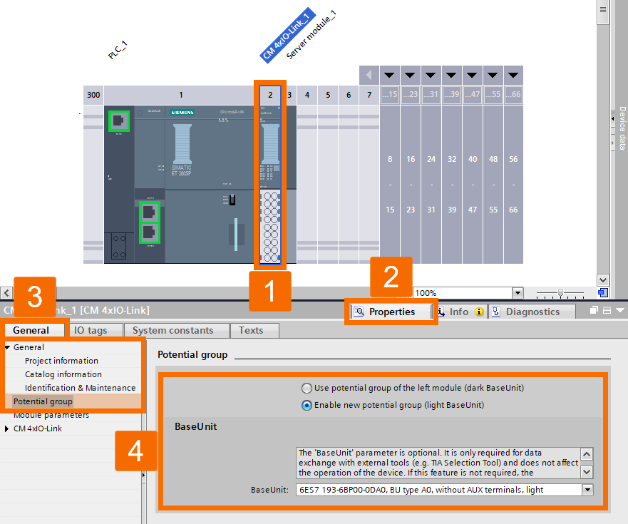
Head into module properties next, and then configure the required potential group using the settings below.
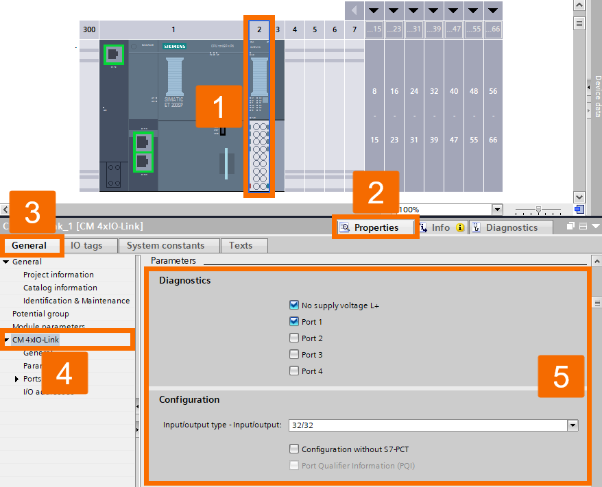
Left-click the CM 4x IO-Link item. Then, navigate to the Parameters section to set the port diagnostics and process data size, configuring 32 bytes for both the input and output.
In practice, the Air Blower control unit's process data includes both the current measured temperature and the average temperature figure for every temperature sensor. This data is saved as a UDT, short for User-Defined Type, called TypeProcessDataAirBlower within the TIA Portal project.
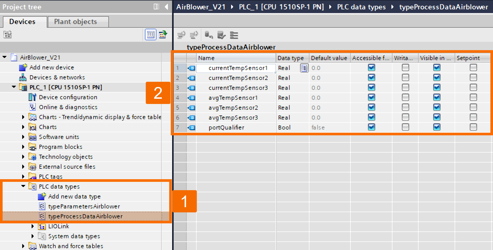
24 bytes, along with an additional 1-bit PQ, are provided by the Luetze Air Blower control unit as process values to the input addresses. Adjusting the start address is possible under the I/O addresses configuration section.
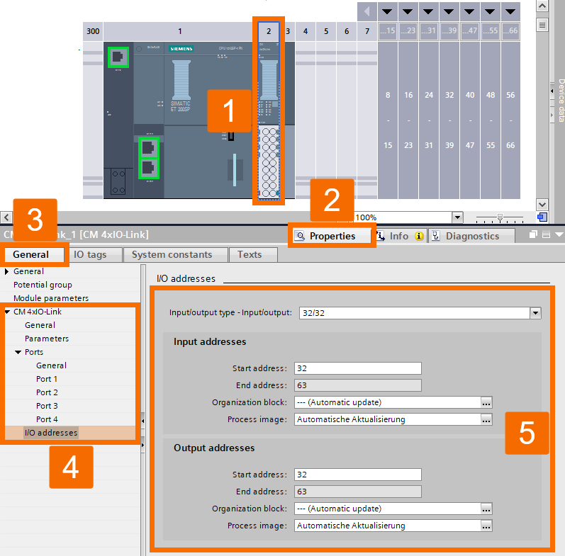
Air Blower Configuration
Configuration of the Luetze device's parameters takes place through the PCT tool. In the Device View, right-click on the IO-Link master and then choose 'Start Device Tool' from the menu.
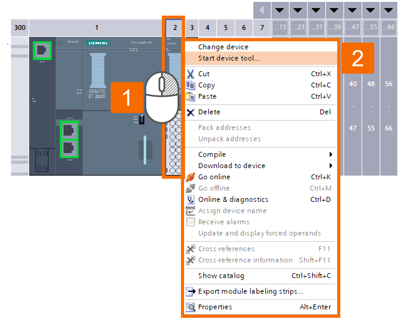
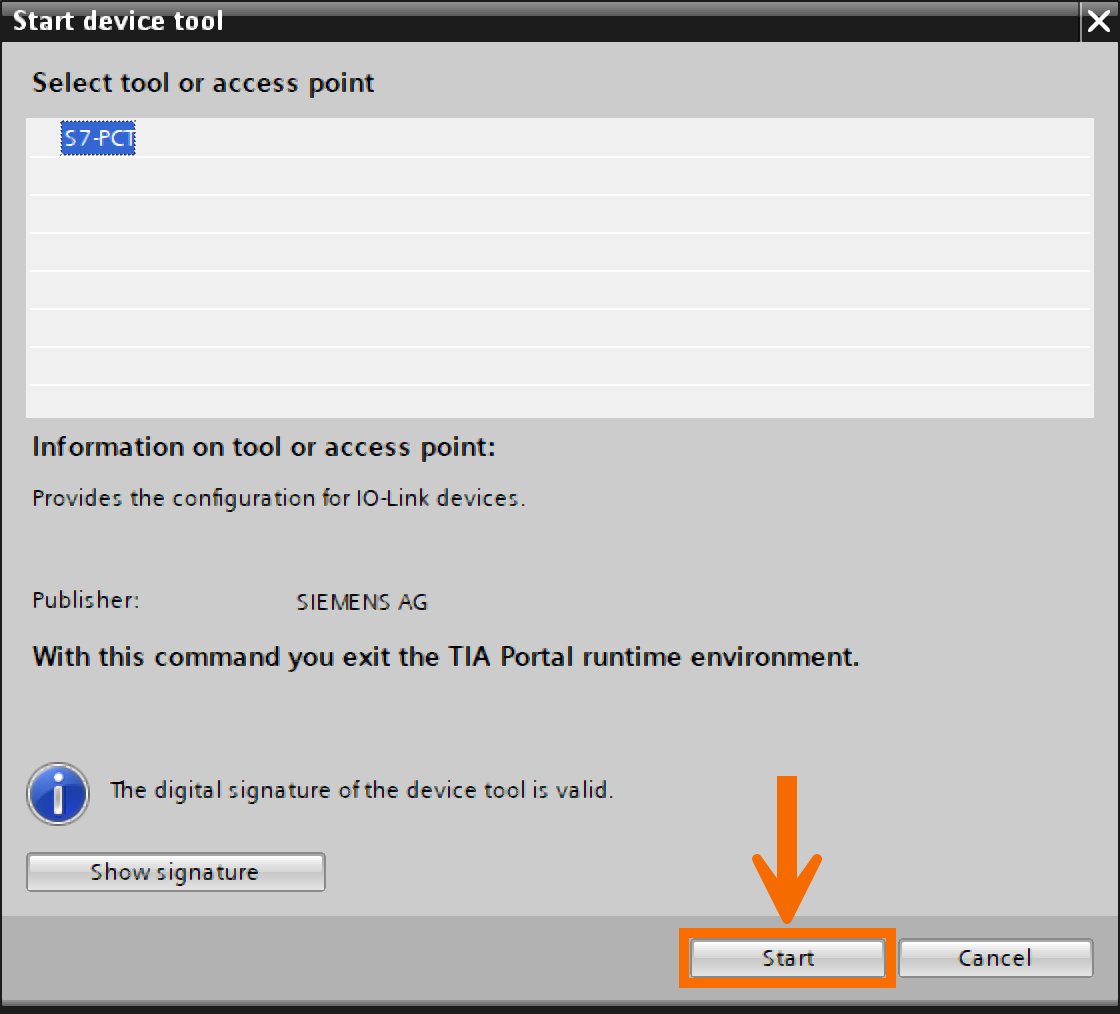
Once the 'Start Device Tool' window appears, you must click the Start button again to proceed. There's also the option to configure a PC interface beforehand, which serves as the path for loading configuration onto the IO-Link device.
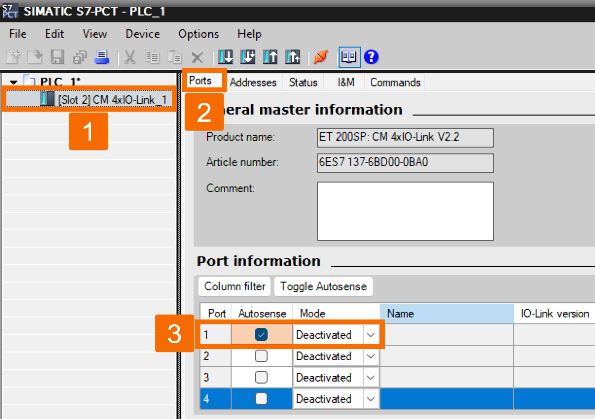
As it happens, the PCT includes an Autosense feature that automatically detects any connected IO-Link device and then downloads the corresponding IODD (IO Device Description) file. Within the project navigation pane, choose the IO-Link Master [Slot 2] CM 4x IO-Link_1, then check the Autosense box for port 1 found under the Port Information section.
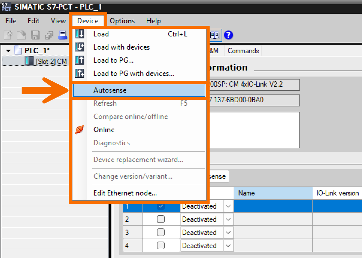
Then head to the Device menu and select the Autosense option. The 'Automatic IODD Download' window pops up at this point and requires your confirmation to proceed. The 'Import IODD Files' window then pops up, listing the IODD that has been discovered. Proceed to import the file and be sure to close the window afterward. An internet connection is required if you desire the IODD to download automatically.
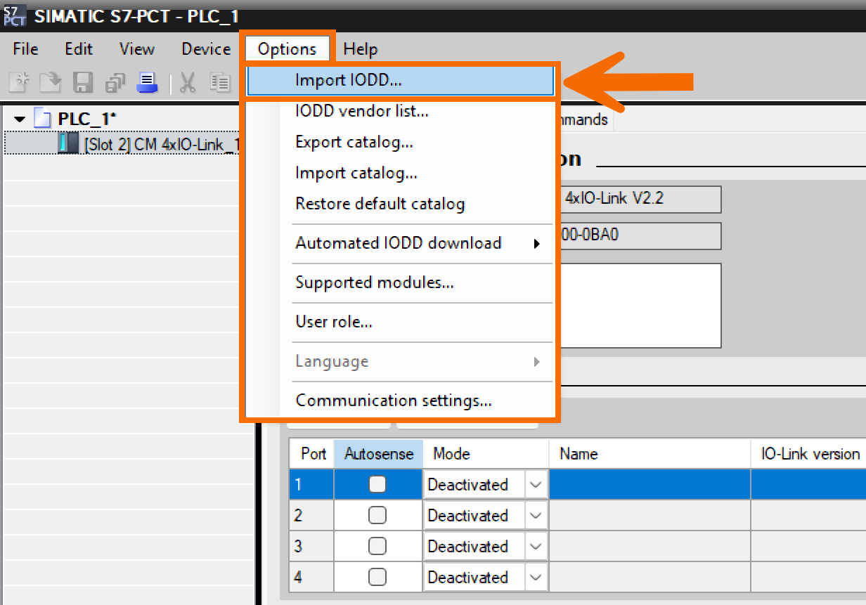
There's also the alternative of manually importing the IODD directly into the PCT. For this step, click Options first, and then left-click on the Import IODD item.
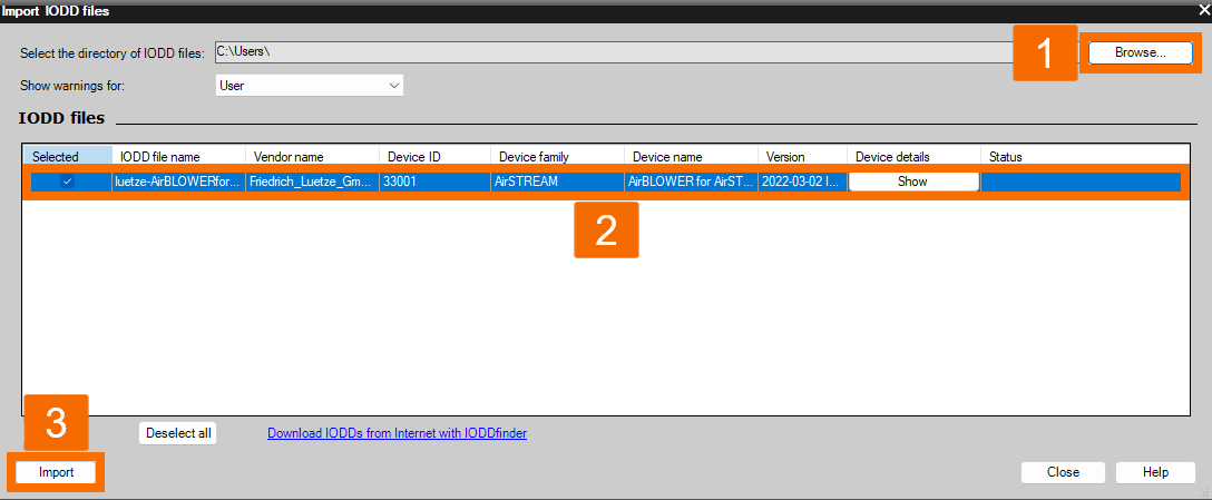
The 'Import IODD Files' dialog box then appears, allowing you to import the IODD from there. You can locate the IODD for the Luetze Air Blower by clicking this link. Then, select Import to continue.
If you look beneath the IO-Link Master within the project navigation, you'll spot the Port Information section. Using the Catalog, the IODD for the Luetze Air Blower can be dragged onto the appropriate port and dropped there. It's important to ensure the port settings in the S7-PCT correspond precisely to those configured in the TIA Portal.
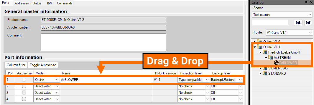
At this point, you should be able to see the Air Blower listed under the IO-Link Master in the navigation. The settings for the IO-Link device open once you click on the Air Blower entry. The Monitoring tab lets you check the current process values live, directly online.
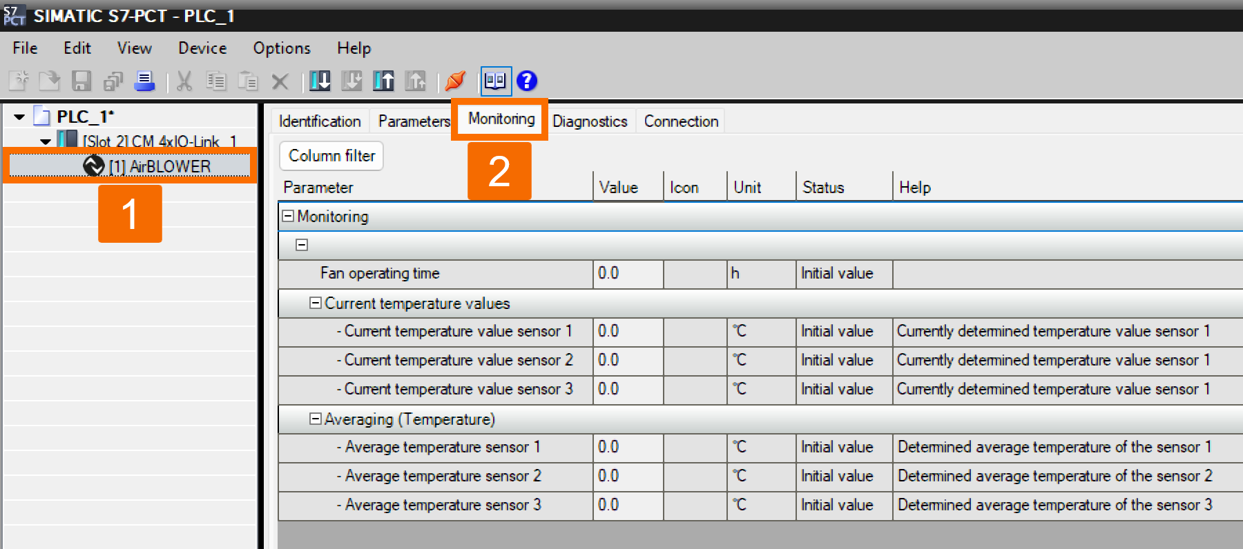
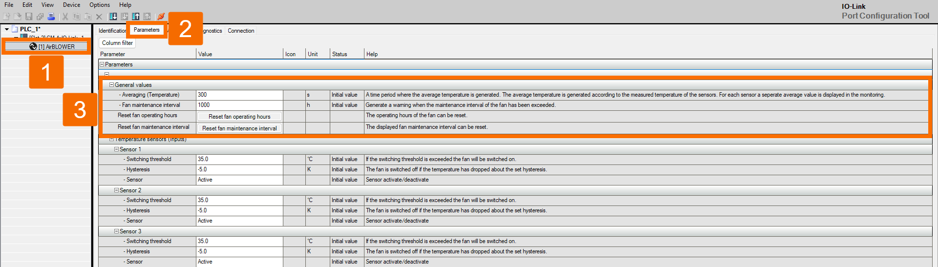
Operating limits, switching points, and additional settings can all be configured from the Parameters tab. The General Values section lets you configure the time to determine the average temperature and set a maintenance interval, too.
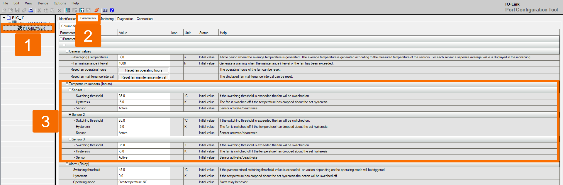
The Temperature sensor 1-3 section of the parameter list provides adjustment options for switching threshold temperature that controls the fan, the hysteresis value placed between the two-point control's upper and lower thresholds, and an option to deactivate the desired sensor.
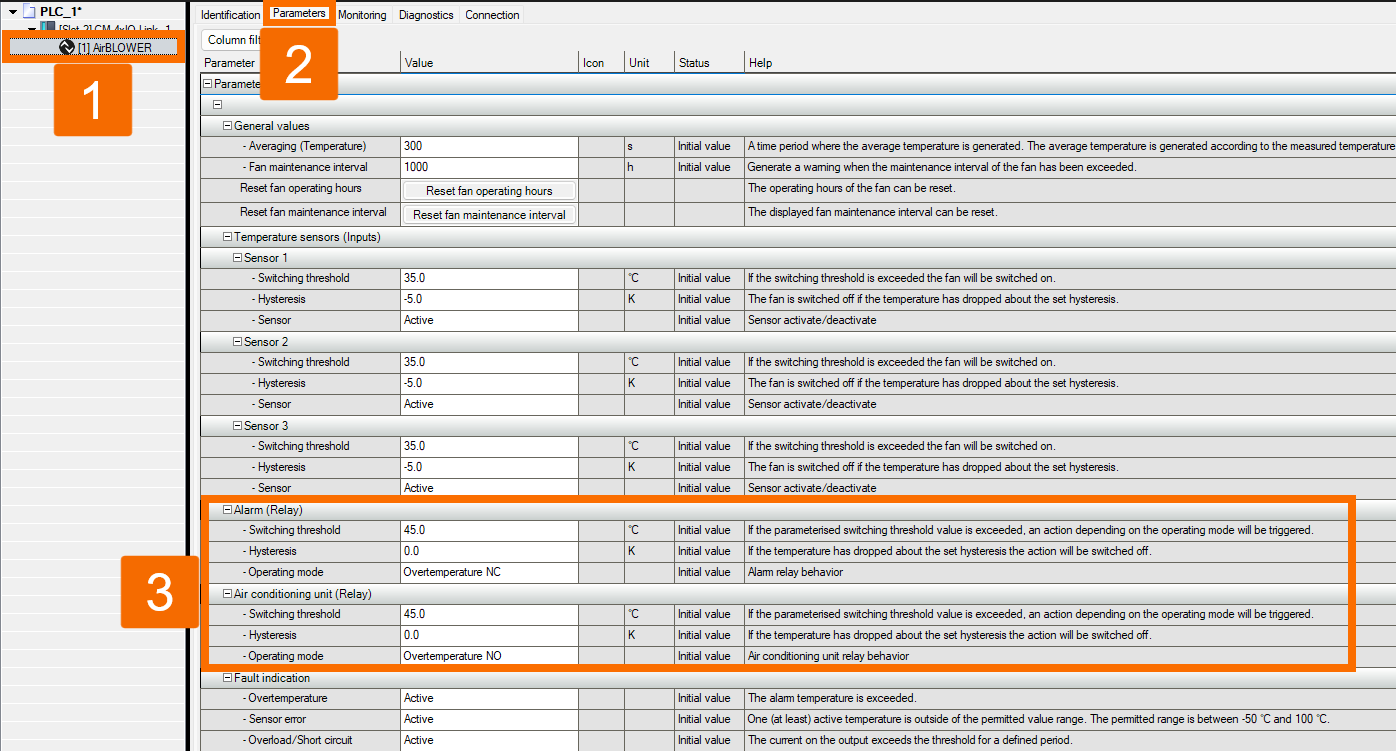
In these alarm relays and switching behavior of AC sections, adjustments can be made to the fan switching threshold, the hysteresis, and how the system behaves at overtemperature, with a possible two-stage cooling approach where Stage 1 is the fan and Stage 2 is AC cooling.
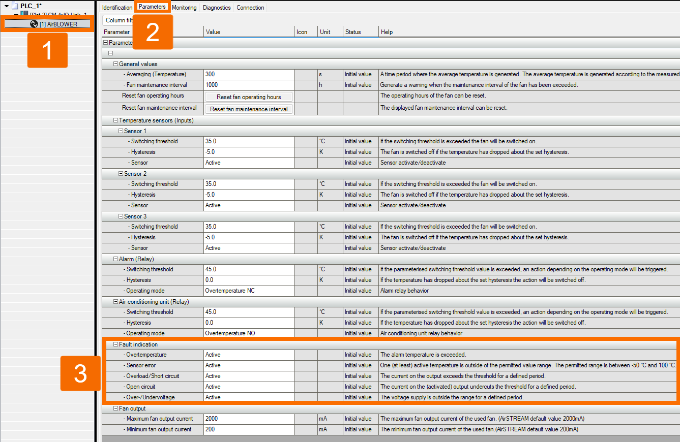
The Error detection section covers adjustable parameters for overtemperature, short circuit, and overload, sensor error, wire break detection, and over- and under-voltage conditions.
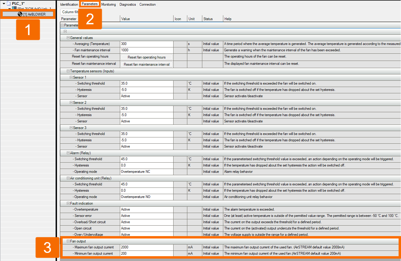
Meanwhile, within the Fan Limits section, both the maximum and minimum current values can be configured.
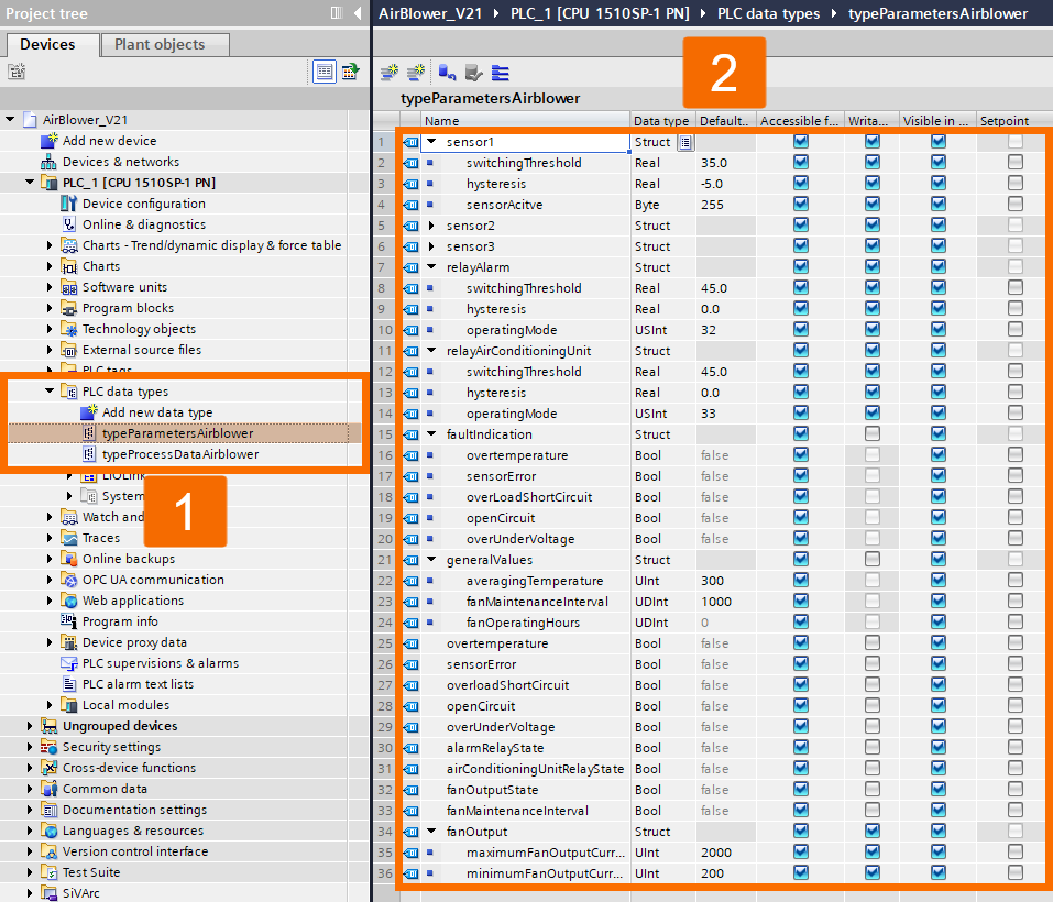
In the TIA Portal, storage of the Luetze Air Blower's parameters happens through the 'typeParametersAirblower' UDT.
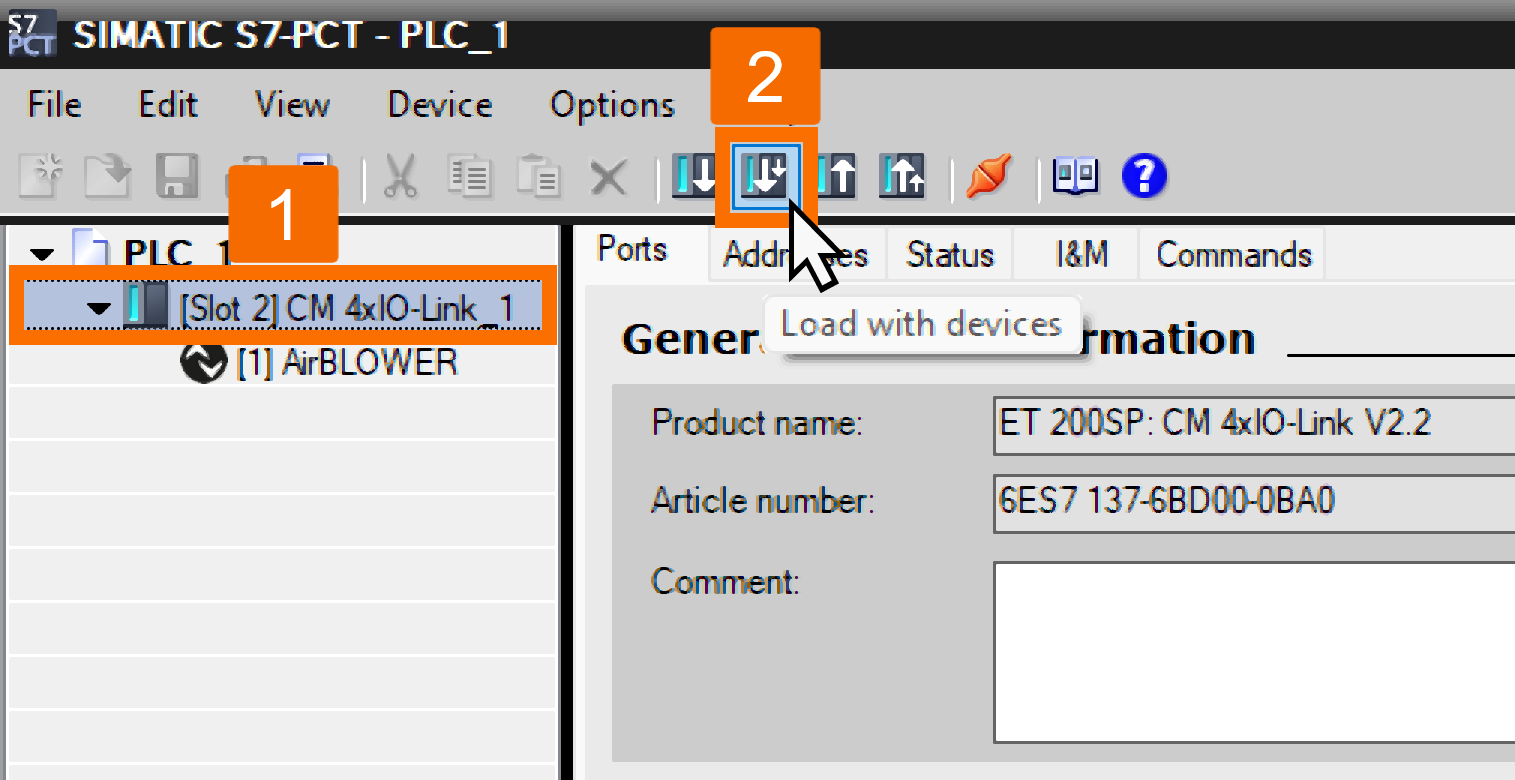
Once the Air Blower has been configured, use the 'Load with Devices' button to transfer the configuration into either the IO Link device or the controller.
Parameter Adjustment During Operation
Rather than manually configuring parameters such as switching thresholds via the S7-PCT, it's also possible to handle this task at runtime. Within the TIA Portal project, the first Pt100 element's switching threshold is reconfigured as a demonstration, changing from the standard value of 35°C down to 20°C using the function block ChangeThresholdSensor1 [FB1]. The 'LIOLink_Device' FB, taken from the 'LIOLink' library, is called from within this block, and the library itself can be downloaded through this link. Via the Control Data Block [DB1], the inputs belonging to the 'LIOLink_Device' FB are linked.
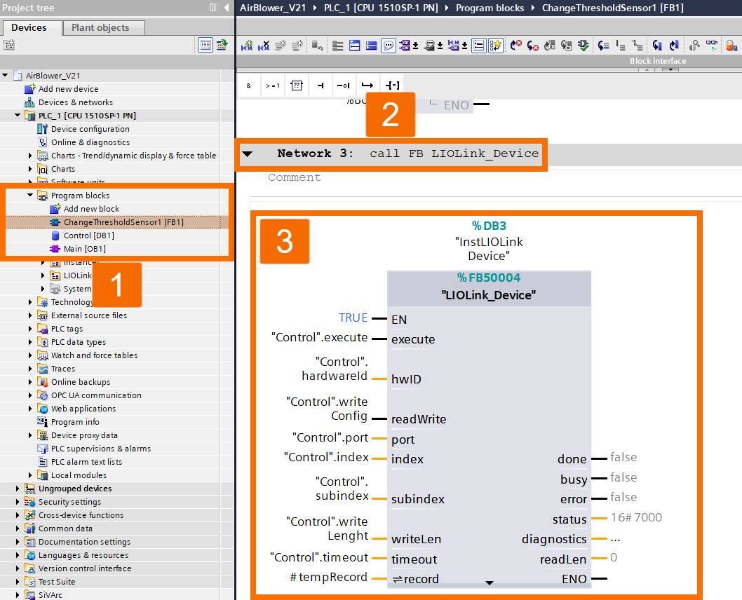
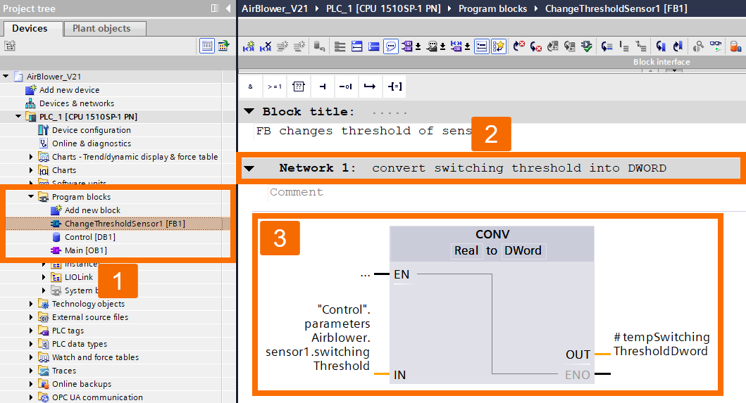
The InOut Record parameter calls for an array of bytes formatted according to the relevant data type. As a result, you must convert the first sensor's switching threshold value, currently a REAL, into the corresponding data type. First off, the conversion process changes the REAL value into a DWORD (Double Word).
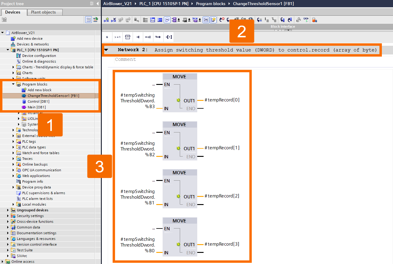
Following this step, the tempSwitchingThresholdDword takes each respective byte and maps it into the array. The first index of the array ends up holding the MSB, or Most Significant Byte, from tempSwitchingThresholdDword.
Conclusion
In conclusion, you have learned how to configure a Luetze Air Blower control unit through IO-Link in TIA Portal. It included wiring Pt100 sensors and the CM 4x module to configure process data with UDTs. You've also used the S7-PCT tool to import IODDs and fine-tune switching thresholds, hysteresis, error-detection settings, and adjust parameters dynamically at runtime via the LIOLink_Device function block. As a next step, apply these techniques to your cabinet layout, testing different thresholds and cooling stages to match your thermal needs. You're now equipped to build reliable, automated IO-Link cooling systems.


