Mapping and Configuring FANUC Robot IO Points
.jpeg)
Introduction
In this tutorial, we will cover the types of IO connections available in a Fanuc robot and the mapping and configuration of the IO points. This knowledge is necessary for most if not all robot applications as it is needed for the robot to communicate with internal and external devices. This includes but is not limited to other robots, PLCs or other controllers, internal IO, and end-of-arm tooling (EOAT).
Pre Requisites
To follow this tutorial, you will need:
- Familiarity with FANUC programming basics.
- Access to a FANUC robot or RoboGuide offline programming software.
Understanding Robot IO Types
Digital I/O
Digital I/O (DI and DO) are Boolean values representing "0" OFF and "1" ON. These Boolean values are voltage values with 0V representing Boolean "0" and the high-level voltage (typically 24V) representing Boolean "1".
Analog I/O
Analog I/O (AI and AO) are real numbers that represent a value within the voltage range of the input or output module.
Group I/O
Group I/O (GI and GO) groups input or output bits together. This grouping allows you to interpret this binary group as an integer representation.
Robot I/O
Robot I/O (RI and RO) are the inputs and outputs between the robot and the controller. Physical access to these signals is via the End Effector connector on the robot. RI and RO signals get used for IO between the controller and end effector and any other peripherals on that area of the robot arm.
User Operator Panel I/O
(UI and UO) They are used to give status or control the robot's operation. The user operator panel provides 18 input signals and up to 24 output signals that can be connected to a remote device to control the robot.
Standard Operator Panel I/O
Standard operator panel I/O (SI and SO) are internal controller digital input and output signals for controlling the operator panel on the controller. These are pre-assigned and are typically only used for displaying information.
I/O Configuration
Racks, Slots, Channel, and Starting Point
When mapping IO in a FANUC device, the programmer must understand specific terms before moving forward. These terms are "Racks," "Slots," "Channel," and "Starting Point." These legacy terms have been carried forward from when every single I/O point was physically hardwired. These terms are apparent when dealing with hardwired physical input and output cards. The terms are also for communications handled over ethernet, which is less intuitive.
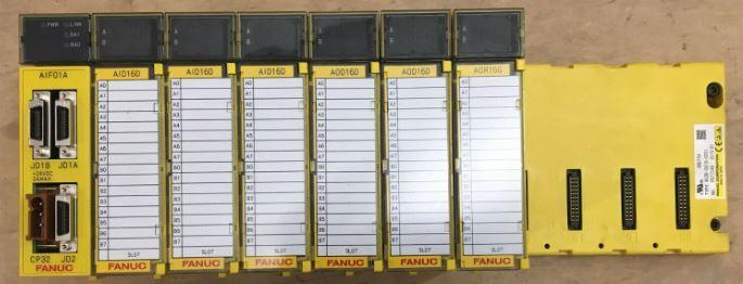

The "Rack" is the physical chassis where the I/O module is mounted when using I/O modules. The term "Rack" also defines the specific type of I/O and interface used for communication, with each "Rack" representing a different interface type even if there is no physical "Rack" interface.
For example:
- Rack 0: Process I/O boards
- Rack 66: Profibus DP master
- Rack 81: DeviceNet
- Rack 85: ControlNet
- Rack 89: EthernetIP
- Rack 106: EtherCat
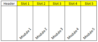
The "Slot" is the location on the "Rack" where the I/O is connected. For standard I/O, it is the connection point of the module to the "Rack." The "Slot" is similar to the "Rack" in that meaning can vary depending on the type of I/O.
For example:
- Modular I/O: "Slot" refers to the space on the "Rack" where the I/O module is connected.
- Distributed I/O: "Slot" refers to the DIP switch settings on the unit.
- DeviceNet: "Slot" number refers to the MAC id
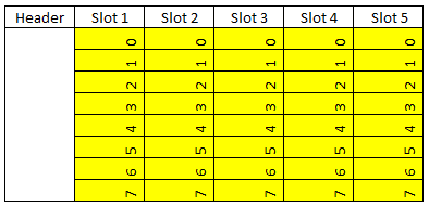
When referring to analog I/O only, FANUC uses the term "Channel." This "Channel" is the terminal number on the I/O module where the I/O point is connected. The "Starting Point" is only used when referring to Digital, Group, and UOP I/O. The "Starting Point" is also used to refer to the terminal number on the I/O module.
Configuring Fanuc Robot I/O
With the hardware installed and with all the I/O points wired, the I/O needs to be configured. The configuration of analog and digital I/O can be done automatically by the System under certain conditions but let's take an example of the manual configuration of a set of Digital IO.
We do this by following the below steps:
- Take the Teach Pendant and ensure the key is in the "On" position.
- Press Menu
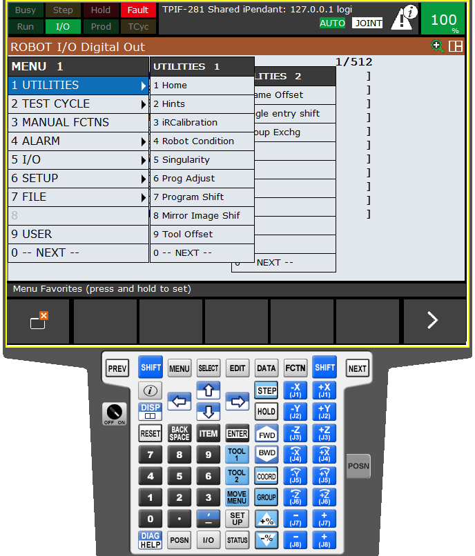
- Select 5: I/O
- Select 3: Digital
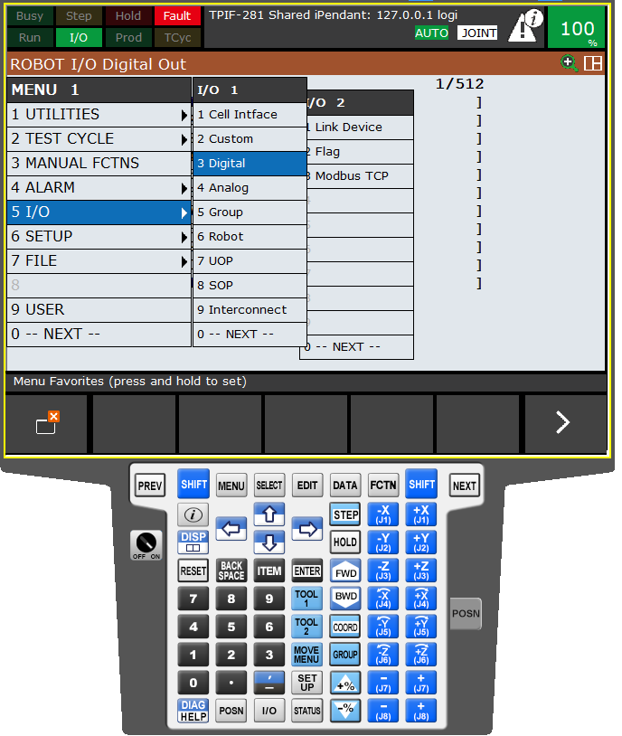
- You will see a screen similar to the one shown below. The I/O points are currently unavailable since the configuration still needs to be completed.

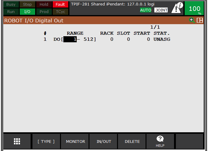
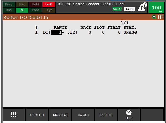
- To configure the I/O, press the "CONFIG" button, which will bring you to the configuration screen. As standard, there are 512 points available for configuration. Pressing the IN/OUT button will change the screen between inputs and outputs. Since we have not configured anything, the System's status is "UNASG" (Unassigned).
There are four possible statuses for the System. These are:
- ACTIV (Active): Assignment is valid and active
- INVAL (Invalid): The assignment is invalid and incorrect based on the hardware
- PEND (Pending): The assignment is valid but needs a system restart before taking effect
- UNASG (Unassigned): No assignment has been made
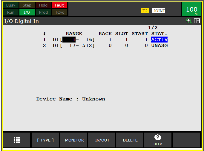
- We will assign two 16-channel I/O modules to the "Rack" (Rack 1). These will be a 16-channel input card and a 16-channel output card. You start by configuring the range; in this case, since our cards are 16 channel, the range value is 1-16. Our input card is in "Slot" 1 of our "Rack." Our output card is in "Slot" 2 of our Rack, so these values get set respectively. Since we have no other I/O assigned to the terminal of these modules, we will set our "Start" value at 1. Therefore DI[1] = Input 1, DI[2] = Input 2 and so on. The same goes for the output assignment.
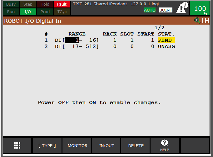
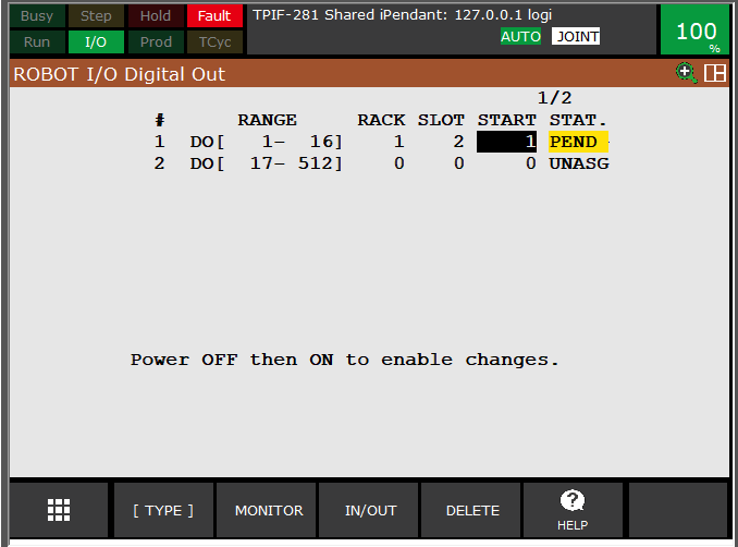
- Once we make the changes, the system "Status" will change to "PEND" (Pending). We must reboot the controller at this point.
- After the restart, our system status will now be "ACTIV" (Active), meaning that our I/O configuration was correct and successful.
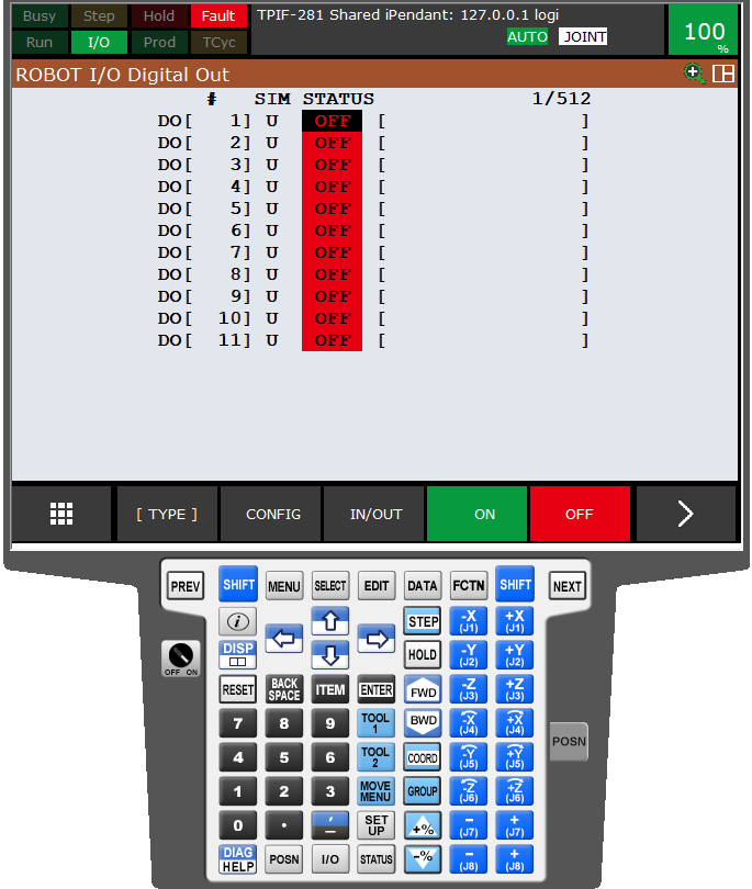
- Moving back to the "Monitor" page, the individual I/O points status gets shown. Currently, all statuses are "OFF." When input arrives on the input module's terminal or when we set output from the robot, these statuses' will get updated to "ON."
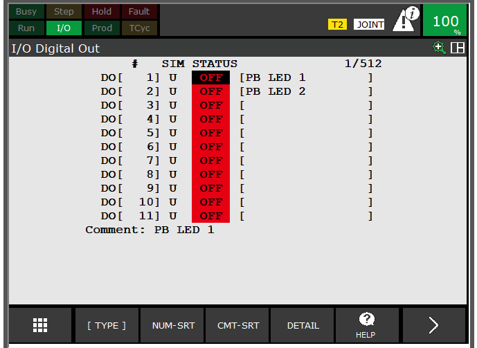
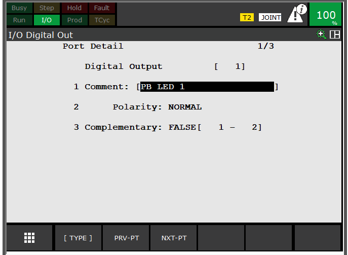
- The I/O can now be configured further by going into each I/O point "Detail" sub-menu. Items include:
- Adding a comment to describe the signal.
- Setting the polarity of the signal.
- Setting a complementary pair.
Simulateing I/O
Simulating I/O values is helpful for testing software and fault finding. It allows the user to simulate an input or output value without sending or receiving the signal. Both inputs and outputs can be simulated in the “OFF” state and the “ON” state. Digital, analog, robot I/O and group signals can be simulated but not SOP or UOP signals.
To simulate a signal, the I/O needs to first be configured correctly. Once configured, enter the I/O monitoring page of the signal which is intended to be simulated. On the top of this page is a column named “SIM”.

The I/O point can then be simulated by moving to the intended location on this column and pressing the “SIMULATE” button. The “SIM” column status will change from “U” for unstimulated to “S” for simulated to indicate the change.
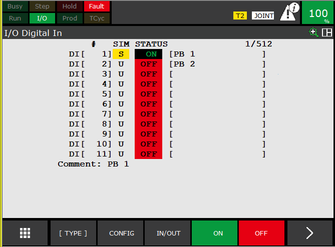
Once set to simulate the “STATUS” value can then be changed to either “ON” or “OFF”, allowing the user to then use this feature in the robot software.
Conclusion
Configuring I/O is crucial knowledge required for robotics programming. It is how the robot communicates with its environment during operation.
This tutorial covered the types of I/O signals available to the robot programmer in a FANUC robot. We have also covered how to configure standard Digital input and Output points and how to simulate these signals for use in the robot software. Finally, regardless of the type of I/O used, the configuration in a FANUC robot follows the same if not a similar procedure but requires correct assignment of the "RACK," "SLOT," "CHANNEL," and "START" parameters.
