MicroLogix 1100 RSLogix 500 External IO PLC Programming Tutorial

MicroLogix 1100 PLC Programming
The MicroLogix 1100 PLC is still heavily used in the industry and is one of the most recommended PLCs for learning PLC programming. The MicroLogix 1100 PLC is compact, offers a variety of I/O configurations and is inexpensive relative to other Rockwell options. Furthermore, the MicroLogix 1100 PLC is programmable using the free version of RSLogix 500 that can be downloaded from the official Rockwell website.
Is MicroLogix 1100 Obsolete?
No, the MicroLogix 1100 PLC is not obsolete. Based on the Rockwell Compatibility Centre, the controller is currently labeled as “active mature”. In other words, it will not be developed any further, but it is considered stable for industrial automation use.
How do I get RSLogix 500 for Free?
RSLogix 500 Lite is available directly from Rockwell Automation. To download the software, one needs to create a free account, search the database and download RSLogix as well as RSLinx. We wrote a complete tutorial on the exact steps for the download and installation: Download, Install and Run RSLogix 500 for Free.
What software does MicroLogix use?
As mentioned above, the MicroLogix 1100 Allen Bradley PLC uses RSLogix 500 software.
MicroLogix 1100 - External I/O Installation
Just like many other types of PLCs, the MicroLogix series offers the user a way to extend the Input and Output count through various external modules. Here’s what’s available for the MicroLogix PLCs
Digital MicroLogix 1100 Modules
- 1762-IA8 | 8-Point 120V AC Input Module
- 1762-IQ8 | 8-Point Sink/Source 24V DC Input Module
- 1762-IQ8OW6 | 8 Point Sink/Source 24V DC Input/6-Point AC/DC Relay Output Combination Module
- 1762-IQ16 | 16-Point Sink/Source 24V DC Input Module
- 1762-OA8 | 8-Point 120/240V AC Triac Output Module
- 1762-OB8 | 8-Point Sourcing 24V DC Output Module
- 1762-OB16 | 16-Point Sourcing 24V DC Output Module
- 1762-OW8 | 8-Point AC/DC Relay Output Module
- 1762-OW16 | 16-Point AC/DC Relay Output Module
- 1762-OX6I | 6-Point Isolated AC/DC Relay Output Module
- 1762-OV32T | 32-Point Solid State 24V DC Sink Output Module
- 1762-OB32T | 32-Point Solid State 24V DC Source Output Module
- 1762-IQ32T | 32-Point DC Input Module
Analog MicroLogix 1100 Modules
- 1762-IF4 | 4-Channel Voltage/Current Analog Input Module
- 1762-OF4 | 4-Channel Voltage/Current Analog Output Module
- 1762-IF2OF2 | Combination 2-Channel Input 2-Channel Output Voltage/Current Analog Module
Specialty MicroLogix 1100 Modules
- 1762-IR4 | 4-Channel RTD/Resistance Input Module
- 1762-IT4 | 4-Channel Thermocouple/mV Input Module
Although the functionality of each module is different, the procedure to add each module to the platform is the same.
Step 1 - Install the MicroLogix Hardware
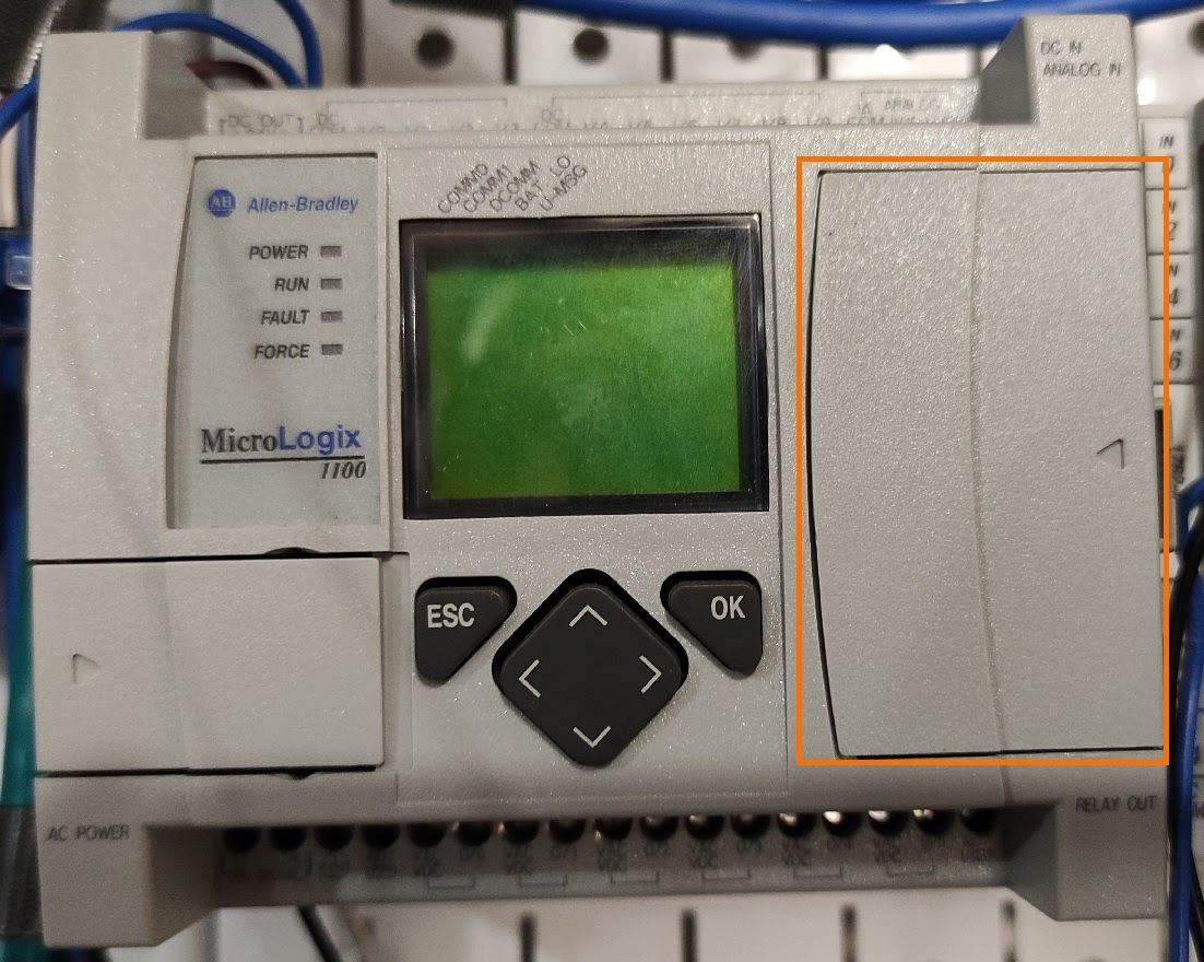
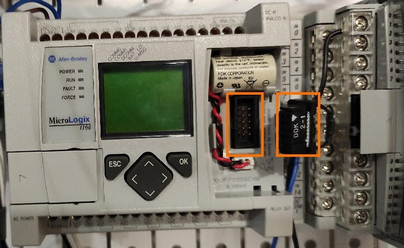
The MicroLogix 1100 PLC, as well as the other ones using the same modules, have a connector on the left side. This connector is initially hidden by the factory cover. To remove the cover, the user can utilize his fingers or a small tool; we recommend a 3mm flathead screwdriver. Under the cover, the user will find a battery as well as the connector.
The battery is responsible to keep the volatile memory of the PLC while it is powered down. In these older systems, an array of settings, including the IP address is stored into volatile memory. Therefore, a battery is required to save the IP upon a power outage. Note that this line of PLCs does not provide an indication of a bad battery similar to what one may be used to on the ControlLogix line.
Step 1.1 - Power Down the System
Although Rockwell allows the system to accept modules while it is powered-up, it is always safer for the electronics as well as the person performing the operation to add these modules while the PLC and the external hardware are powered down.
Step 1.2 - Remove the front Cover
Remove the cover shown below.
Step 1.3 - Plug the External Module into the MicroLogix 1100 Port
Under the cover; you’ll find a port that will mate with the ribbon cable connector you have on the external module. Plug the module into the port as shown below.
Step 1.4 - Add Additional Modules [Optional]
The MicroLogix 1100 PLC is capable of handling up to four external modules from the list above. Adding a secondary module requires the user to remove the cover on each subsequent module and plug in the same plug of the next module into the current one. The end result should have the MicroLogix 1100 on the left with one to four modules daisy-chained on the right.
Step 1.5 - Replace the cover(s) and Power On
Once you’ve added all the modules to the MicroLogix, replace the covers that have been removed and restore power to the PLC.
Step 2 - RSLogix Programming
How do I connect my MicroLogix 1100?
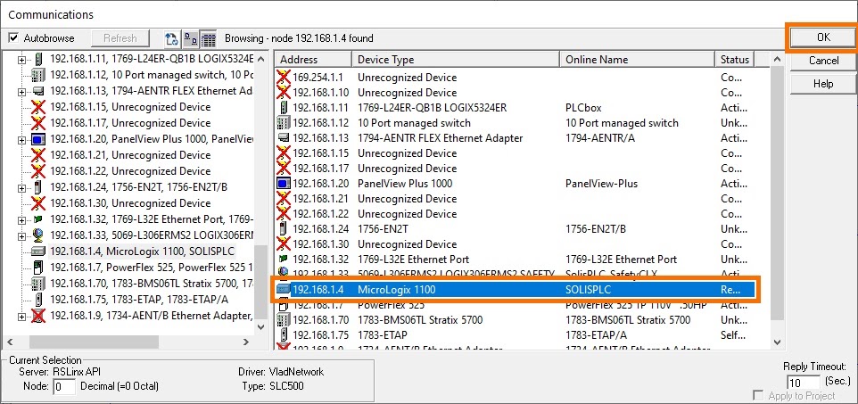
Now that the hardware is powered on, we can connect to the PLC. We’ve covered the steps needed to establish communication, set the IP through BootP and go Online with the PLC in a previous tutorial; you can find it here in case you need a refresher: How to Use BootP / DHCP Tool to Set an IP and Go Online.
Step 2.1 - Backup Existing Software
In a plant setting, it is critical to create a backup of your software during any modification of the system. When you perform the changes we’re about to execute, you’ll have to download to the PLC. By downloading, we will erase the program if we choose to overwrite what’s already there. Therefore, it is important to create a backup.
Go online with the PLC
Once online, hit “Save” to backup the latest program.
Go Offline.
Step 2.2 - Add External I/O Modules in MicroLogix 1100 Configuration
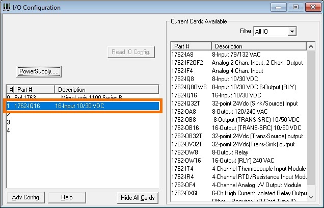
Open the “IO Configuration” menu located in the IO Tree on the left hand side.

By double-clicking or dragging the appropriate cards, specify the modules that have been added to the system.
Note: the modules must be in the same order as they were attached to the MicroLogix 1100 PLC.
Step 2.3 - Utilize I/O from External Modules
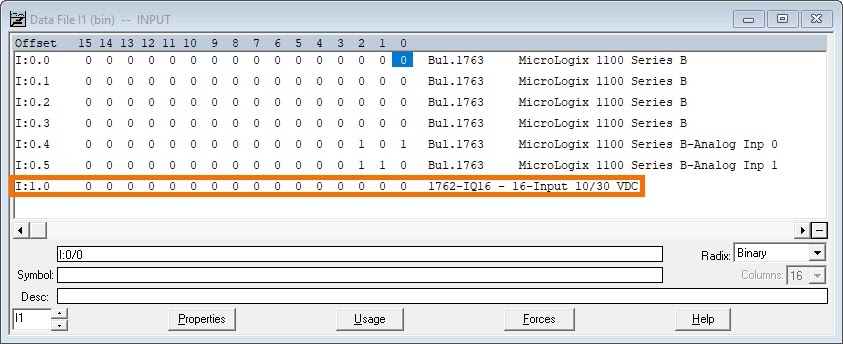
Once you have configured the I/O cards, you can utilize their values in RSLogix 500. You will find all the Output data under the “O0 - OUTPUT” register and the Input data under the “I1 - INPUT” register.
Note: the data for each module will be organized under the slot that was specified in your configuration file. In other words, the data sent by or to the module in slot 1 will start with O:1.x or I:1.x. (As shown below).
In the case of a 16-Input Digital Input card as shown in our example, it is possible to create basic logic to verify the functionality of the module. The rung below is using the first input on the card to set an internal bit within the PLC.
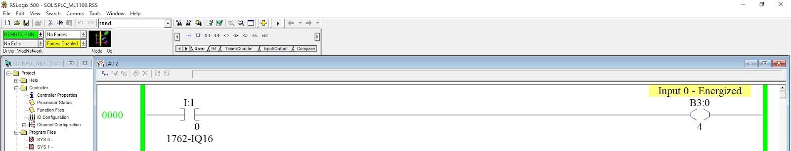
Note: the programmer may use each one of the bits specified in the software with the reference to the sensors or external devices that are connected to each input on this external card. The input bits would therefore be: I:1/0, I:1/1, I:1/2, … , I:1/15. (This only applies to this specific module).
Step 2.4 - Download the Program
Now that we’ve configured the card, the bits and the logic, we can proceed with the download to the MicroLogix 1100 PLC. At this point, the program will utilize the IO we’ve added through the external module. In the video tutorial posted below, we’ve included a basic test using a SICK sensor.
Conclusion on MicroLogix 1100 External IO Implementation
We’ve covered how to connect an external IO expansion module to our MicroLogix 1100 series PLC. We then modified an existing RSLogix 500 program that was running on the PLC; we’ve added a structure for the input card that we selected and logic that it tied to the same I/O points. Lastly, we’ve downloaded the modified program into the PLC and tested the I/O we’ve added.
