Configuring Modbus RTU Communication in Siemens TIA Portal

Introduction
In industrial communication, Modbus RTU (Remote terminal unit) is one of the most universal and accepted protocols used owing to the fact that numerous automation systems have Modbus-RTU interfaces for communication. Modbus RTU offers some advantages over TCP, one such advantage is in the area of long-distance communication. RTU can be transmitted in well over 1000 meters as compared to TCP which is 100 meters without using repeaters.
In this tutorial, we will learn how to configure Modbus RTU in Siemens TIA Portal as both master and slave. To configure S7 PLCs as Modbus TCP on TIA Portal, take a look at our previous tutorial on Modbus TCP communication in Siemens TIA Portal.
Prerequisite
In order to follow along with this tutorial, you will need:
- An understanding of Modbus Protocol. You can look up our introductory tutorial
- An installation of Tia Portal. In this tutorial, we will be using TIA Portal V16.
- An installation of Modbus Poll (a simulation software that serves as a Modbus master)
- An installation of Modbus Slave (a simulation software that serves as a Modbus slave)
Creating a new project in TIA Portal
Launch TIA Portal and add a new device. We will be adding an S7-1200 PLC. The exact configuration will work with S7-1500. Modbus RTU cannot be simulated with PLCSIM because MODBUS RTU is a serial device.
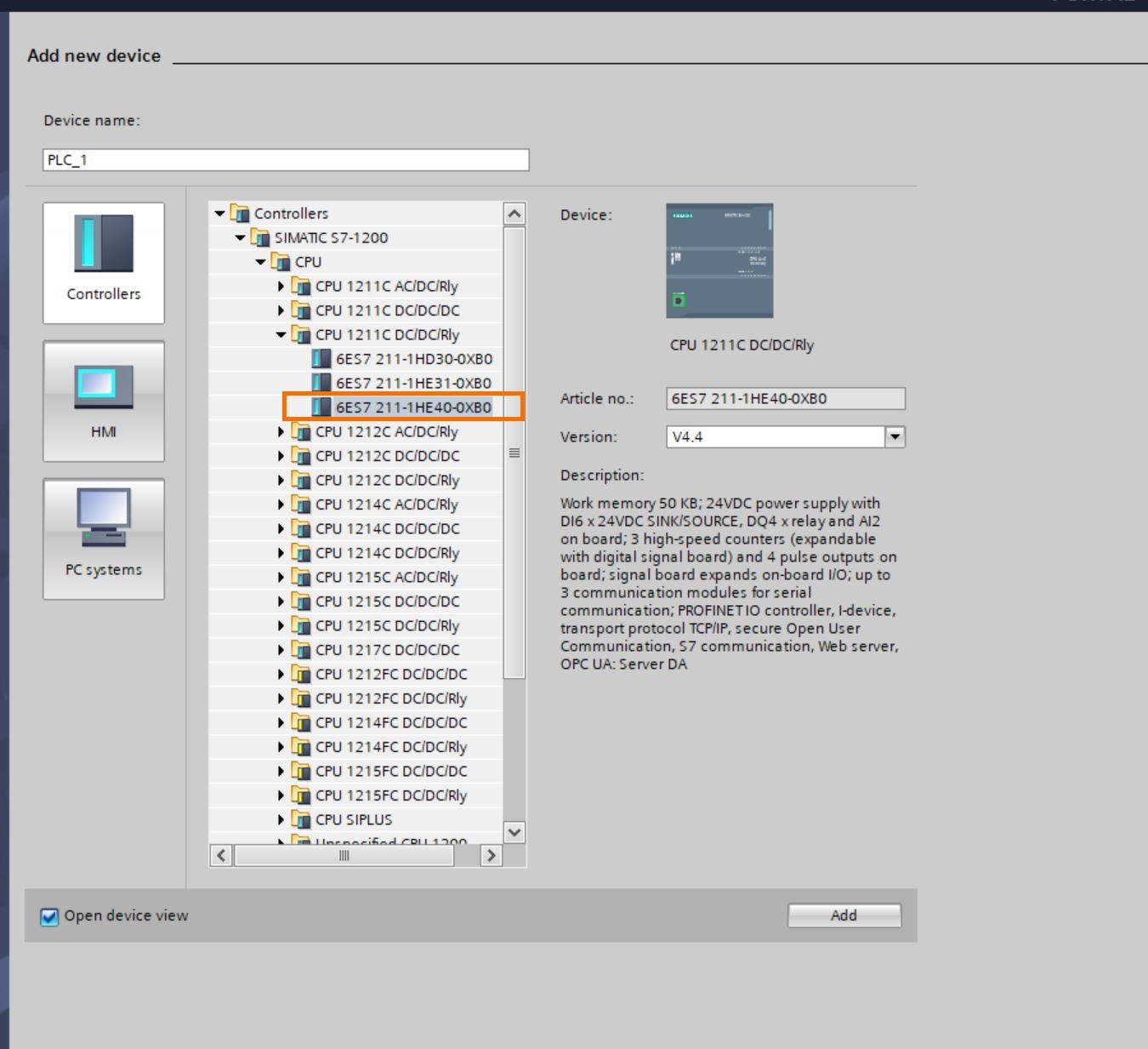
Adding a new communication device
To be able to use Modbus RTU, a new device that supports Modbus RTU will be added. The device CB 1241 (RS 485) is used in this tutorial. This device is capable of communicating over a serial RS 485 network.
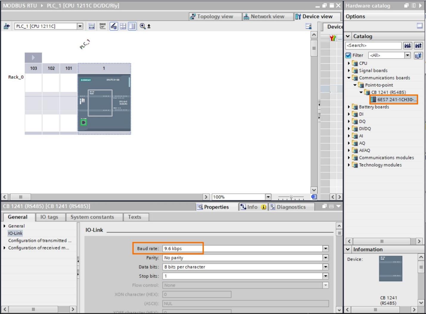
Navigate to device configuration on the project tree, then at the right side under Catalog, select Point-to-point and pick the RTU device.
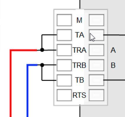
Wiring the CB 1241 module
The CB 1241 module is wired as shown on the image to the right. A and B goes out to the other Modbus RS 485 device.
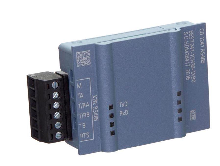
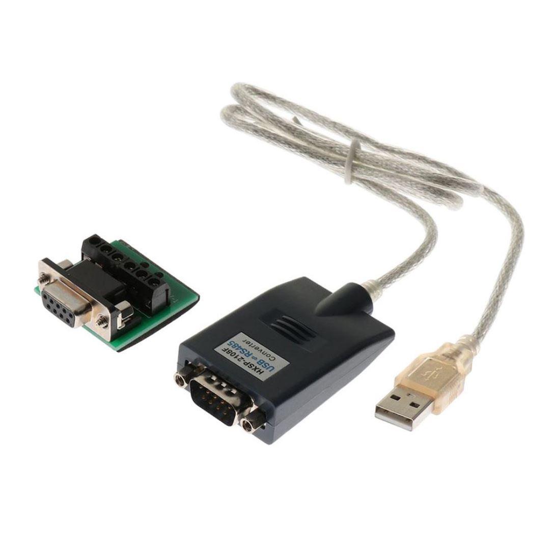
A USB to RS 485 device can be used for connection if no other physical Modbus compatible device is available such as the one in the image below
Configuring a Modbus communication block
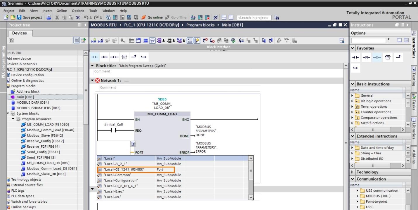
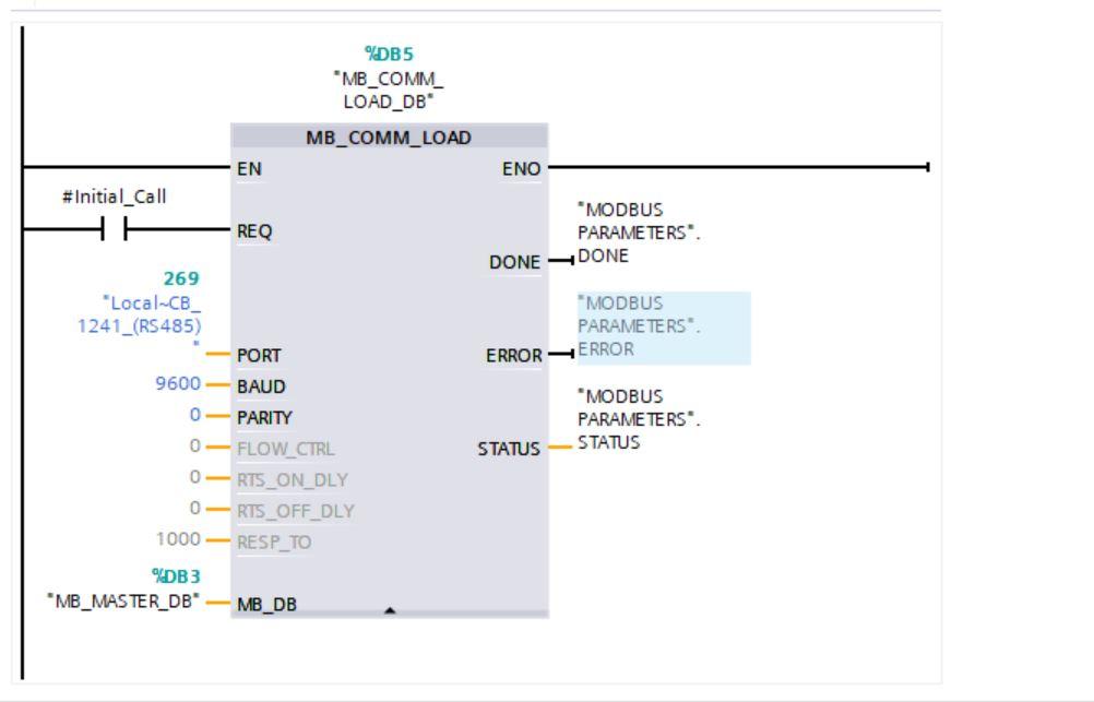
To configure Modbus RTU in TIA Portal, you need to configure the communication block. Navigate to communication and select Modbus then select the MB_COMM_LOAD block. The baud rate is 9.6kbps or 9600. The blocks look exactly like what is seen in the next image.
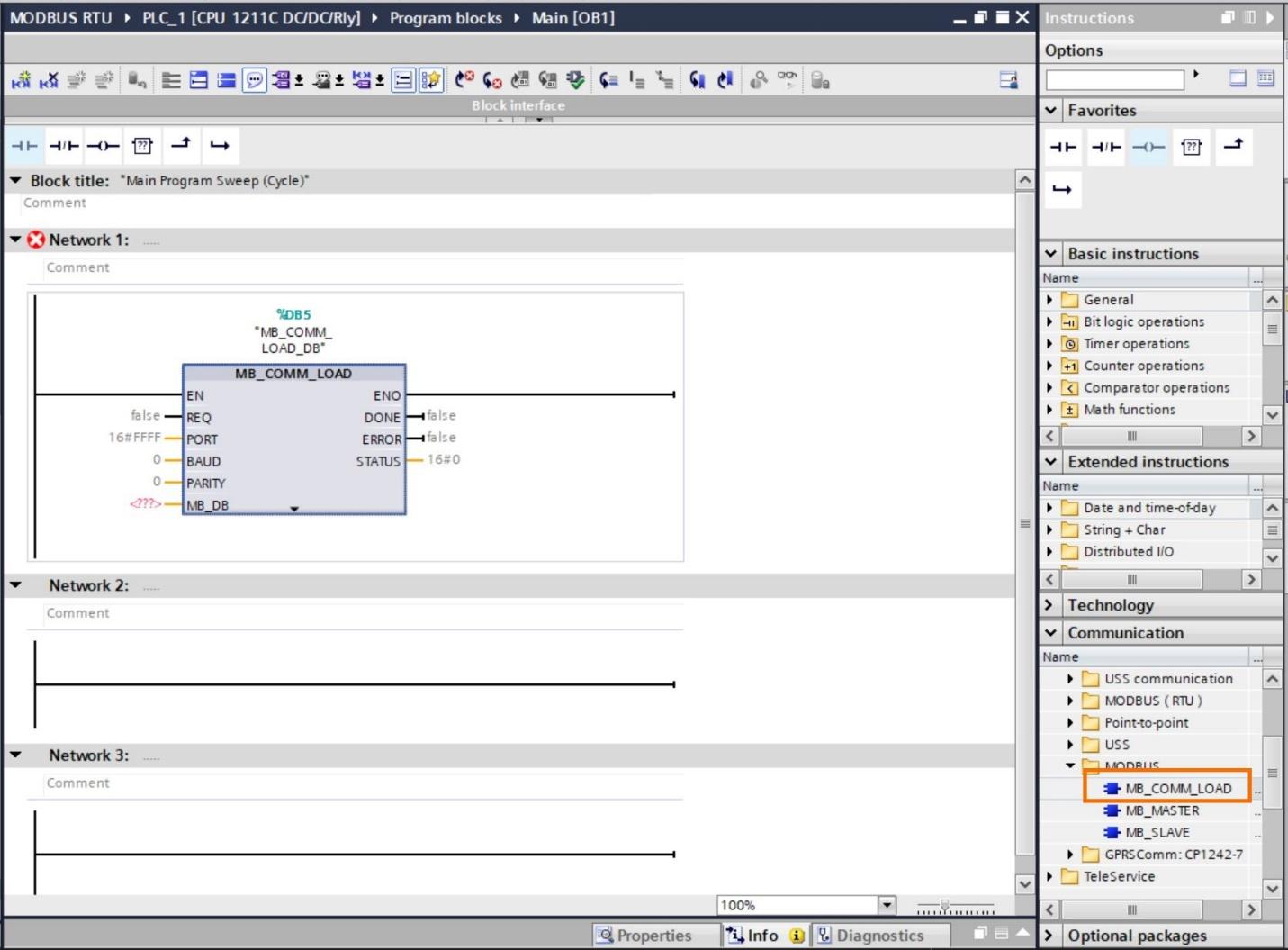
This is a description of the parameters
PORT - ID of the communications port
BAUD - Baud rate selection: 300, 600, 1200, 2400, 4800, 9600, 19200, 38400, 57600, 76800, 115200. All other values are invalid.
PARITY - Parity selection: 0 – None, 1 – Odd, 2 – Even
MB_DB - A reference to the instance data block of the "MB_MASTER" or "MB_SLAVE" instructions. After you insert "MB_SLAVE" or "MB_MASTER" in your program, the DB identifier appears in the drop-down list at the MB_DB box connection.
DONE - Execution of instruction completed without error.
ERROR - Error: 0 – No error detected. 1 – Indicates that an error was detected. An error code is output in the STATUS parameter.
STATUS - Port configuration error code
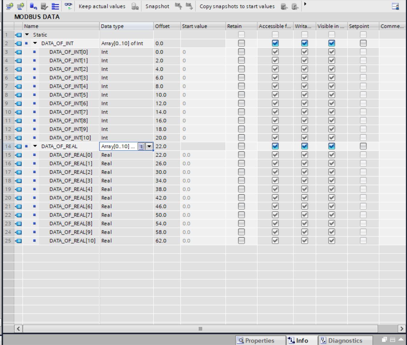
Create a Data block to hold the Modbus data.
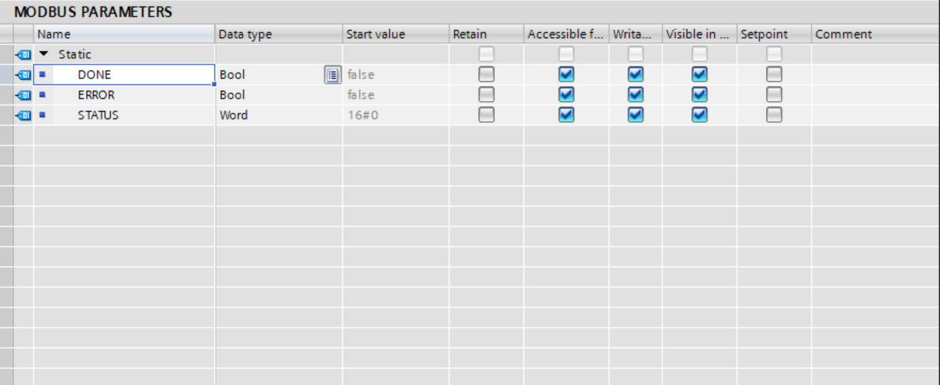
Also, create another data block for the Modbus communication block parameters.
To get the port parameter, clicking the harbinger icon you will see the Local-CB_1241 port number
Configure the block as follows.
Configuring the Modbus Slave
Under communication select Modbus and pick MB_SLAVE. Then configure as follows, compile and download into the PLC.
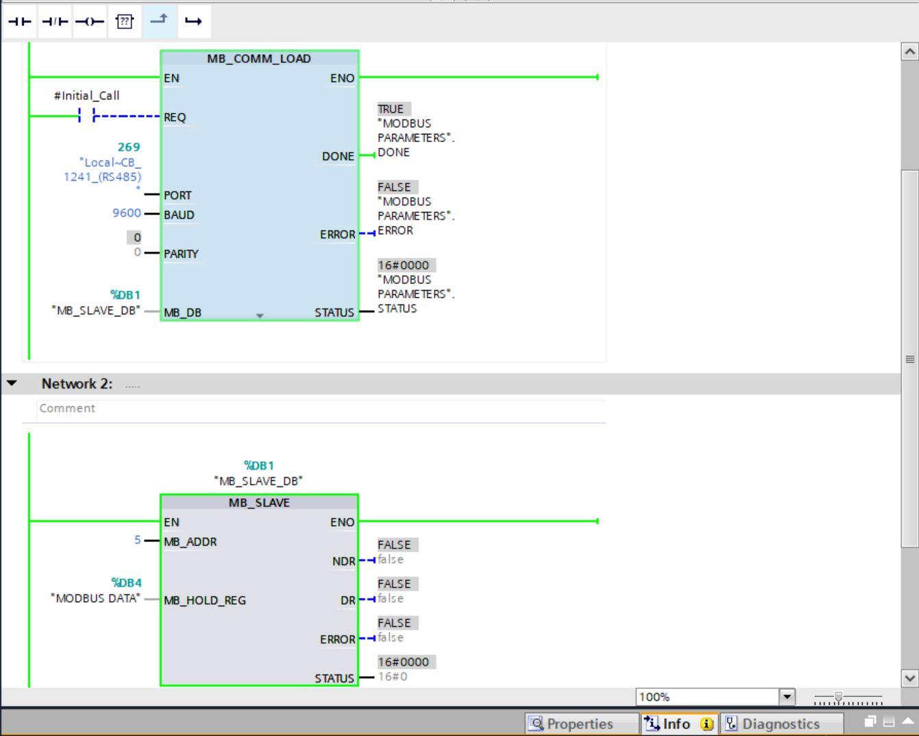
MB_ADDR is the slave ID number of the slave device and we used 5. MB_HOLD is the data block that houses the Modbus data.
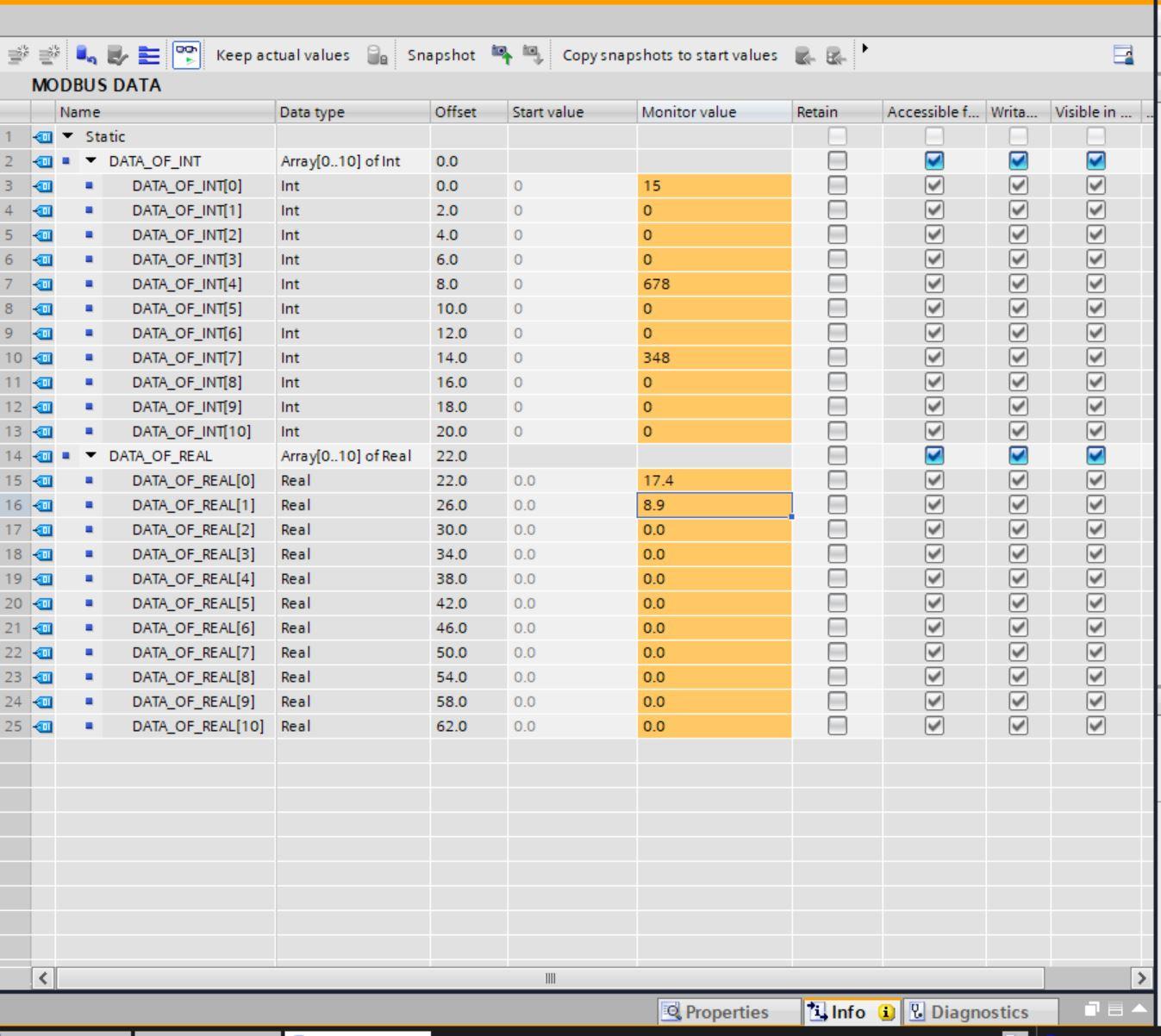
Next input some random data in the Modbus data DB.
Configuring the Modbus Poll
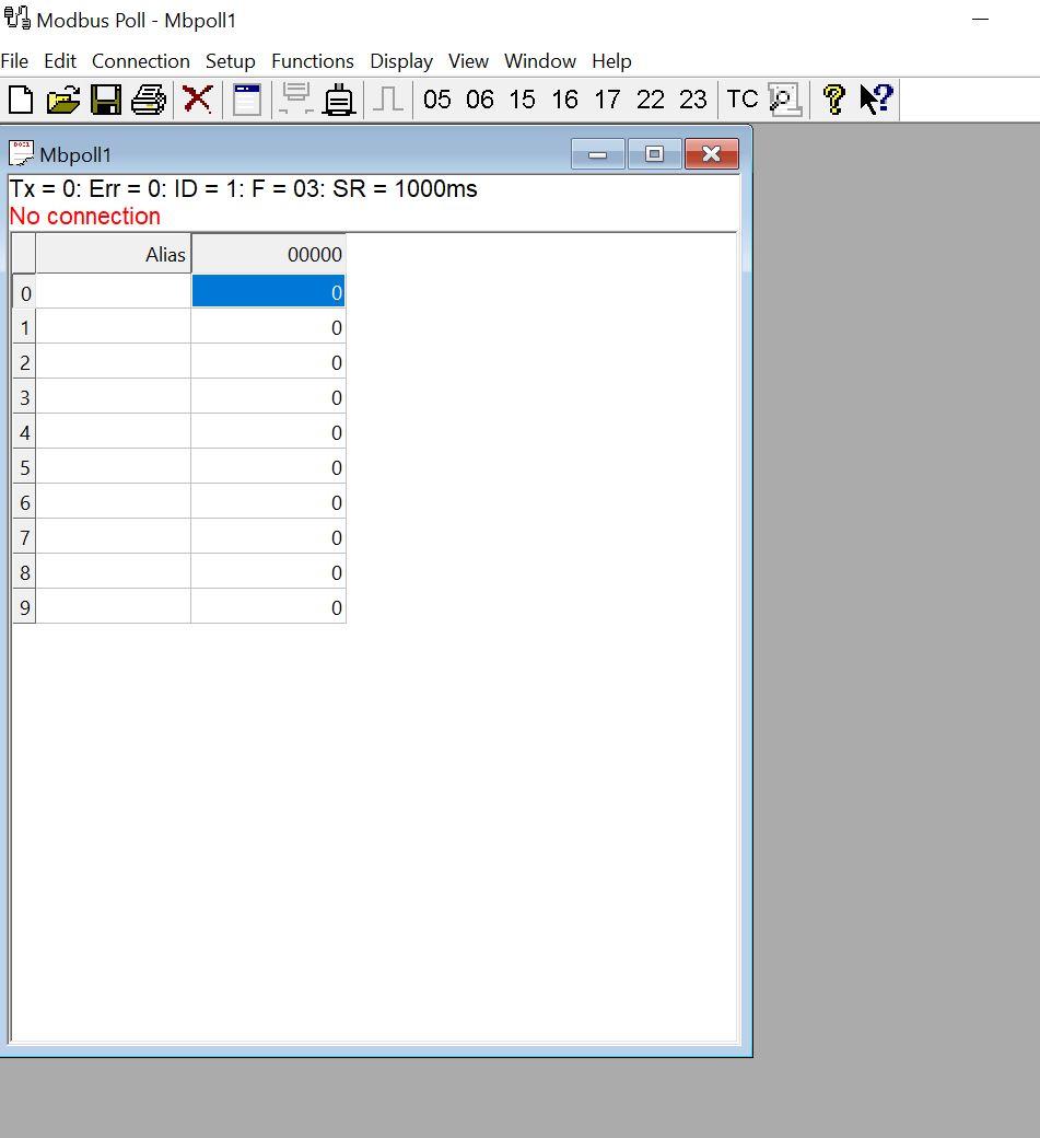
The Modbus poll device is acting as a Modbus device. Launch the Modbus poll software and click on the connection tab.
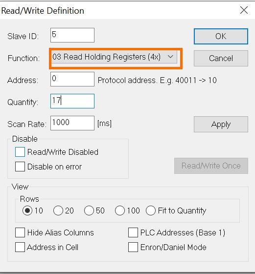
Navigate to setup and select Read/Write definition. Input the right slave ID and quantity. A reminder that the number of readable addresses in the Master device must be less than the slave.
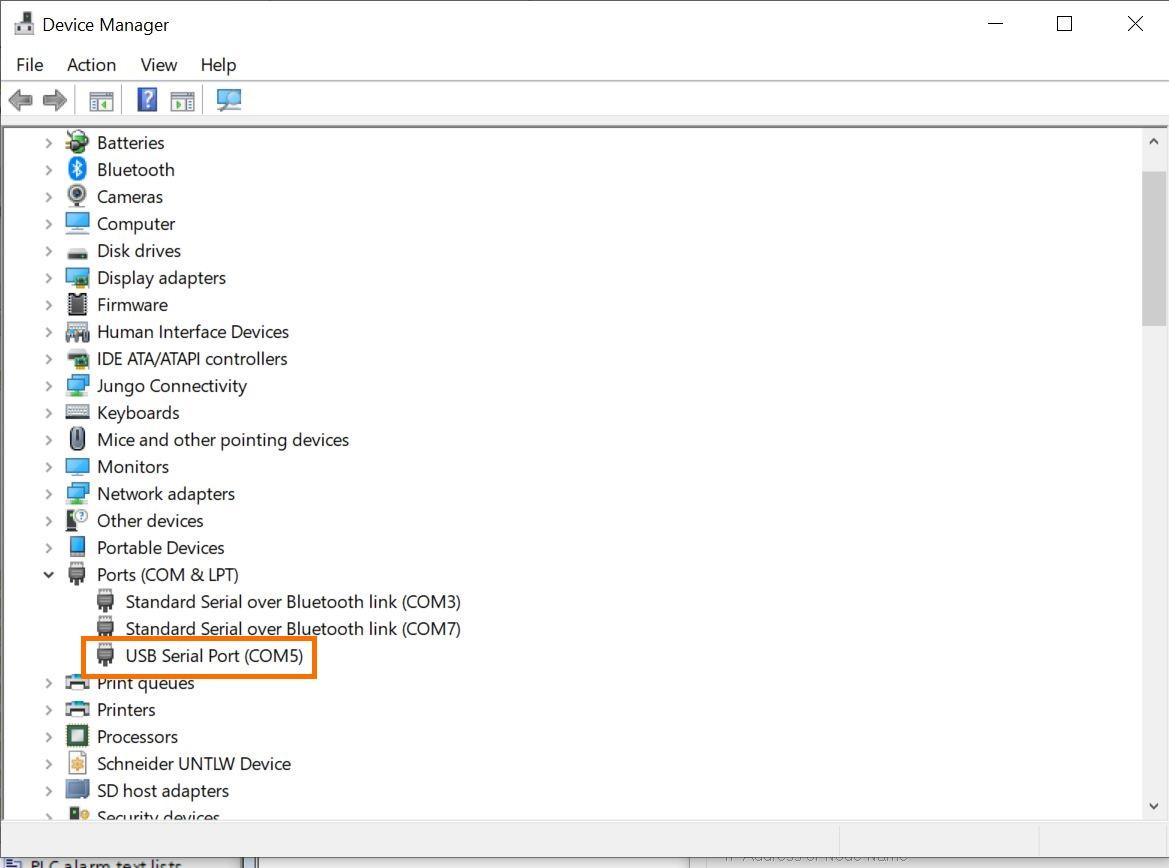
If the device has been connected appropriately checking the device manager under ports will show the connected device. It is serial communication.
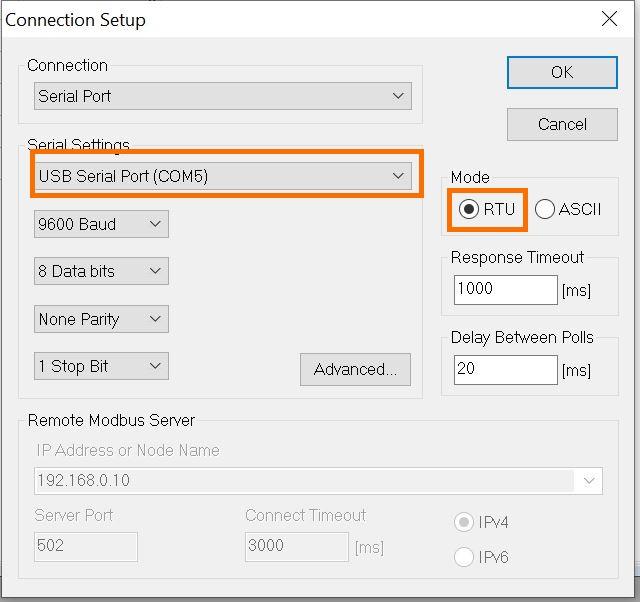
On Modbus Poll connection setup, select the serial communication port, the accurate baud rate as set on TIA Portal then the mode as RTU, and click “OK”.
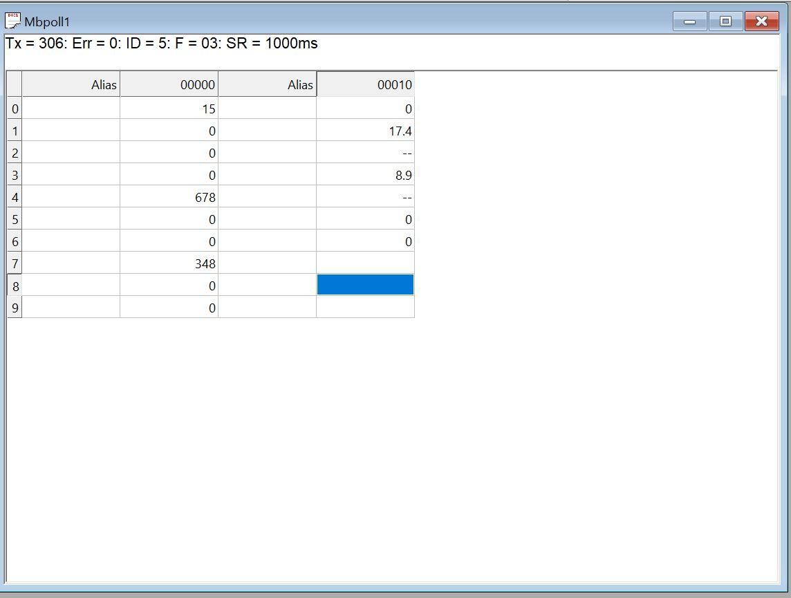
If everything has been done accurately, you will see the data being read from the TIA portal.
To see the floating data, highlight the two registers for the real, for example, the registers showing 16779 and 13107, and right-click to format and select Float AB CD. This will change the format to be seen as a Real data type instead of integers.
Writing Data from Modbus Poll to TIA Portal
Navigate to Setup and select Read/Write definition. Choose to write multiple registers under functions to write data to TIA portal. Thereafter, input some values from Modbus Poll.
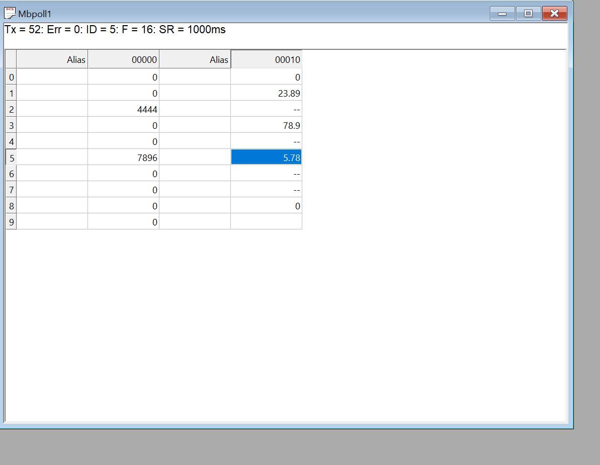
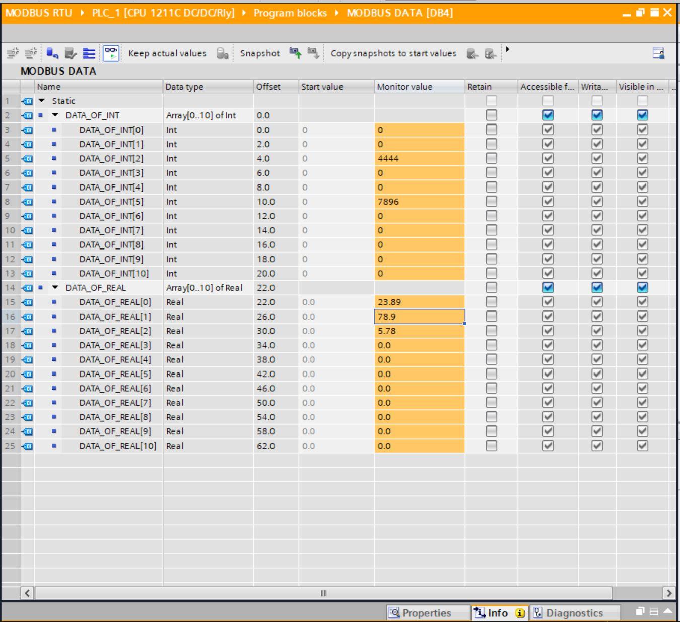
Checking the DB of Modbus data on TIA portal you will see the values from Modbus Poll sitting at the right register locations.
To this point we have successfully read and wrote data from Modbus Poll.
Configuring the Modbus Master
To configure Siemens Modbus Master in TIA Portal, under communications select Modbus and choose MB_Master block.
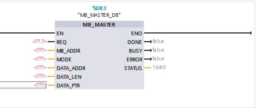
A description of the parameters is given below
MB_ADDR - Modbus RTU station address which is the slave ID.
MODE - Mode selection: Specifies the type of request: Read, write, or diagnostics. 0 means read data while 1 means write data.
DATA_ADDR - Starting address in the slave: This specifies the starting address of the data to be accessed in the Modbus slave.
DATA_LEN - Specifies the number of bits or words to be accessed in this request. This parameter dictates how many registers you intend to read or write to.
DATA_PTR - Points to the DB or bit memory address of the CPU for the data to be written or read. The data block used for holding data is placed here.
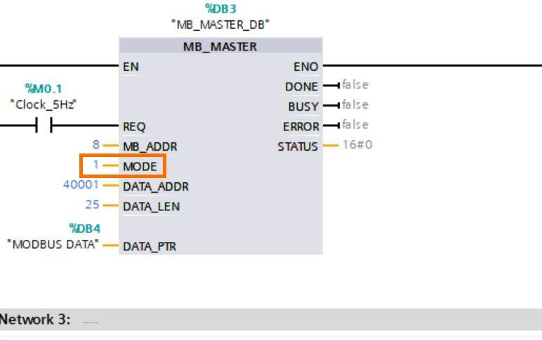
Configure the MB-Master block as shown below and download into the PLC.
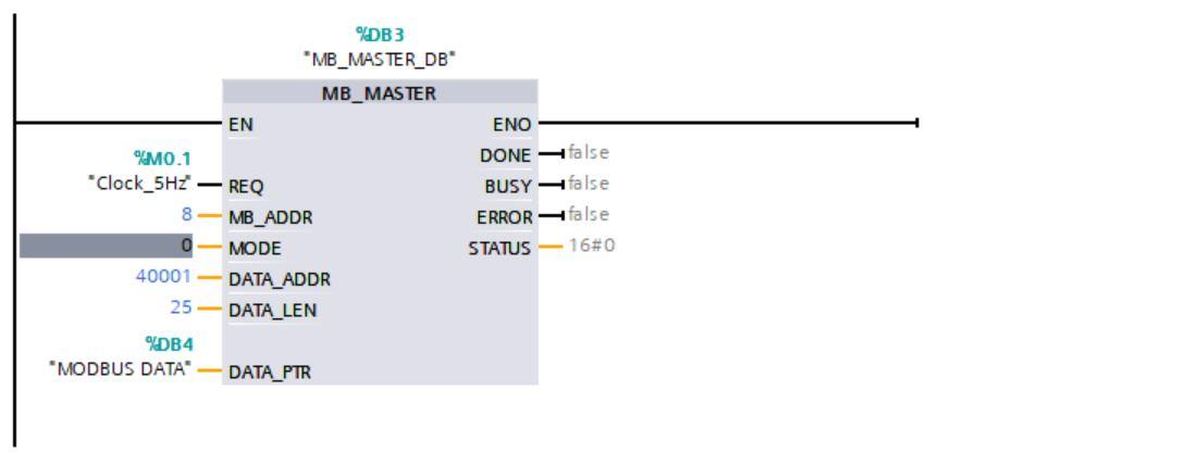
We are using a clock signal as the Request input such that it polls values for every 5Hz scan cycle.
40001 dictates that we are reading from the first holding register.
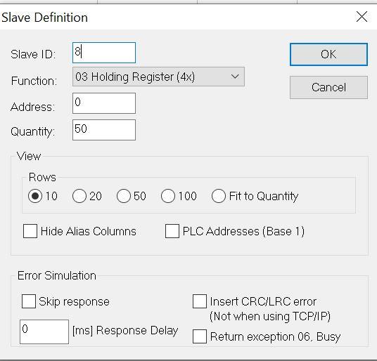
Configuring the Modbus Slave
Launch Modbus slave and setup the slave definitions. The function is Holding register and the slave ID is 8.
For connection settings select the serial port and the COM device and click “OK”. It is the same as the Modbus poll connection settings.
Input some values in the register locations to be sent to TIA Portal.
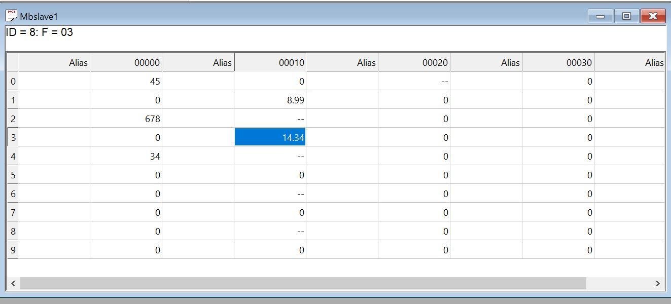
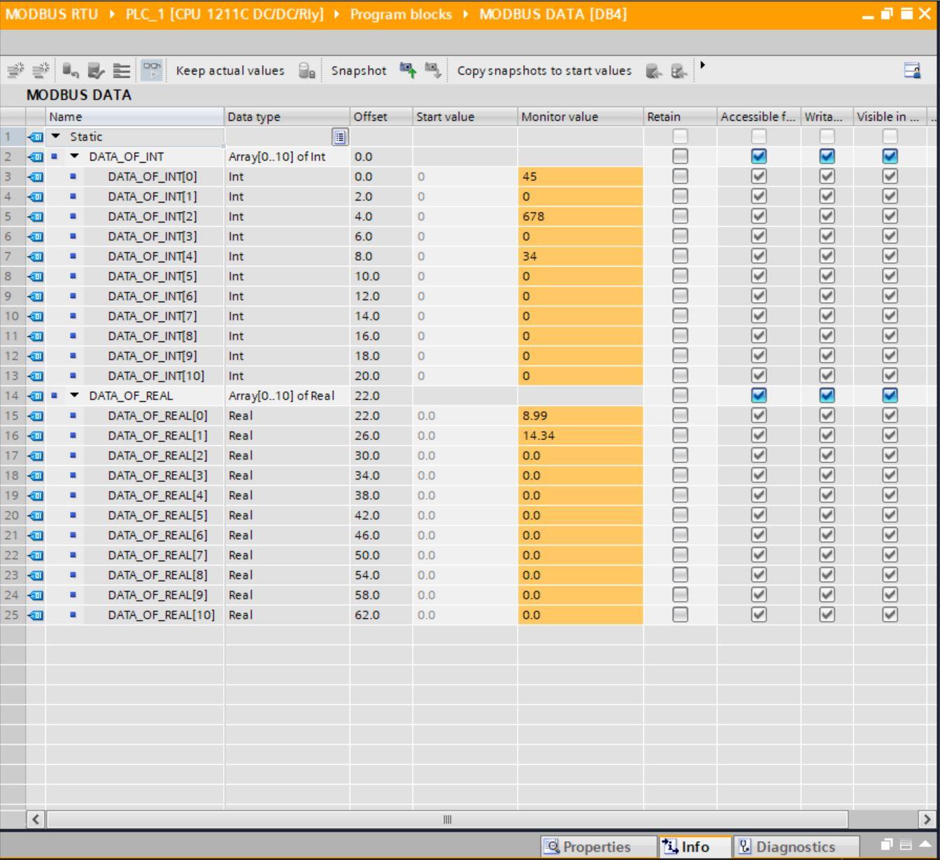
On TIA Portal, checking the DB for Modbus Data shows the data read from Modbus slave
Writing Data from TIA Portal to Modbus Slave
To write data to Modbus slave, the mode on the MB_block will be changed to 1 and the Data Len parameter Increased.
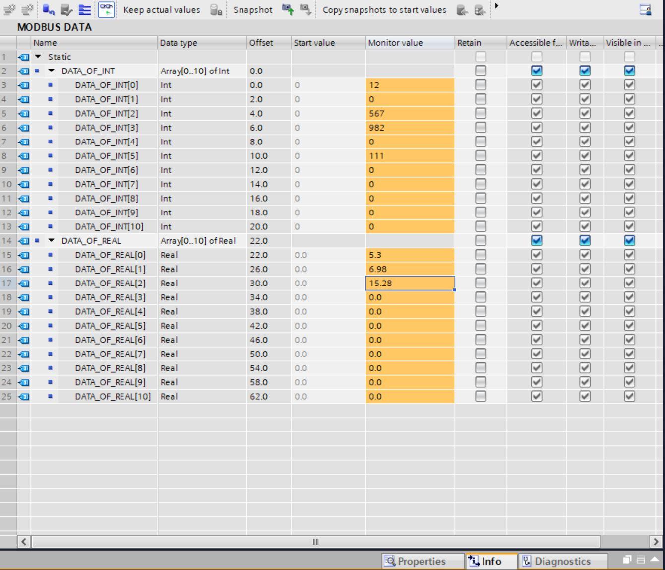
On the Modbus Data block in TIA Portal input some values into the DB addresses. These values will be read from Modbus slave.
Checking the values in Modbus Slave we can see them in the various register locations.
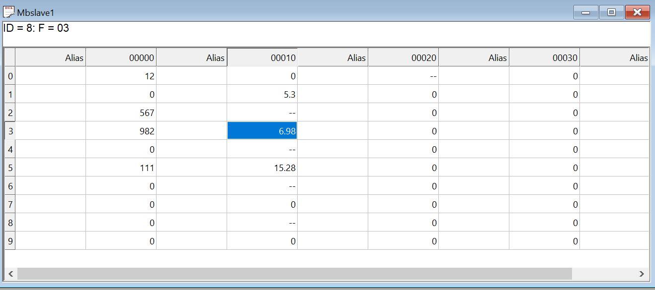
If you can successfully see the data, it therefore means that the Modbus communication between TIA Portal and Modbus Slave is accurate.
Conclusion
Modbus RTU communication is one of the oldest types of Modbus communication, and it is still widely used today, predominantly for SCADA. Most industrial devices and equipment use Modbus RTU as part of their communication protocols since it is helpful in the harshest environments and situations. As a result, as an Automation/Controls specialist, having a solid understanding of it will be beneficial.
