

OPC UA Client Communication in Siemens TIA Portal

Introduction
Getting two PLCs to talk to each other shouldn't require a custom protocol every time. That's the headache OPC UA was built to solve, and now the S7-1500 can act as a client, not just a server, pulling that communication directly into your control logic. If you've ever wrestled with proprietary interfaces or watched a project stall because two systems couldn't agree on a common language, this is worth your time. Machine-to-machine communication built on an open standard means fewer workarounds, less vendor lock-in, and an easier-to-maintain control system. This tutorial shows you how to put that capability to work.
Application Example Overview
SIMATIC S7-1500 controllers running firmware version 2.6 or later include an OPC UA client that becomes part of the overall control system. Thanks to this feature, machine-to-machine communication can now run entirely over OPC UA on a SIMATIC S7-1500 PLC. Programming the OPC UA client is done through system function blocks, while it is not the case for the controller's OPC UA server. Rather than building everything from scratch, this example provides the 'OpcUaClient' block, which wraps the core OPC UA system function blocks and streamlines both implementation and programming. For this example, an S7-1500 controller with a basic process-value simulation program serves as the OPC UA server. You're free to swap in any other OPC UA server instead. 'Registered Read', 'Registered Write', and 'Registered Method Call' are the three access types that both the OPC UA client and its user block are built to support.
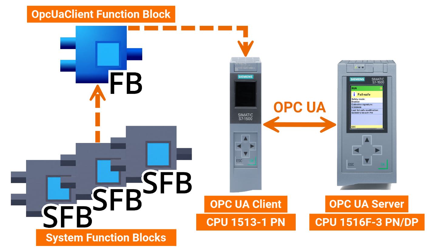
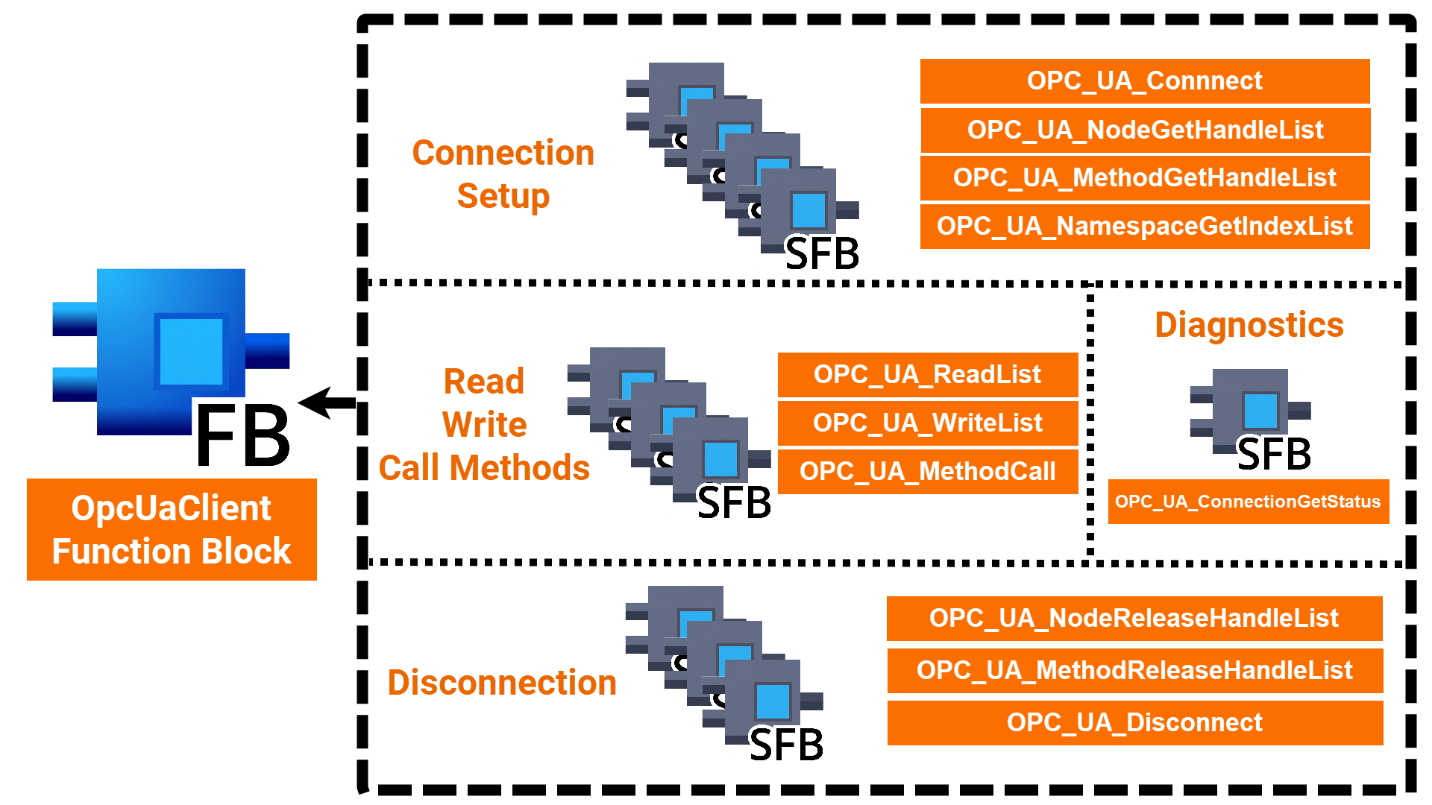
Making the OPC UA Client work means calling, configuring, and evaluating a handful of system function blocks (as shown in Figure 1.2) within the 'OpcUaClient' user block, grouped by purpose.
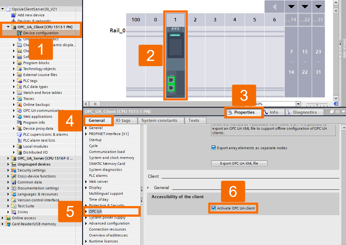
Activating OPC UA Client
Getting the OPC UA ready starts with three steps: enabling the OPC UA Client, setting up an OPC UA Client Interface, and configuring the OPC UA block. You first have to enable the client in the CPU's properties before its OPC UA functions are usable. Open the 'Device Configuration' of your CPU by navigating through the TIA Portal project tree. Head to 'OPC UA -> Client -> General' in the Inspector window and check the box labeled 'Activate OPC UA Client'.
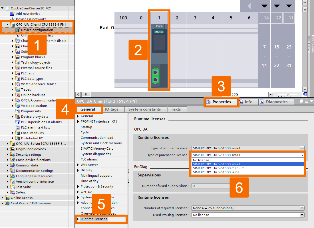
Next, double-check that the necessary OPC UA license is in place. In 'Runtime Licenses', locate the OPC UA category and select the license that applies.
Setting Up OPC UA Client Interface
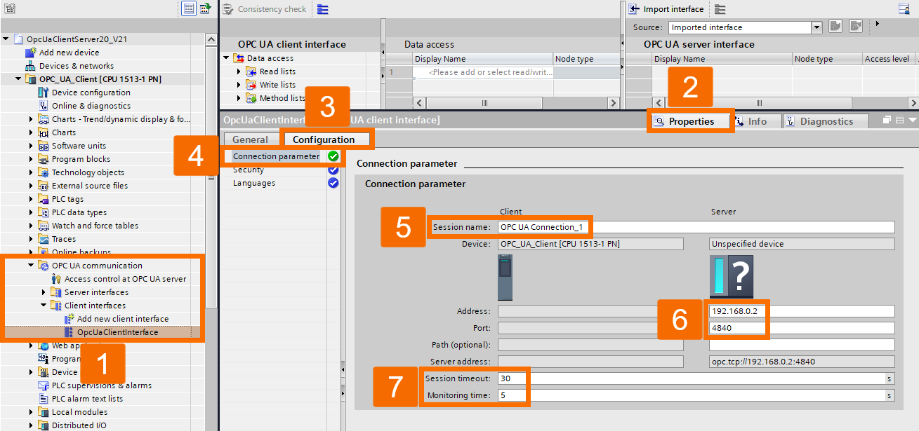
You'll need to set up a client interface before the OPC UA functions of the system function blocks can be used. All the data required by the 'OpcUaClient' client module is stored within this interface. First, the connection information needs to be configured. To do so, locate 'OPC UA Communication -> Client Interfaces' in the TIA Portal project tree, then double-click on the 'Add New Client Interface' to continue. Provide a session name and the server's 'Address' and 'Port' values inside 'Properties -> Configuration -> Connection Parameters' within the inspector window. Choose an appropriate 'Session Timeout' and whatever 'Monitoring Time' suits your needs.
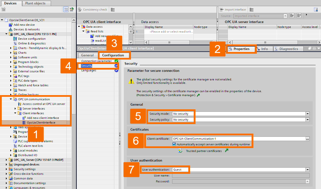
Choose your required 'Security policy' and 'Security mode' from the inspector window's 'Properties -> Configuration -> Security' section that applies to your project. Should you want the connection encrypted or signed, define a 'Client Certificate' and set up the 'User Authentication' that's needed.
Configuring Lists
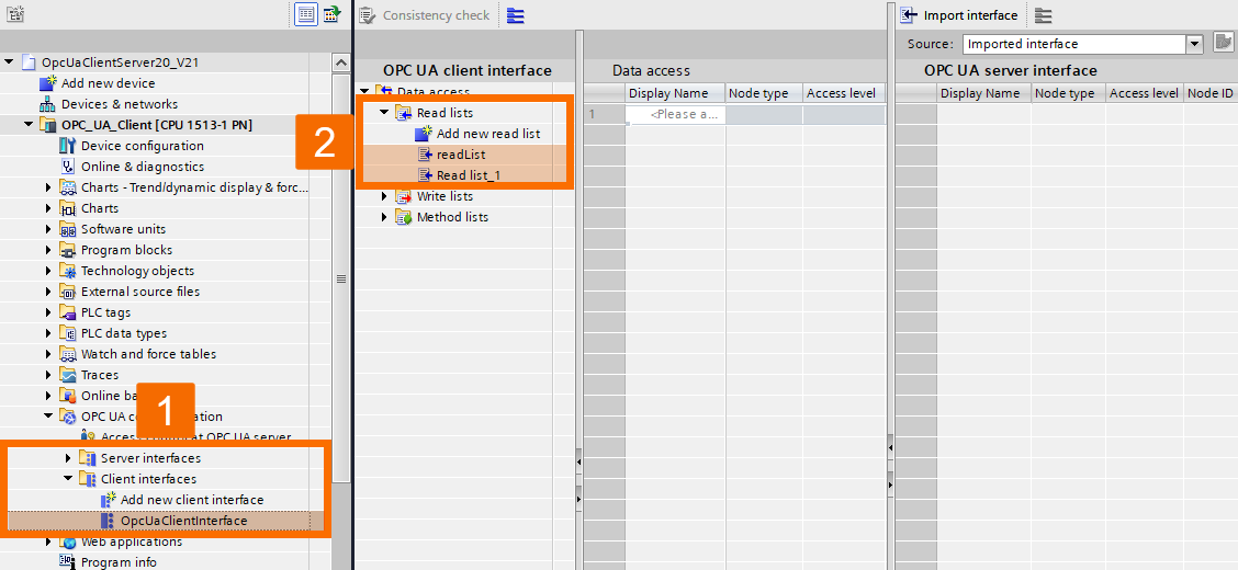
It's time to set up the lists. Find 'Data access -> Read lists' in the left pane of the workspace and double-click on 'Add New' for a fresh read list.
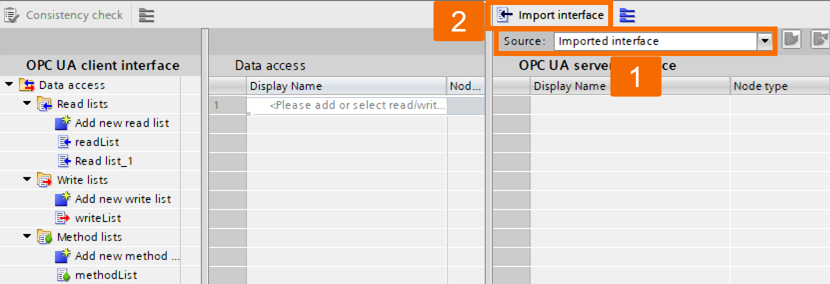
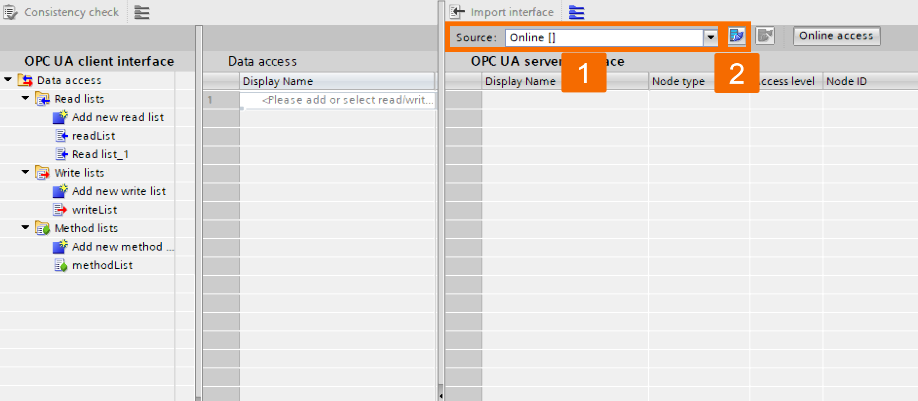
At this point, you've got two choices for populating the reading list. Choose between connecting directly to a server online or importing a server interface XML file. On the workspace's right side, choose your option from the 'Source of Server Data' drop-down list.
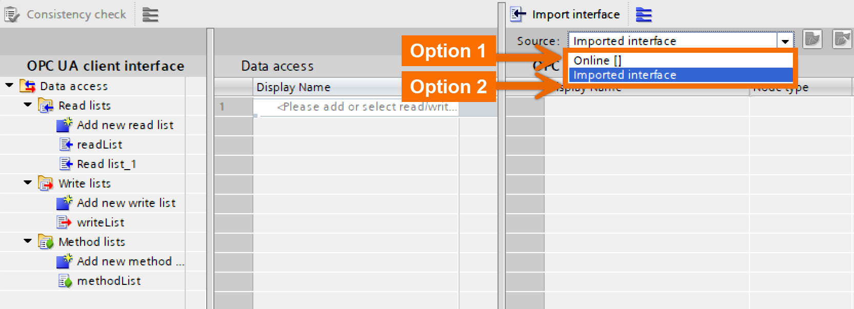
For the 'Imported Interface' option, left-click on the Import button to proceed. In the dialog window, browse to your server interface's XML file, choose it, and verify using 'Import'.
If the 'Online' option is your solution, click the 'Connect to Online Server' button.
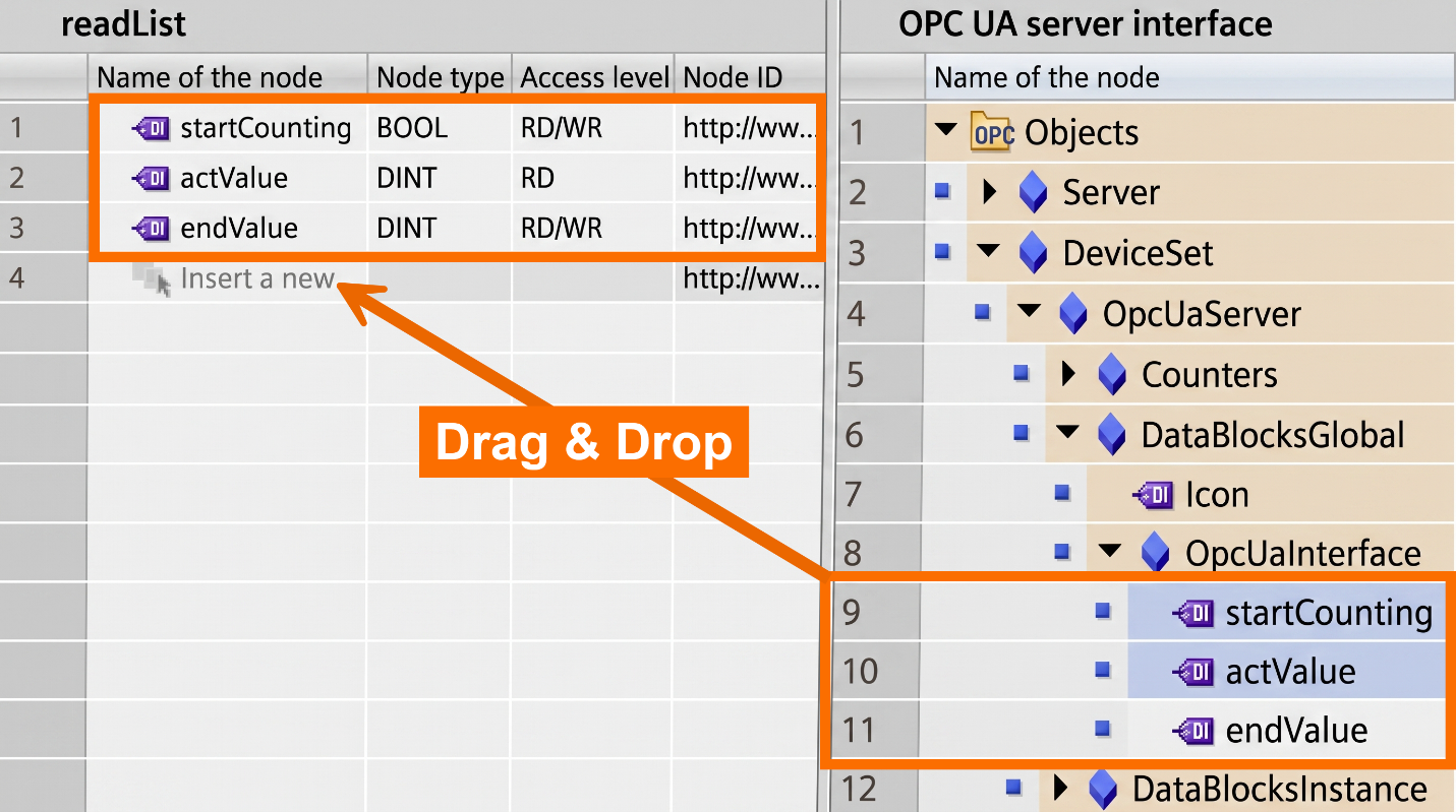
Move the server interface variables you plan to read by dragging and dropping them into the read list.
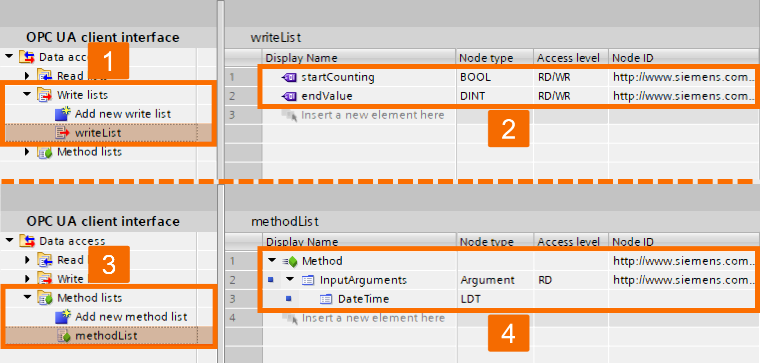
Follow the same procedure once more for the Write and Method lists.
From the project tree, select the CPU and hit the 'Compile' button. Once compiled, TIA Portal builds the 'Configuration' and 'Data' data blocks, which carry all the OPC UA transfer parameters for the 'OpcUaClient' user block. Whenever you modify the OPC UA-Client interface, compile the CPU again afterward so the updated parameters get carried over into the data blocks.
Configuring OPC UA Client Block
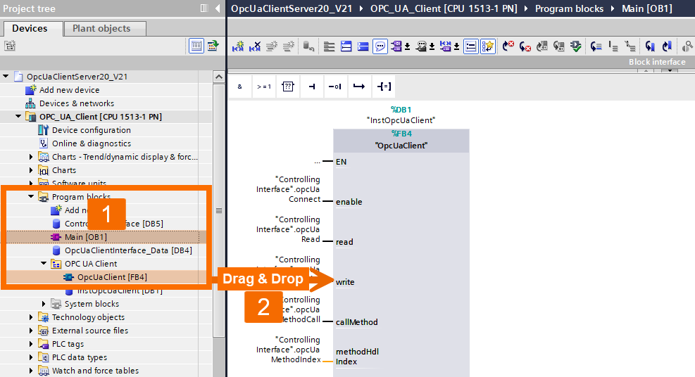
Head to 'OpcUaClient -> Program Blocks -> OPC UA Client' in the project tree and drag and drop the 'OpcUaClient' block, downloadable from here, into your network programming. The 'OpcUaClient' block interface requires its parameters to be configured inside the user program. Inside a cyclic OB, call the block and create a fresh new instance for it.
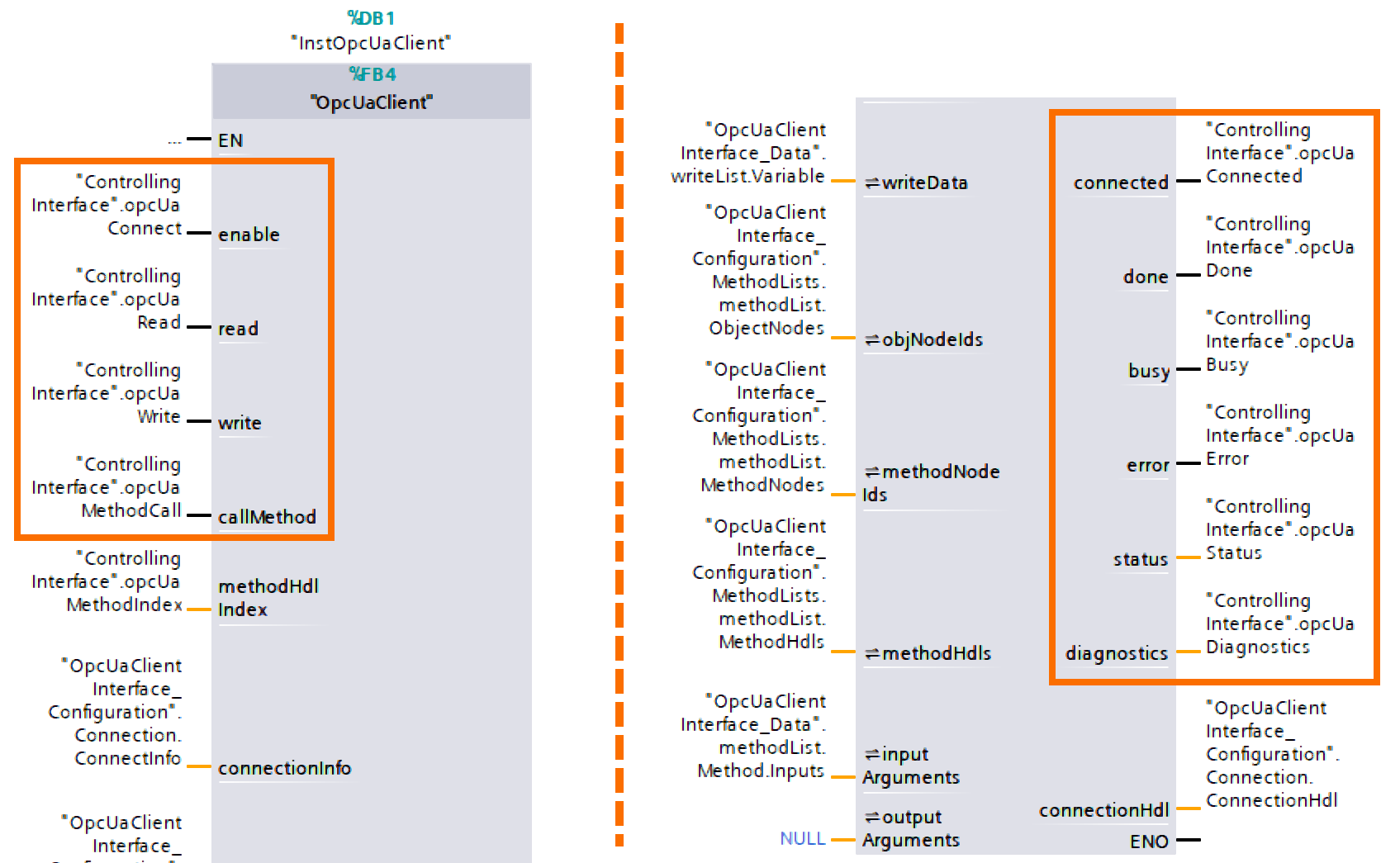
The block's control and diagnosis parameters need to be connected. Set up appropriate variables for this purpose.
Hook up the parameters belonging to the 'OpcUaClient' block's client interface. The data blocks created through the client interface hold the variables that require interconnecting.
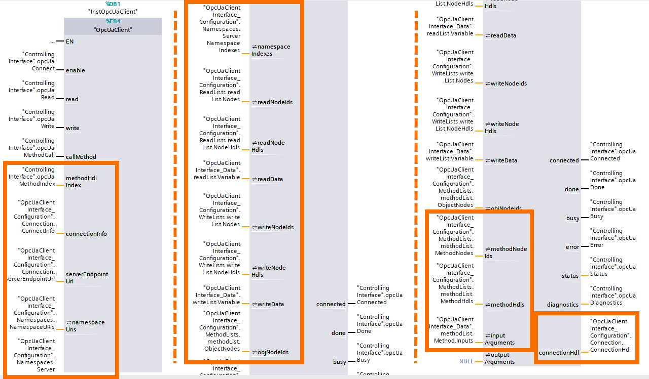
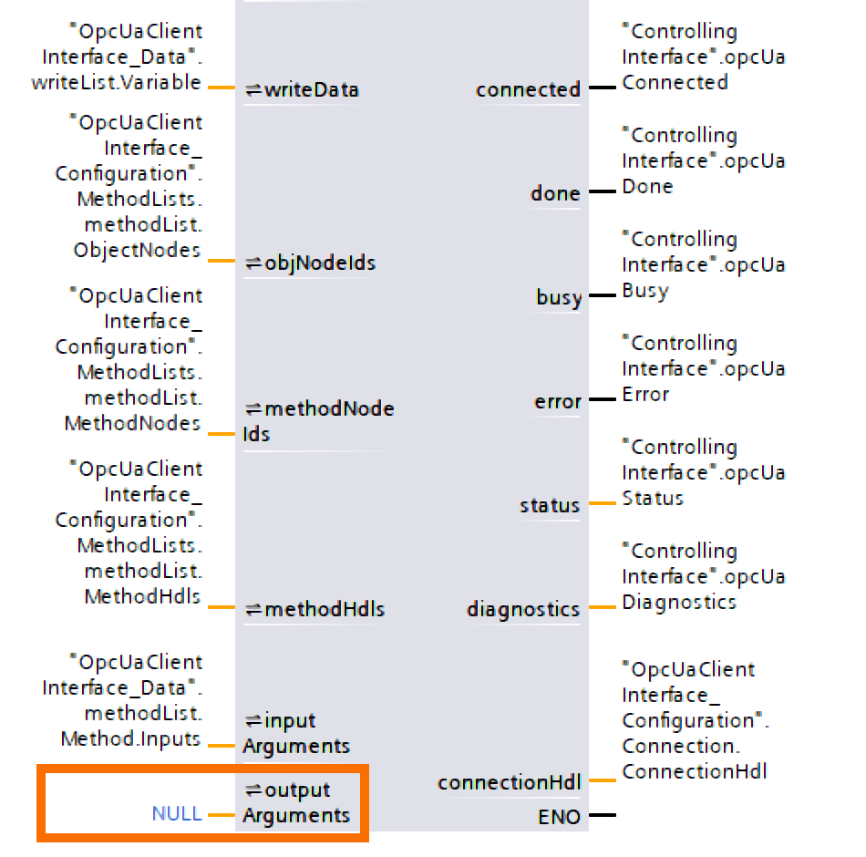
Give 'NULL' to the blocks that aren't required. The 'Connection' block's parameters cannot be left out.
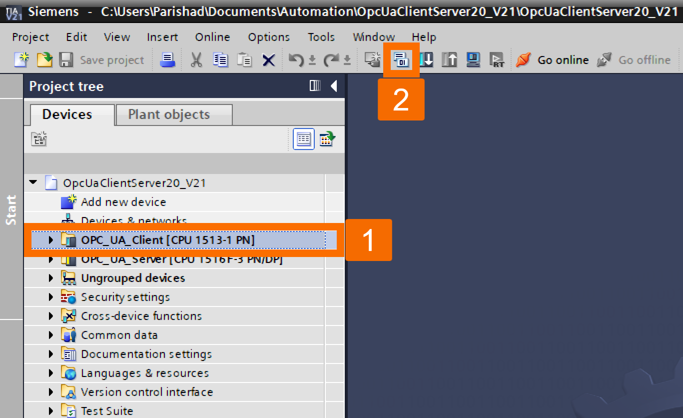
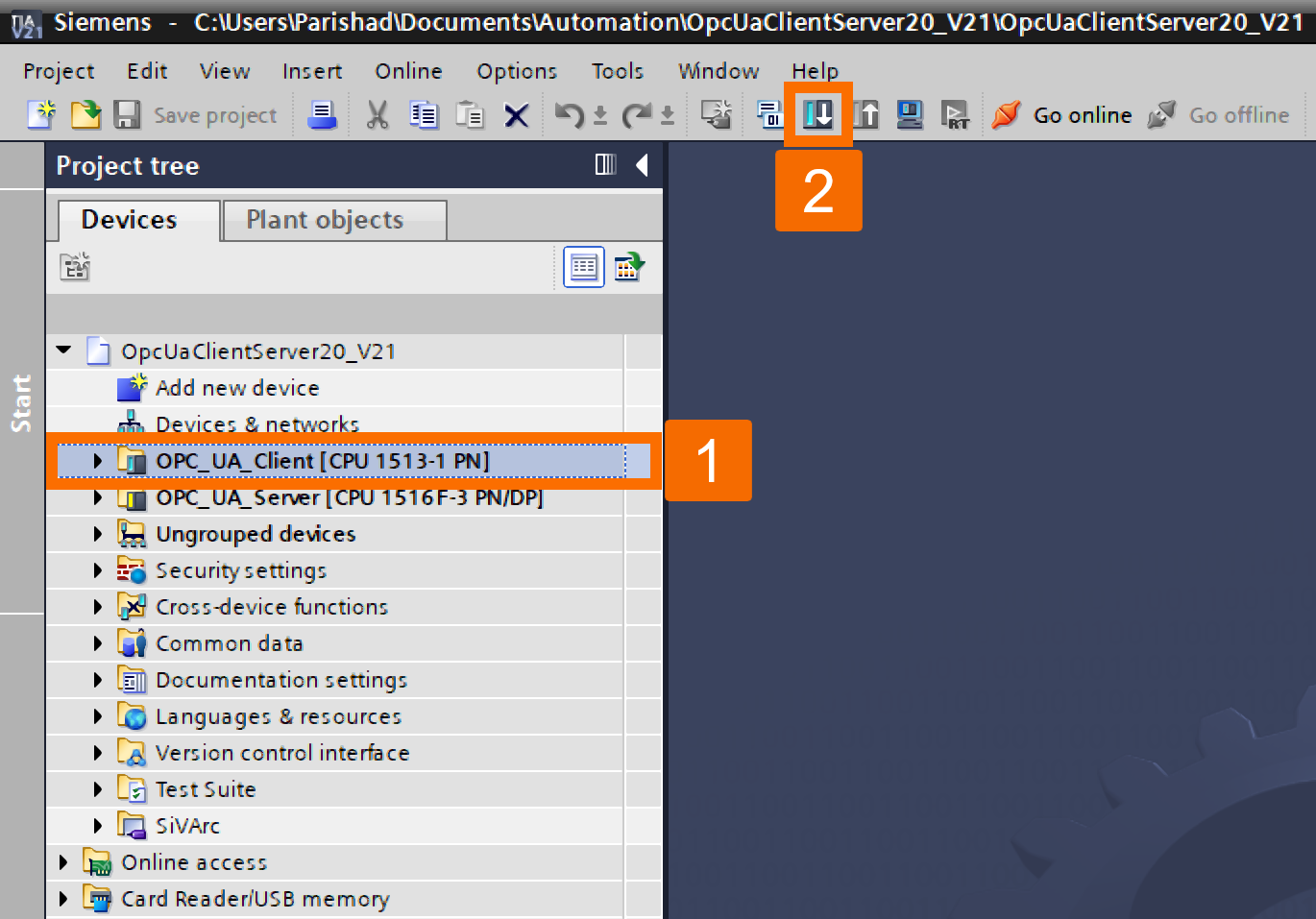
In the project tree, choose the CPU. Then click the 'Download to Device' button on the top toolbar so the project transfers onto the PLC.
Application Example Operation
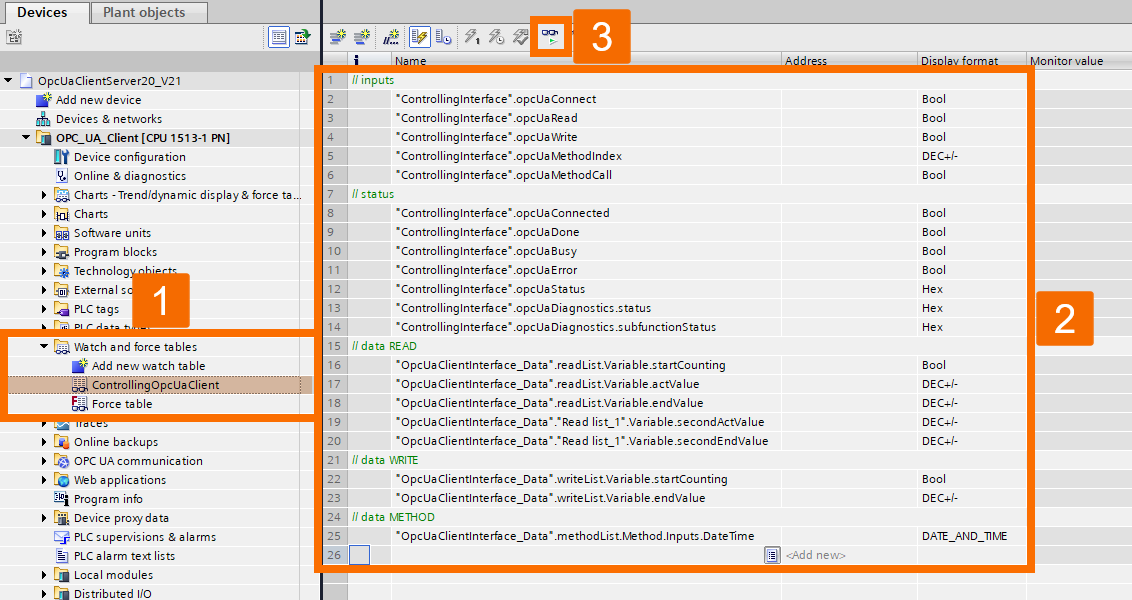
Browse to 'OpcUaClient -> Watch and Force Tables' in the project tree and double-click the 'ControllingOpcUaClient' watch table to open it. Live values for the controller's variables will be displayed once you click the 'Monitor All' icon in the workspace toolbar.
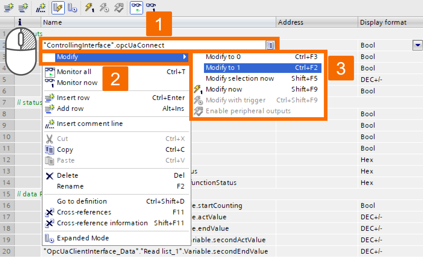
The connection between your client and the server begins when you switch the 'opcUaConnect variable in the 'Inputs' section to 'TRUE'. This is done by right-clicking the variable and picking 'Modify > Modify to 1' from the menu.
Verify the connection by monitoring the 'opcUaConnected' variable under the 'Outputs' section. The 'TRUE' value indicates the client is connected, and the 'FALSE' value indicates it is disconnected.

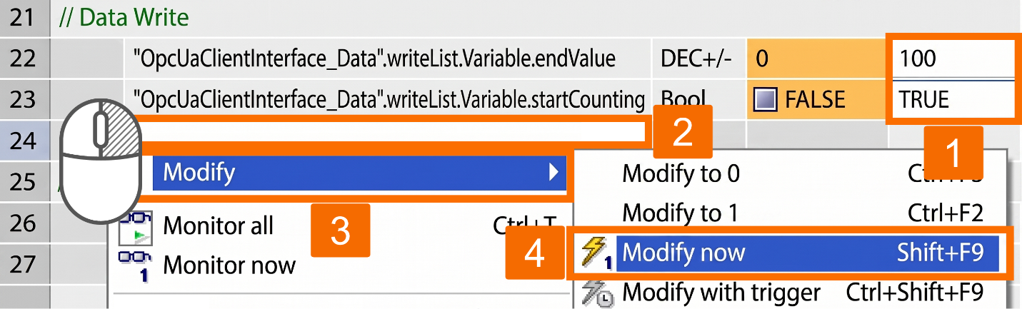
Once connected to the OPC UA server, the client can read variables from it, write variables into it, or call methods on it. It's time to learn how writing variables works. The variables inside the 'Data Write' section are what you'll control. Fill in your desired write values under the 'Modify Value' column. You can set the upper counting limit for the OPC UA server's counter using the 'endValue' variable, which is set to 100 in this example. Whether the counter is active on the server depends on 'startCounting', which is set to 'TRUE' in this case. Get the values onto the controller by right-clicking the workspace and selecting 'Modify -> Modify Now'.
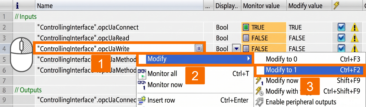
Setting the 'OpcUaWrite' variable in the 'Inputs' section to 'TRUE' is how you write the OPC UA variables to the server. Make this happen by right-clicking the variable and picking 'Modify -> Modify to 1'.
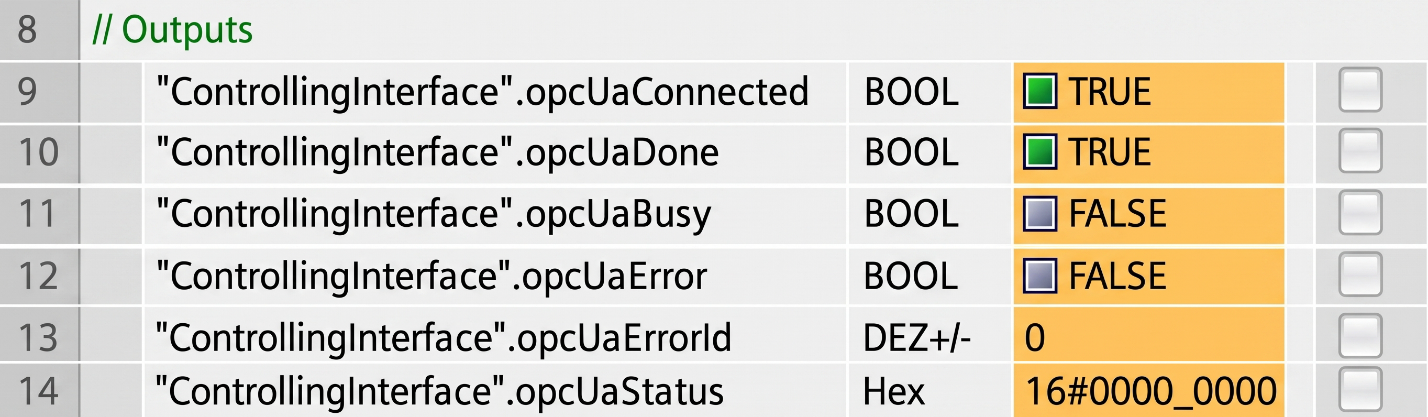
Verify that the write job went through. The 'Outputs' section holds 'opcUaDone', 'opcUaErrorId', 'opcUaError', and 'opcUaStatus', which you should monitor.
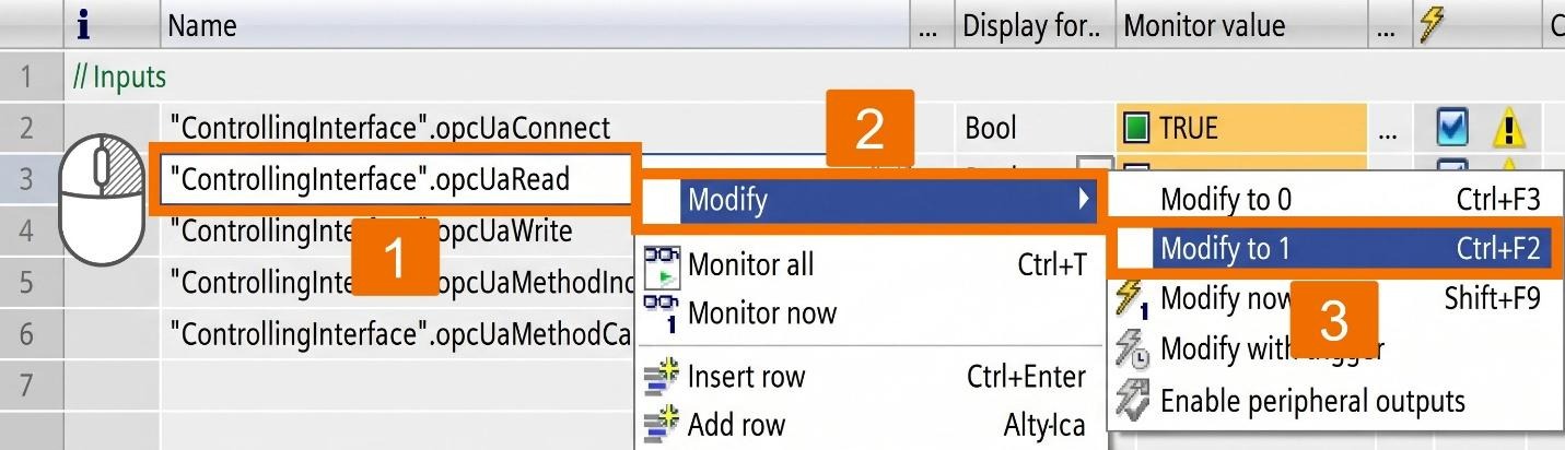
It's time to read the server's variables. Setting the 'OpcUaRead' variable to 'TRUE' under the 'Inputs' section is how you trigger a read of the server's OPC UA variables. To make this happen, right-click the variable and pick 'Modify > Modify to 1'.
Confirm that the read request succeeded. In the 'Outputs' section, keep track of the 'opcUaDone', 'opcUaErrorId', "opcUaError", and 'opcUaStatus' variables.
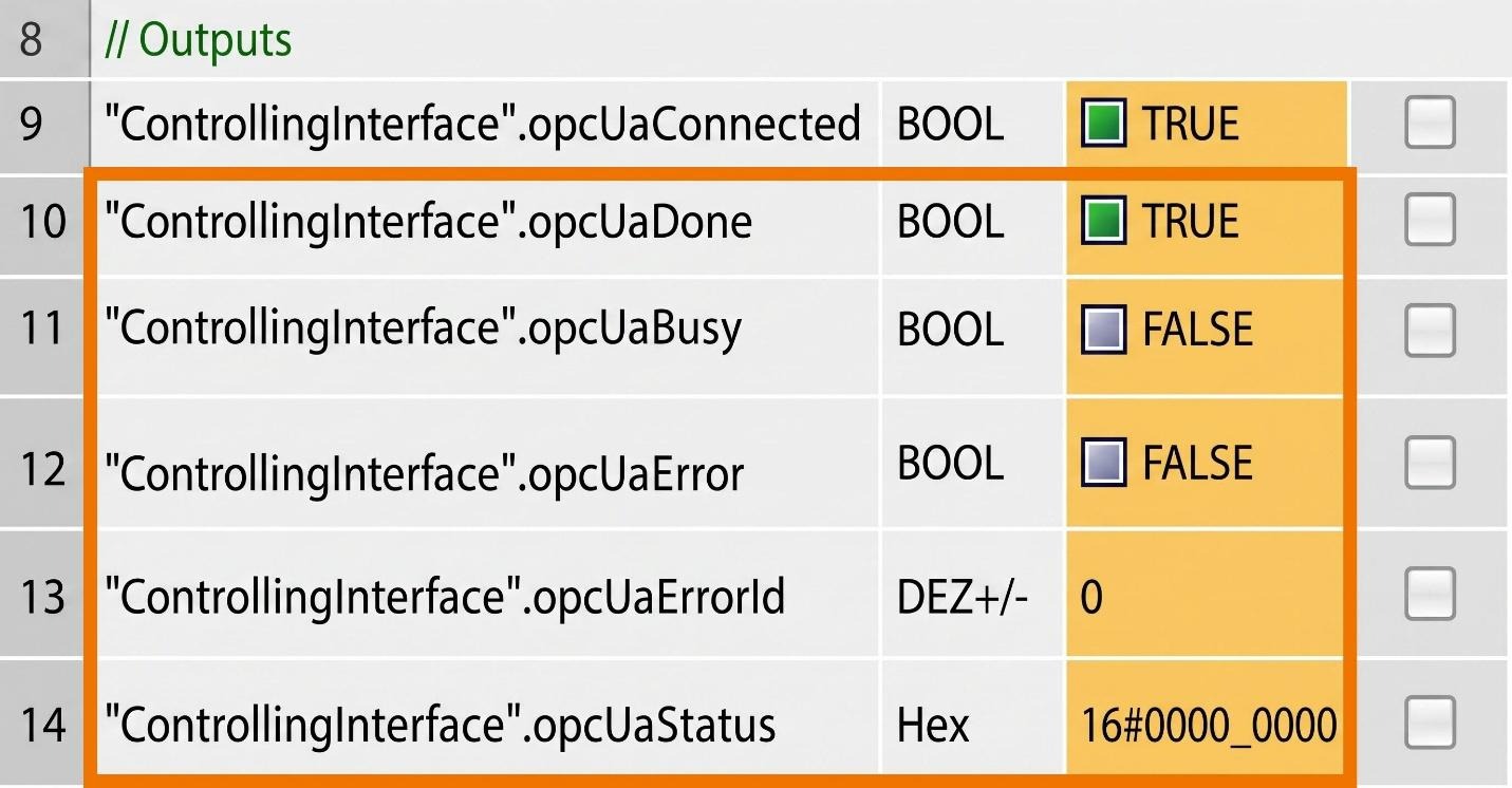
Watch what appears in the 'Data Read' section. If 'endValue' was set beforehand and 'startCounting' is on, then 'actValue' will keep changing every second. More read requests will let you confirm the value is changing.

Finally, learn how to call the OPC UA method on the server. The 'dataTime' variable, located in the 'Data Method' section, is what you'll control. Fill in the 'Modify Value' column with the PLC time to transfer. To push the value onto the controller, right-click the workspace and pick 'Modify -> Modify Now'.

Setting 'OpcUaMethodCall' in 'Inputs' to 'TRUE' is the way to trigger the server'sOPC UA method. This is done by right-clicking on the variable and picking 'Modify > Modify to 1'.
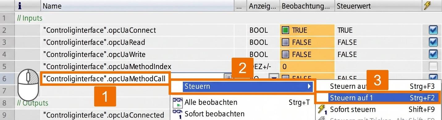
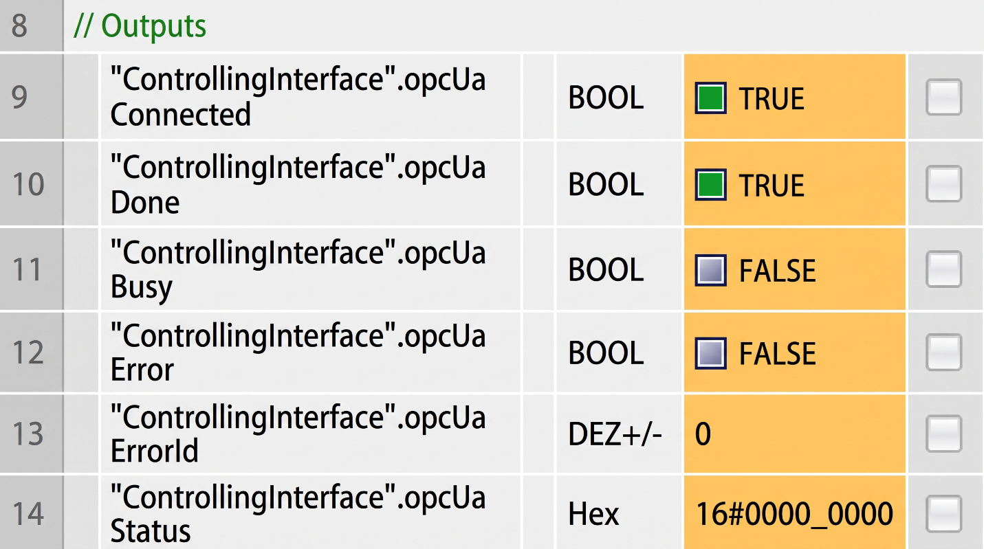
Confirm the method call worked, then under 'Outputs', check 'opcUaDone', 'opcUaErrorId', 'opcUaError', and 'opcUaStatus' variables. Verify that the PLC time has updated on your server CPU's display.
Conclusion
In conclusion, you have learned how to activate the OPC UA client on an S7-1500 CPU and configure a client interface with the correct connection, security, and authentication settings. You've also seen how to build read, write, and method lists, compile them into usable data blocks, and wire those parameters into the 'OpcUaClient' block within your program. From there, you tested the connection using a watch table, confirmed data exchange by reading and writing variables, and triggered a method call on the server. With this foundation, you're ready to adapt the setup to your own OPC UA server and expand your project's machine-to-machine communication.


