PLC Programming Using Schneider Electric’s Machine Expert

Introduction
Schneider Electric's Machine Expert is a powerful software suite designed for automation engineers, enabling them to efficiently develop and manage control systems. It is an integrated environment for creating and maintaining PLC programs, HMIs, and other automation-related tasks. Our focus will be on PLC programming using the ladder language within Machine Expert. Specifically, we will guide you through the process of creating a simple motor control application, a fundamental aspect of industrial automation.
In this tutorial, you will learn how to set up a new project in Machine Expert, select the appropriate controller model, and program it for your application. We will guide you through the initial steps of creating a Function Block in ladder language to control a motor. Then, we will define global variables using a GVL and map them to digital inputs and outputs. We will conclude by demonstrating how Function Block calls are performed within programs and tasks to make the program executed.
Prerequisites
To follow along with this tutorial, you will need an installation of Schneider Electric's Machine Expert.
Also, we advise you to first go through the Machine Expert introduction tutorial to have a complete understanding of all the subjects covered in this tutorial.
Project setup
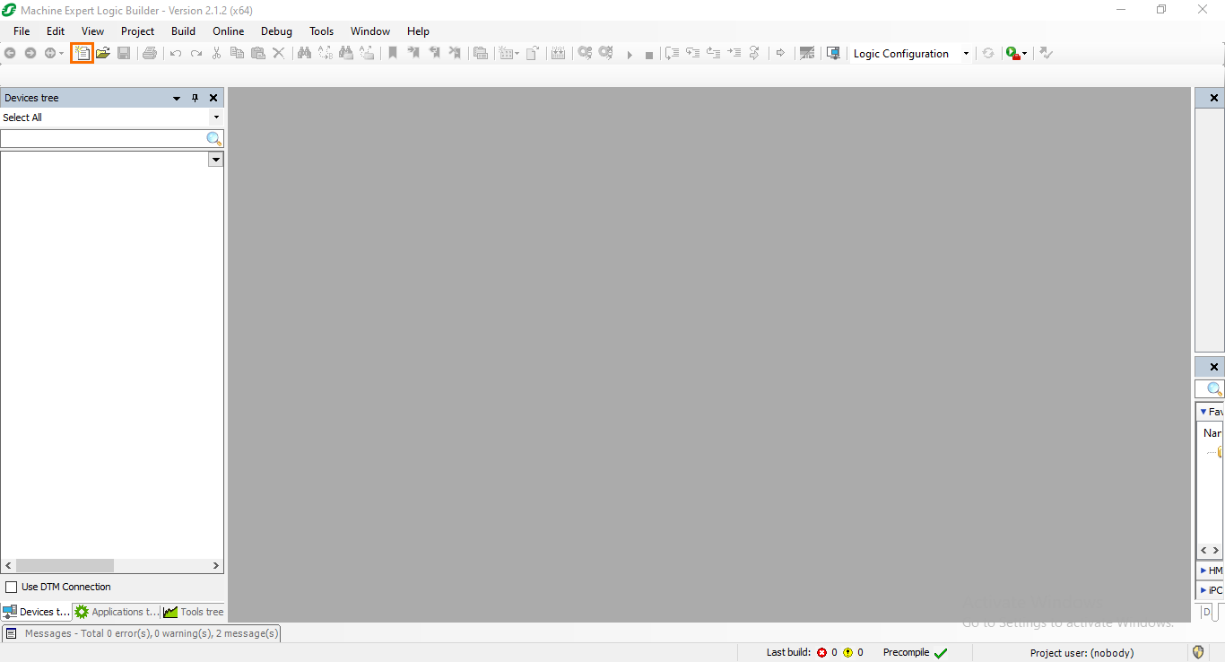
Let’s start by creating a new project. After opening Machine Expert, click on the “New project” button.
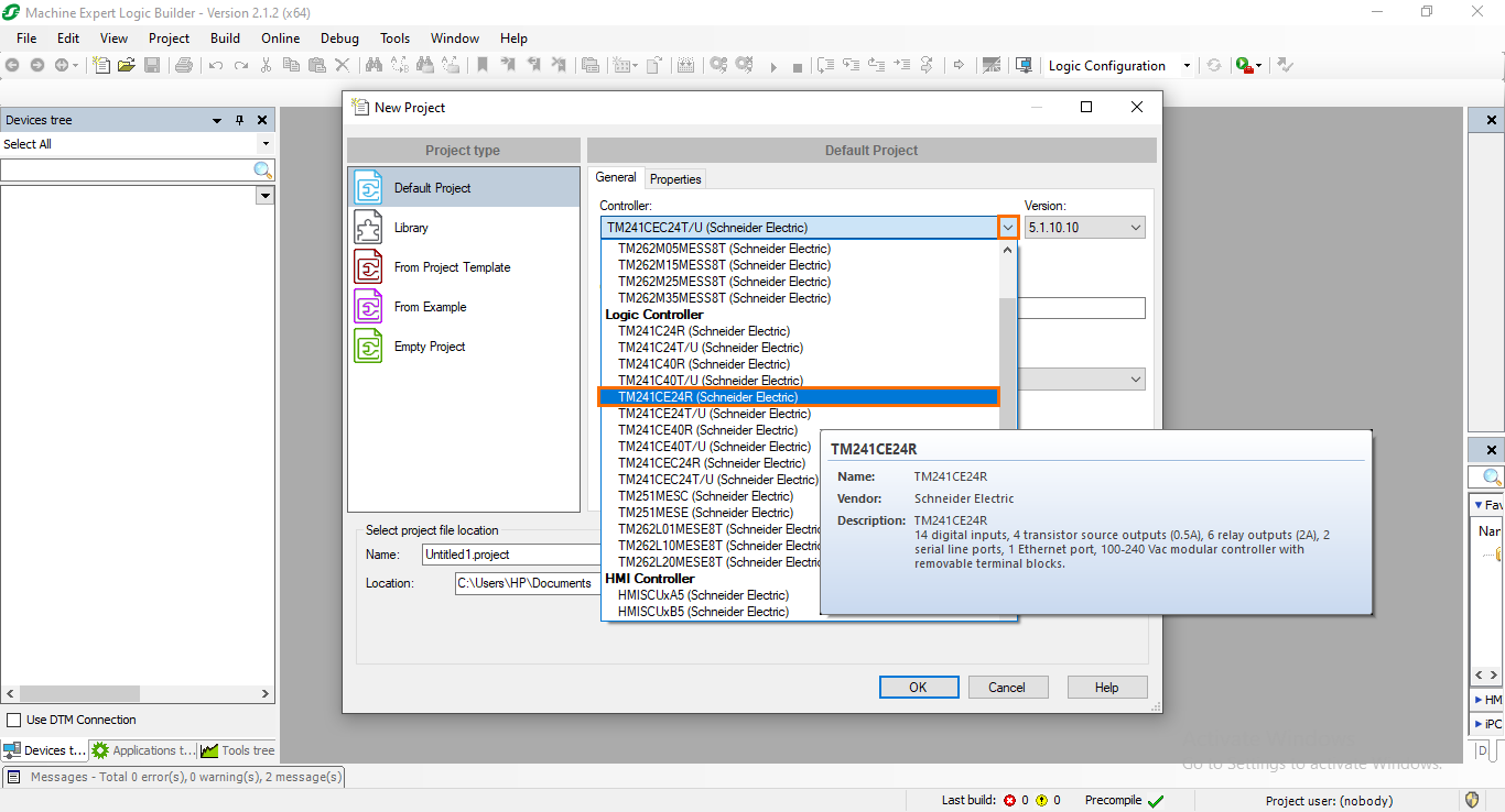
After that, in the project creation window, open the controllers' list and select the TM241CE24R model. This controller has built-in DIs/DQs, allowing us to skip the step of adding modules.
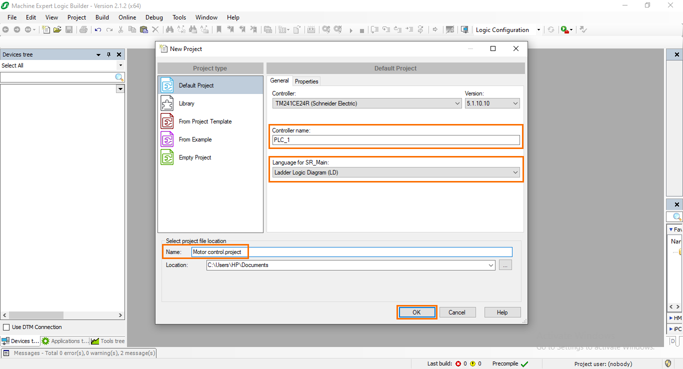
Once done, give a name to the controller and the project. Then, be sure to have “Ladder” selected as your default programming language. Complete by clicking on “OK.”
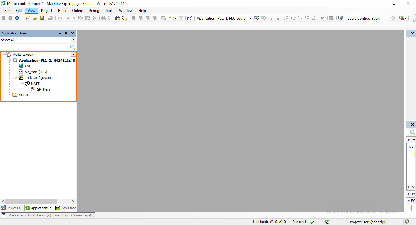
Wait for the project creation process to be done. Once you arrive at the project interface, head to the “Application tree” tab.
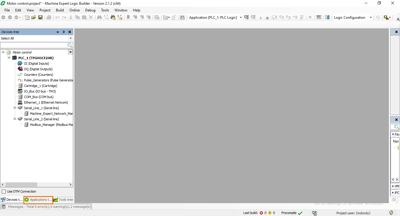
In this section, we will be able to create PLC programs, GLVs, and tasks. For more details, take a look at the Machine Expert introduction tutorial.
Programming a Function Block in ladder
We will start programming our PLC application. Here, we will create a simple motor control application using the Ladder language. As a reminder, the motor control application consists of controlling a motor to either start it or stop it using boolean variables. To make sure that the motor starts using impulsions, we need to add an interlock that will keep the motor activated even if the start variable falls to 0. The program will be located in a Function Block which will be called in the main program (SR_Main).
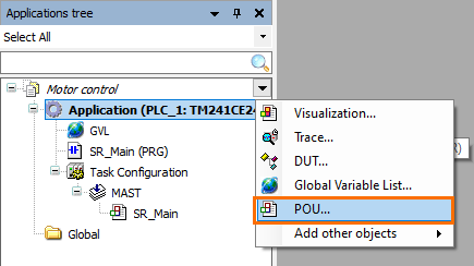
First, let’s create the Function Block. Click on the green plus button next to the “Application” section and select “POU.”
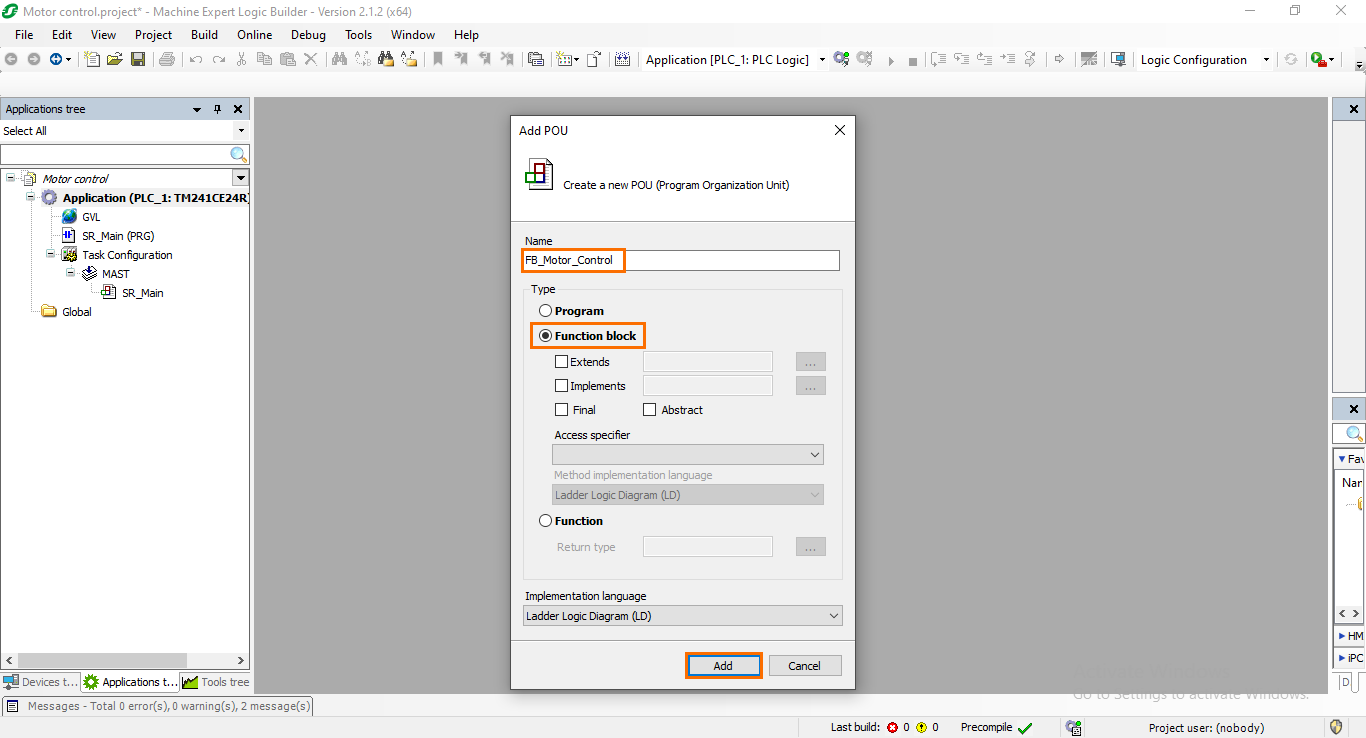
In the POU creation window, give a name to the POU (“FB_Motor_Control” for example) and select “Function Block” as the type. Once done, click on “OK.”
Once the FB is created, it will appear in your application. Open it to display its programming interface. As a reminder, the programming interface is split into two parts: The variables zone where you define local variables, and the programming zone where you assemble instructions in networks.
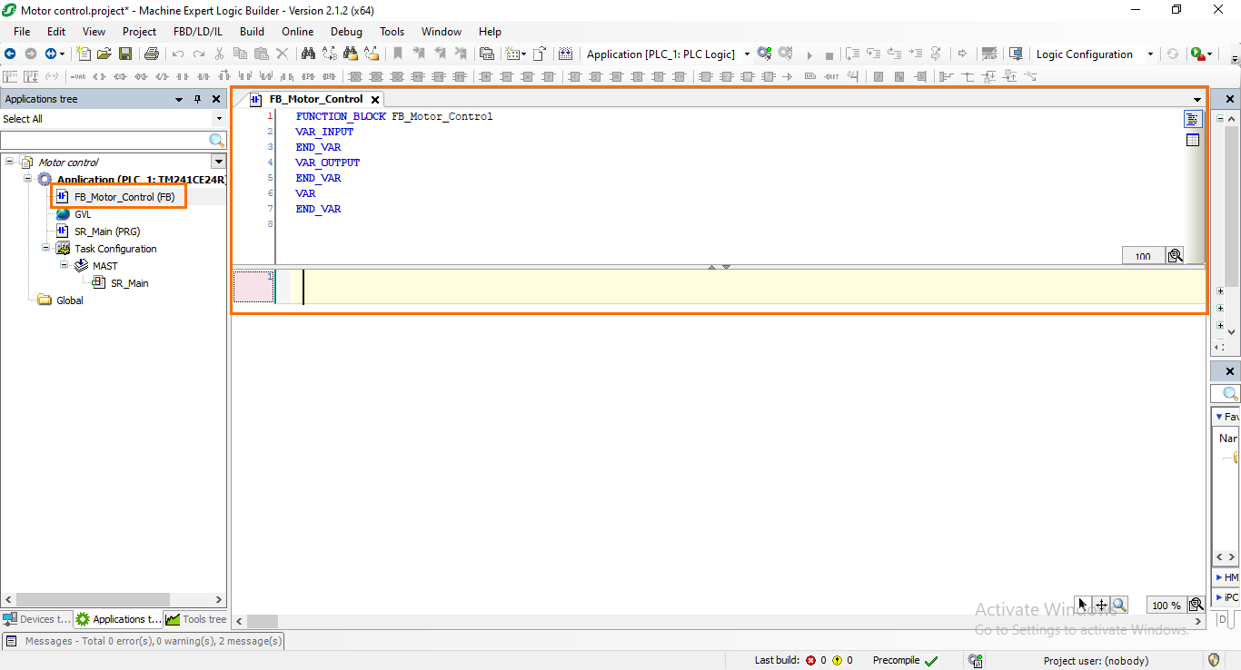
You can find all the usual instructions (such as NO/NC contacts, coils, rising/falling edges, timers, counters…etc) in the instructions toolbar.

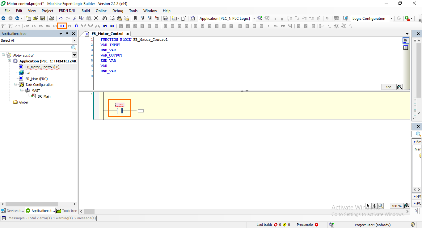
Let’s start assembling the motor control program. First, we need to add an NO contact that will represent our motor start variable. Select Network 1 and click on the NO contact button. You should see it appear in the program as follows.
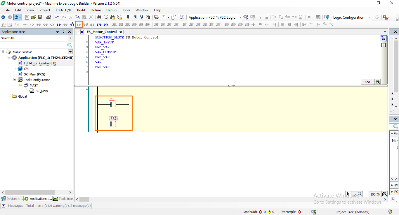
Next, we need to add another NO contact in parallel with the first one to create the interlock. Select the first NO contact and click on the “Add parallel NO” button.
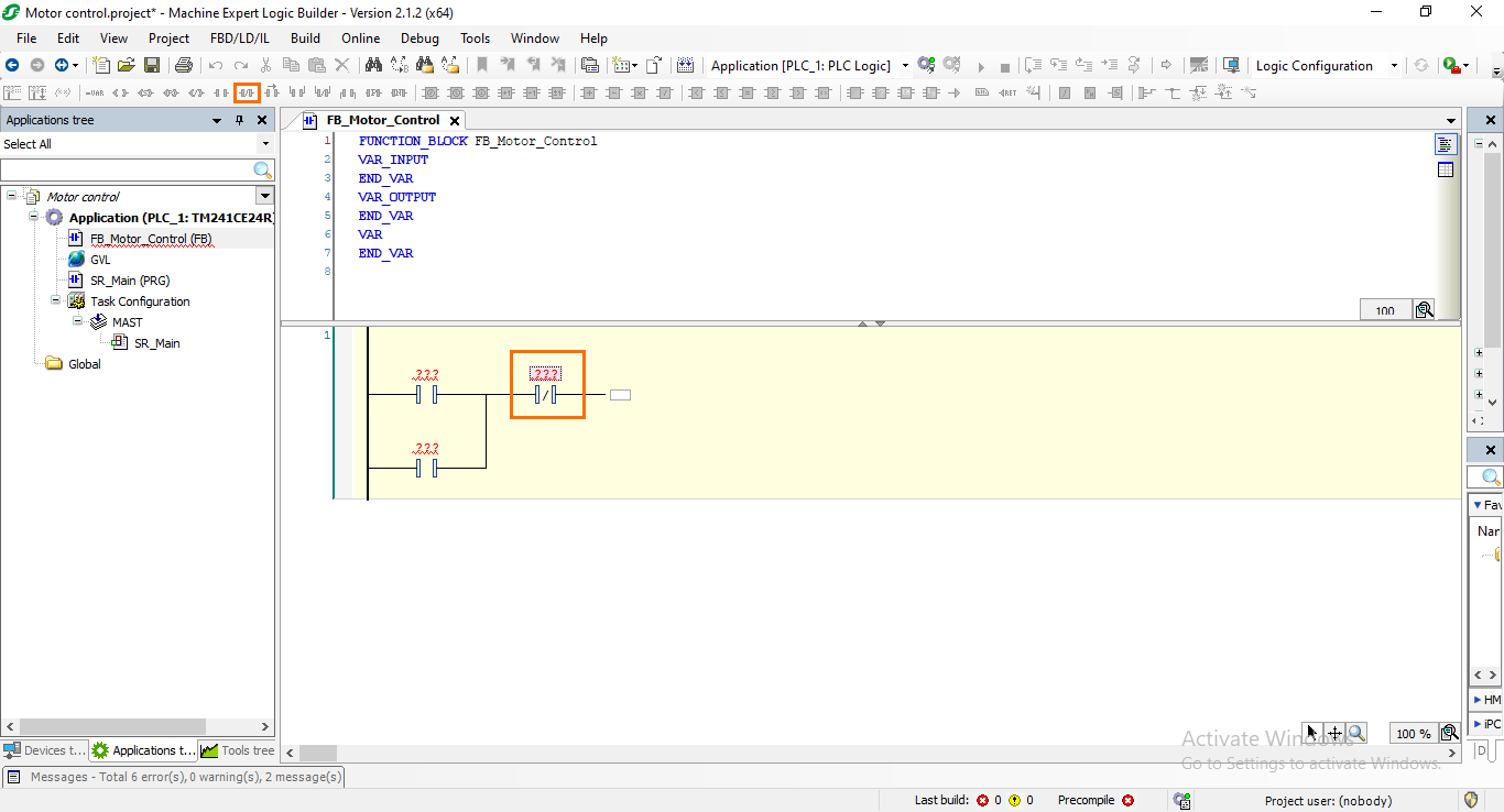
After that, we need to add an NC contact in serial with the two previous NO contacts that will serve as the stop variable. Select the right end of the parallel branches and click on the “Add NC contact” button.
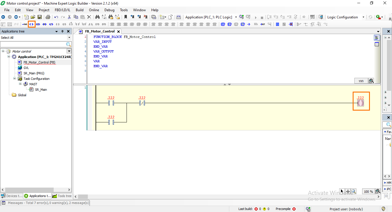
Then, the last instruction we need to add is a coil at the end of the main branch that will control and indicate the motor’s state. Select the right end of the NC contact and click on the “Add coil” button.
Defining the FB’s local variables
As you surely noticed, all the instructions we just added have red “???” above them. This signifies that no variables are associated with them. To make our FB more structured and reusable, we will define local input and output variables that will represent the FB’s interface. All interactions between the FB and any external component will be done through this interface.
For this motor application, we need to define two boolean local inputs; Motor start and Motor stop. And one boolean local output; Motor state. This will be done using the textual view of the variables section. (You can find more details about the variable section’s textual and tabular view in the Machine Expert introduction tutorial).
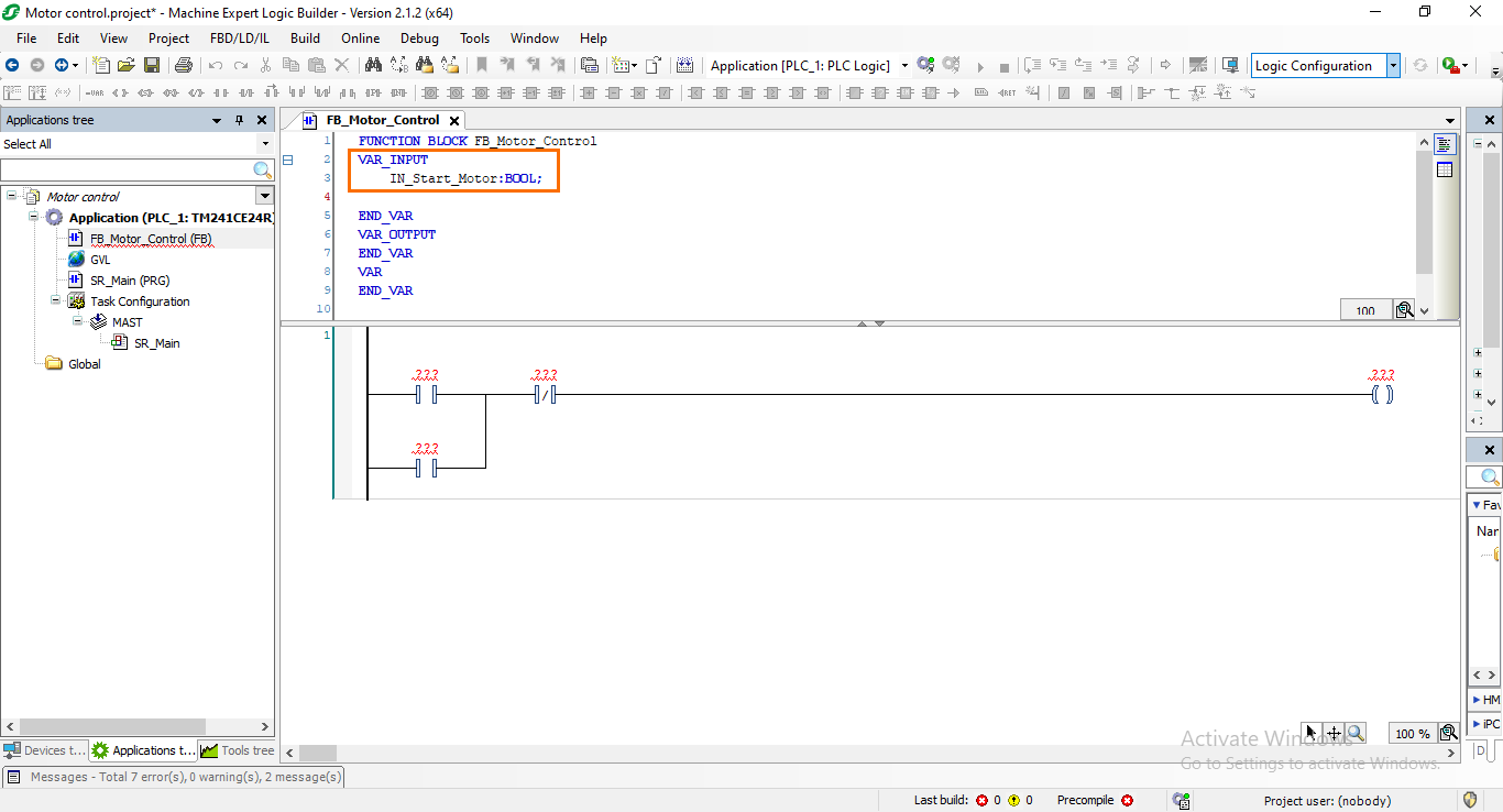
The first variable we’ll define is the motor start variable which we’ll call “IN_Start_Motor” (The “IN” indicates that it’s input. The same will apply to the “OUT” mention for outputs). Under the “VAR_INPUT” section type the following:
IN_Start_Motor:BOOL;
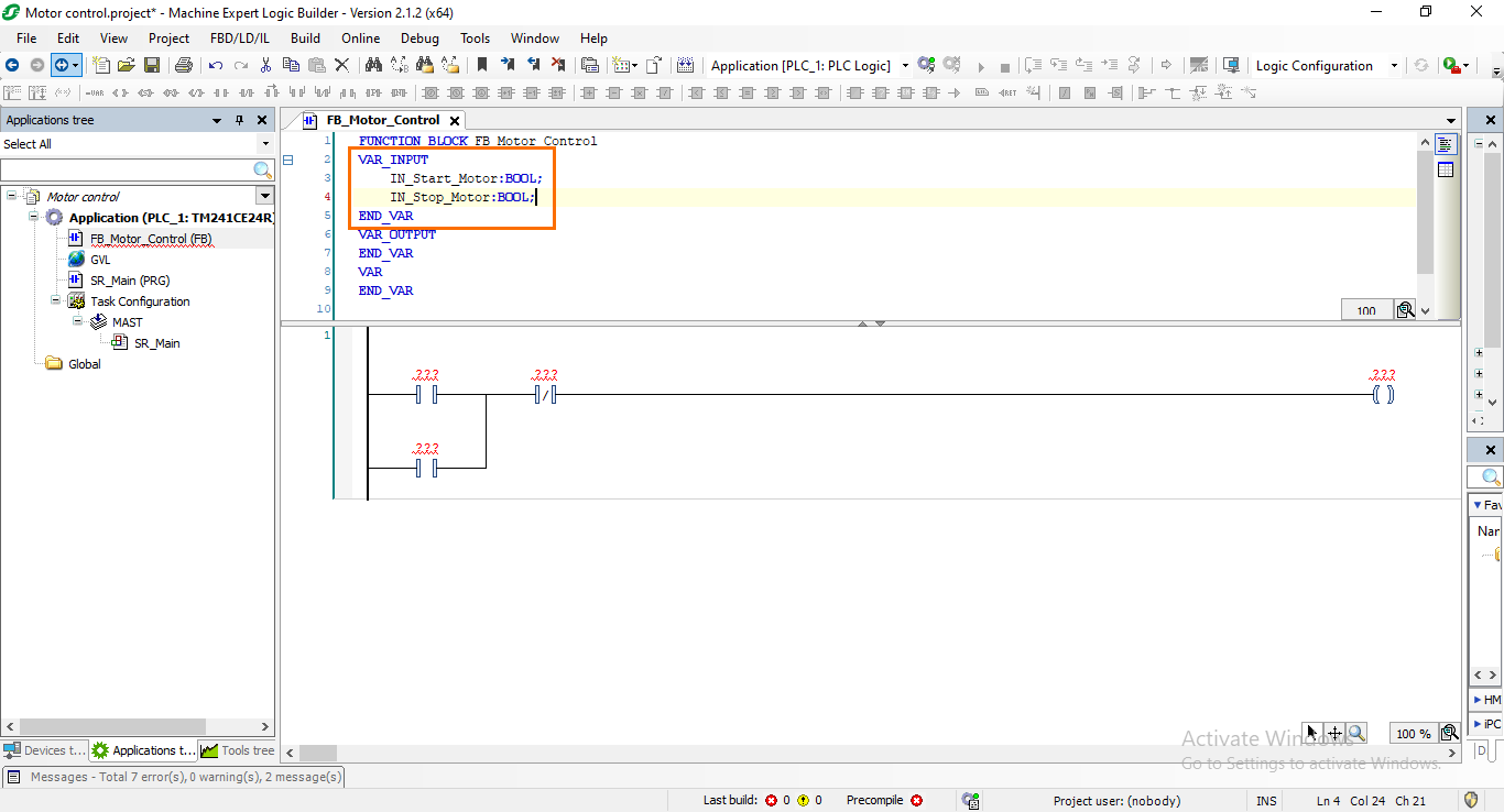
Next, we will apply the same logic to create the motor stop variable. Right under the first variable, add the following text:
IN_Stop_Motor:BOOL;
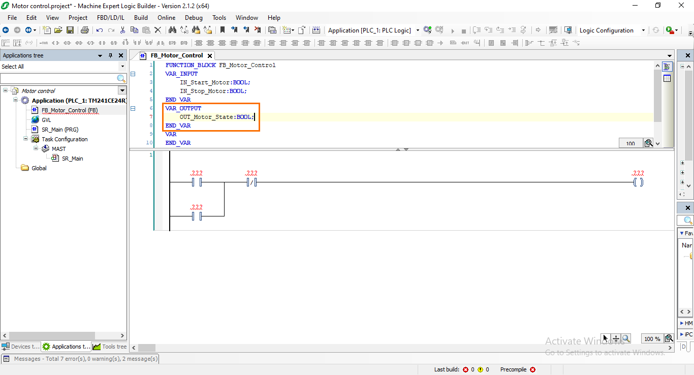
After that, we need to add a local output. This means that the next variable we’ll create will be under the “VAR_OUTPUT” section. Type the following text under the “VAR_OUTPUT” section:
OUT_Motor_State:BOOl;
Adding local variables to the program
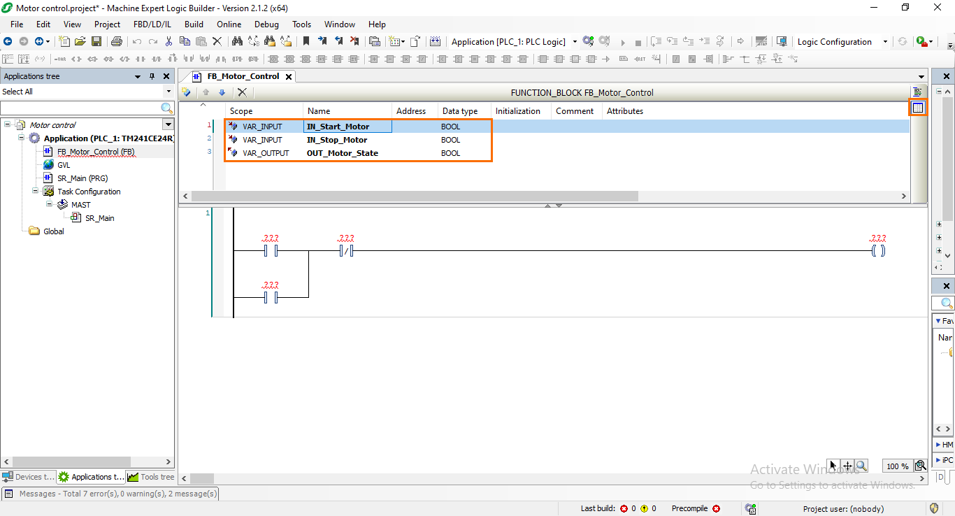
Now that we created all the local variables we need, we can add them to the program we assembled previously. To facilitate this, we will switch to the tabular view of the local variables section. To do this, click on the “Tabular view” button.
There are three ways to add a variable to an instruction:
- You can drag it from the variable zone (In tabular view) and drop it in the desired instruction.
- Directly type the variable’s name in the instruction.
- Selecting the variable from a variable list.
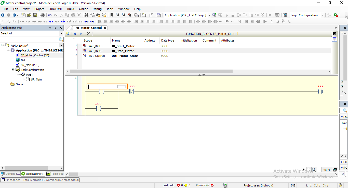
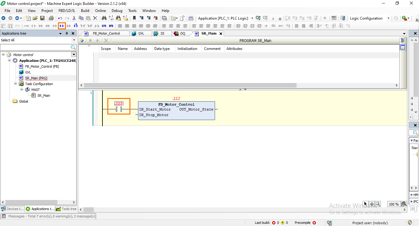
Let’s go through the third option. Click on the red “???” of the first instruction to turn into edition mode. Then, click on the grey square on the left.
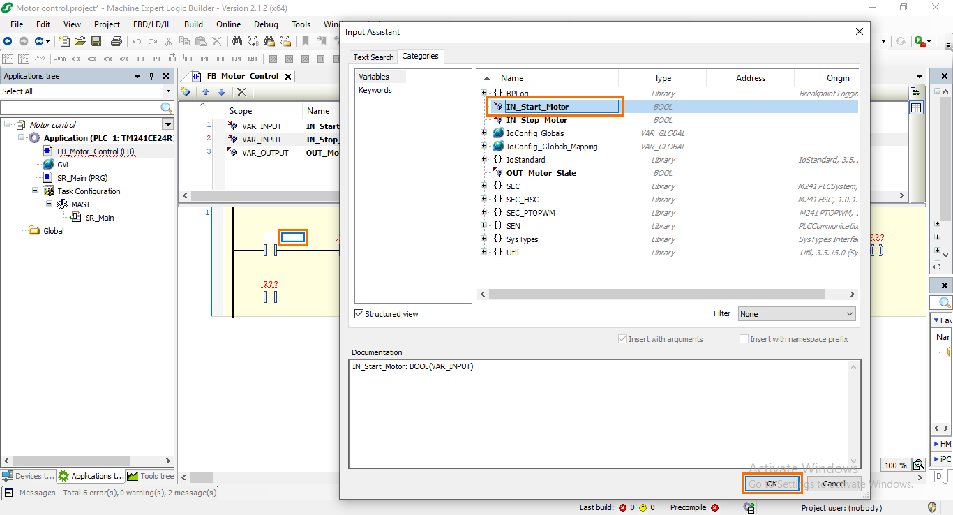
This will display an assistant that contains a list of all the variables in your current program. Since we are working on the first instruction (Motor start), select the “IN_Start_Motor” variable then click on “OK.”
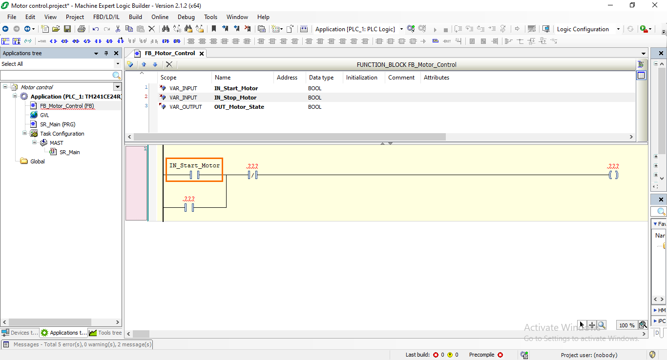
This will automatically associate the variable with the chosen instruction.
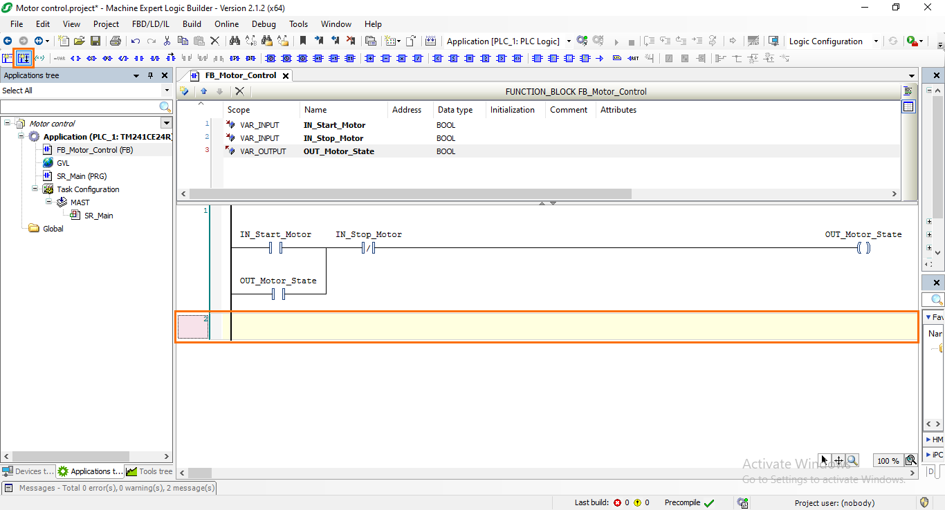
After that, repeat the same process to associate the remaining variables as shown in the following figure.

Programming a timer instruction
To demonstrate how timers and similar types of instructions are programmed, we will add another section to our program inside Network 2. For this example, The new section we will add is a motor security in the form of a timer that will trigger when the motor is turned off and will prevent it from being turned on for a certain amount of time.
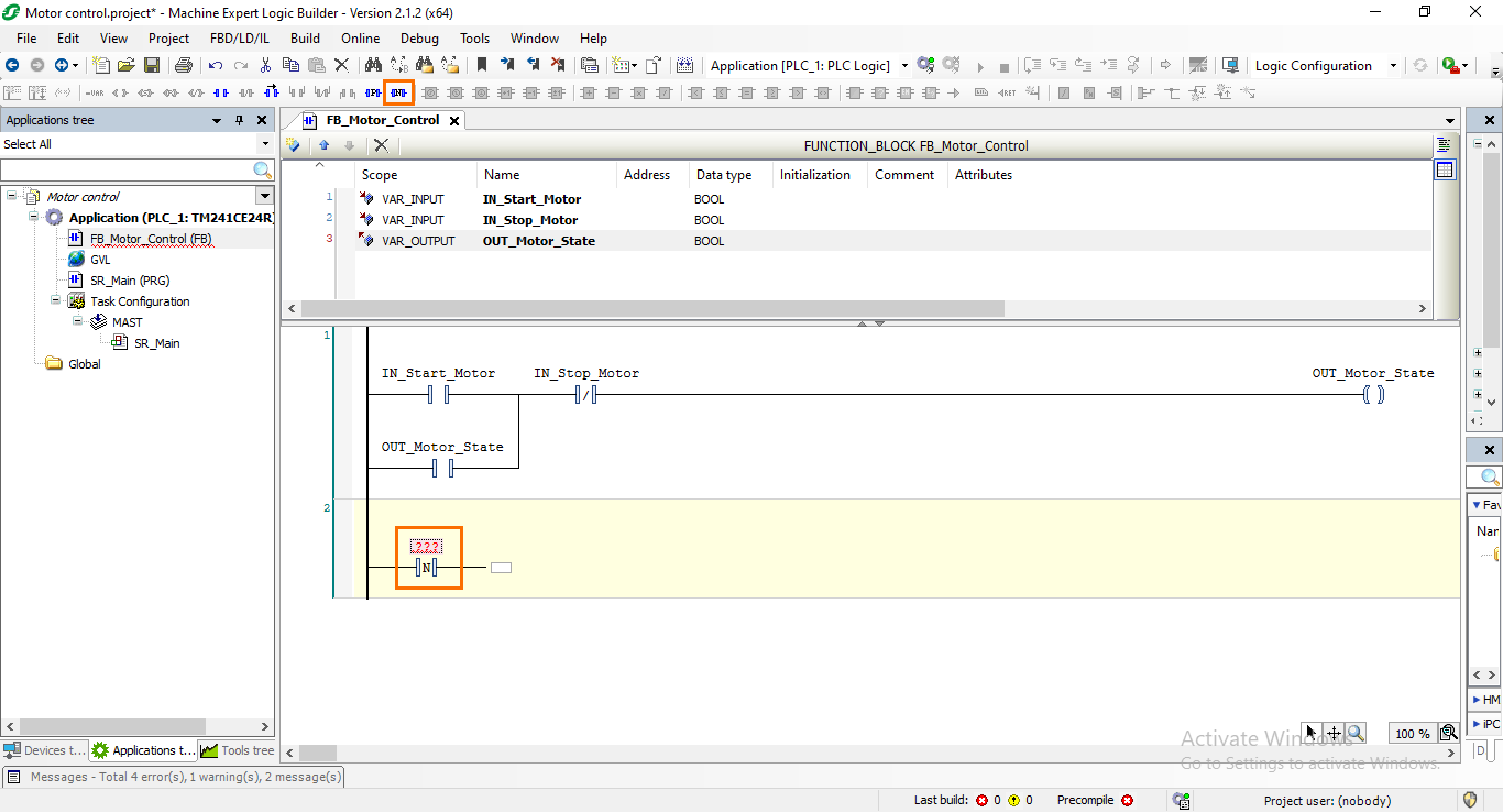
First, create a new network (Network 2) by clicking on the “Add network below” button.
Then, we need to add an instruction that will serve as a trigger for the timer. Since this will be triggered by the motor being turned off, we need to use a falling edge instruction. Select Network 2 and click on the “Add negative edge” button.
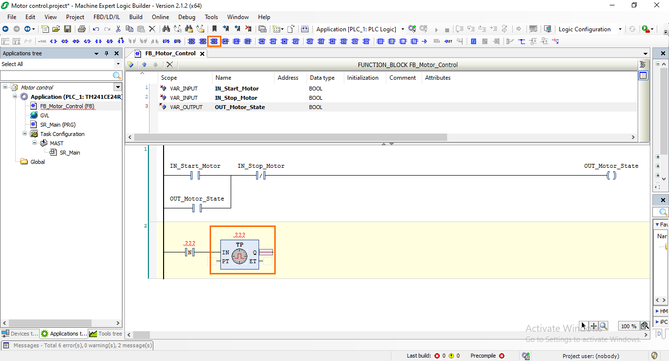
Next, we need to add the timer instruction. There are many types of timers available, the one we need in our application is the TP Pulse timer. You can check the differences between the timer instructions in the Machine Expert’s official documentation.
Select the right end of the falling edge instruction and click on the “Add TP timer” button.
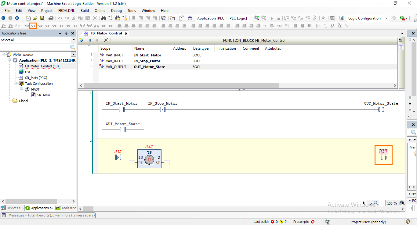
Then, we need to add a coil that will be controlled by the timer output. We will associate a variable with this coil that will serve as a security flag.
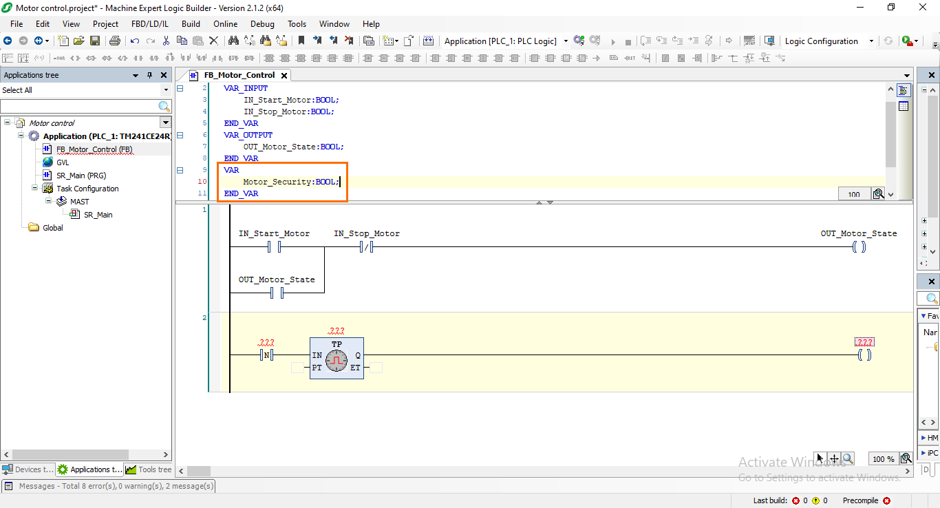
We are done building this part of the program, let’s define the needed variables. First, we’ll define the security variable. Since it doesn’t need to be a local input or output, we can define it as a simple local variable. Type the following text under the “VAR” section of the variables zone:
Motor_Security:BOOL;
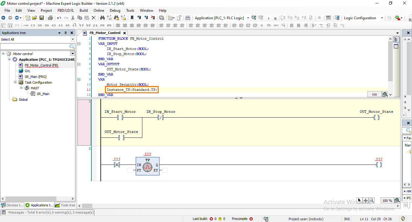
As you may have noticed, the timer instruction also has a red “???” above it. It doesn’t require a variable in that spot but an instance. Instances are used to differentiate between multiple timers in the same program. It is declared similarly to a local variable though. Still, under the “VAR” section, type the following text to define the timer’s instance:
Instance_TP:Standard.TP;
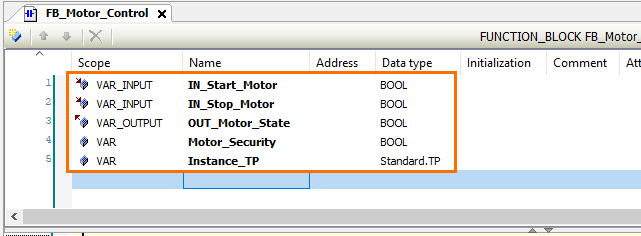
If you switch to the tabular view, you should obtain a similar list as the following.
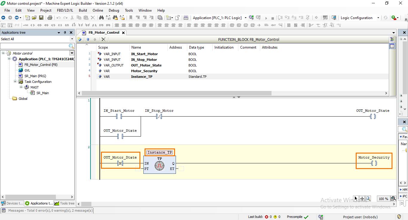
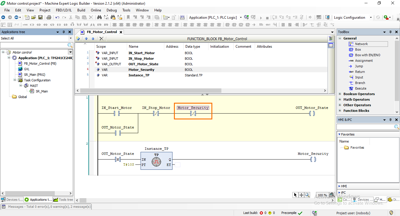
Then, you can proceed to add the correct variables to the newly created program by either dragging and roping them from the tabular view or going through the variables list as we did earlier. You should obtain a program similar to the following.
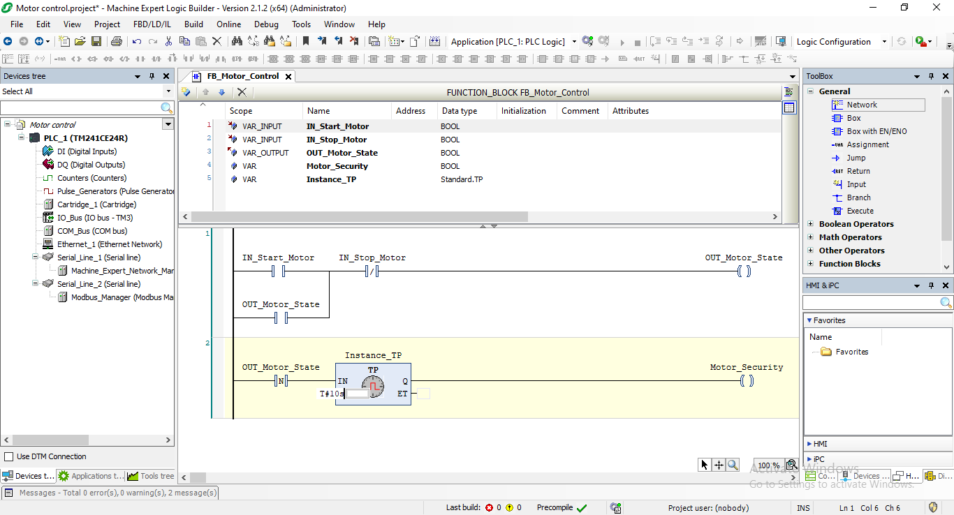
After that, the next thing we need to do is to define a preset time for the timer. For this example, we will define a PT of 10 seconds. Click on the “PT” input of the timer instruction to make it editable then type the following time-formatted text:
T#10s
For the last step, we need to integrate the motor security variable back into the motor control program. Go back to Network 1 and select the space to the right of the “IN_Stop_Motor” NC contact. Then, add a new NC contact and link it to the “Motor_Security” variable.
Defining global variables (GVL) and DI/DQ mapping
We are done programming the motor control FB. We need now to define the global variables that we will use in the FB’s interface. For this, we will use a GVL (Global Variable List) and define the three variables we need; Motor start, stop, and state. After that, these variables will be mapped to digital inputs and outputs that will serve to connect them to physical buttons.
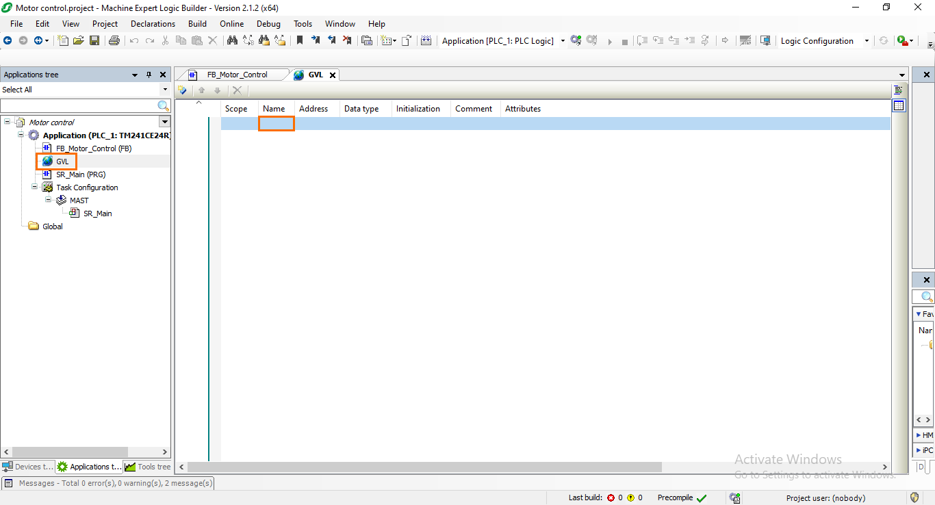
A GVL is already created in your program when creating the project by default. Open this GVL then click on the empty space in the name section of the first row to start defining a variable.
To create a variable, type its name then press Enter. Here, we will create a variable named “Start_button.”
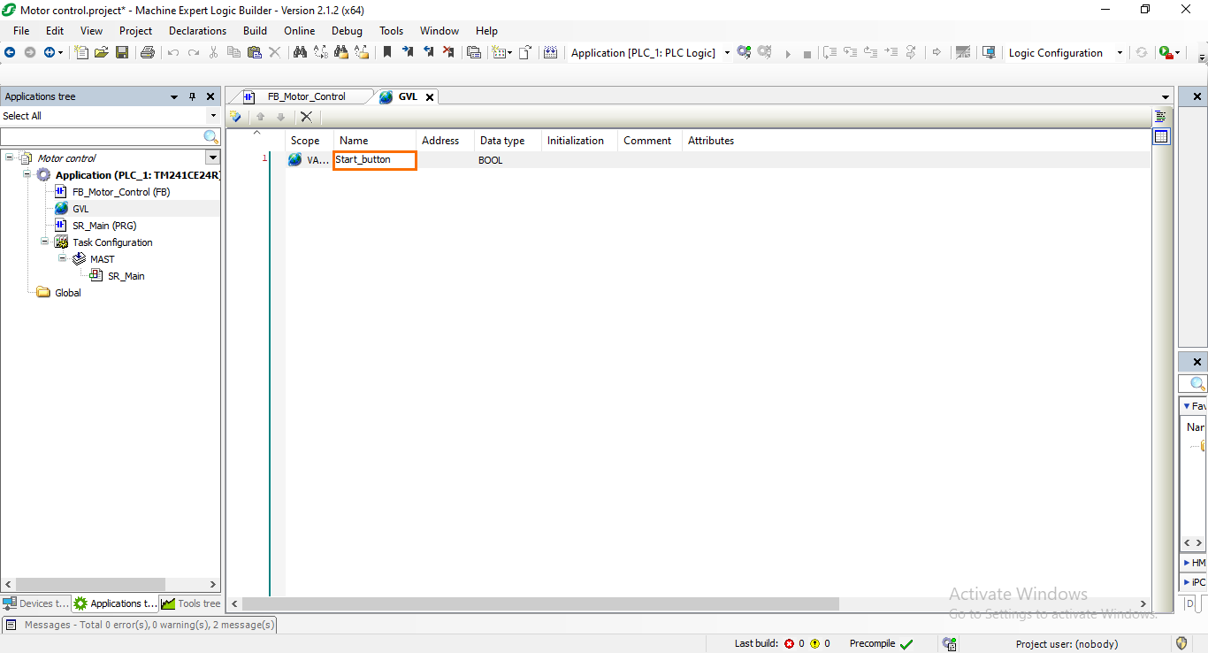
NB: Variables are created as booleans by default. Since it is the data type we need, we will keep them as is.
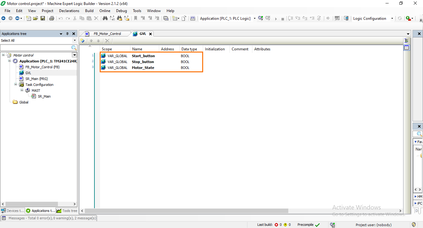
Repeat the same operation to create the “Stop_button” and “Motor_state” variables.
Head now to the DI/DQ sections of the Device tree. Here, we will bind the variables we just created in the GVL to physical digital inputs and outputs. This operation is called mapping and it is used to make the DI/DQ easily accessible and reusable independently of the hardware configuration as GVL variables.
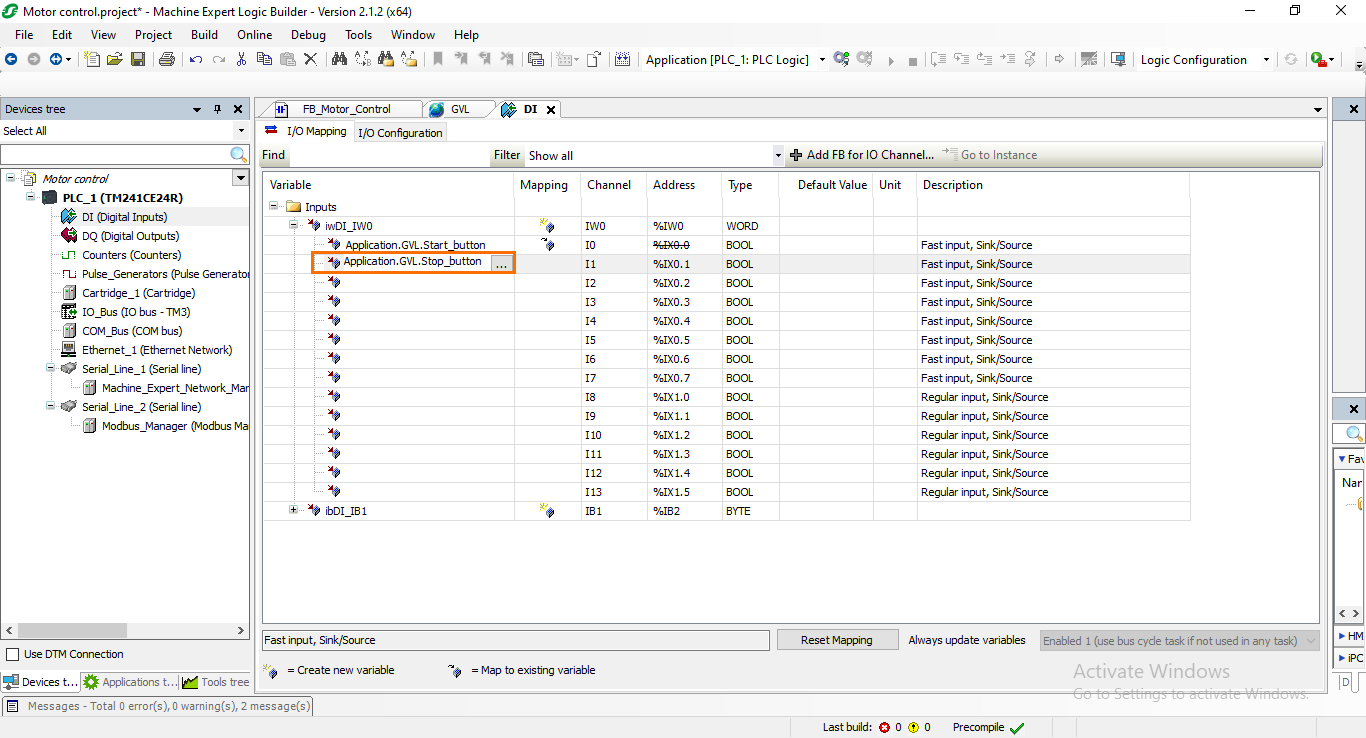
Open the DI section of the Device tree.
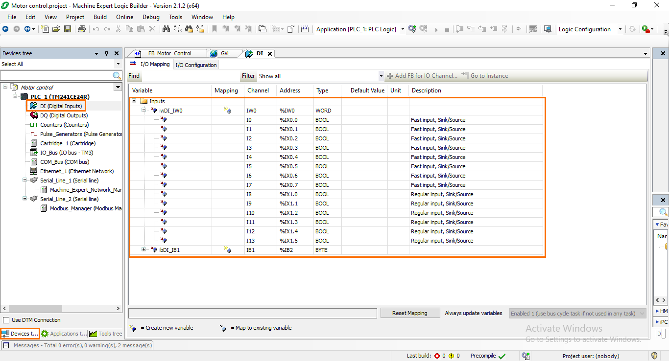
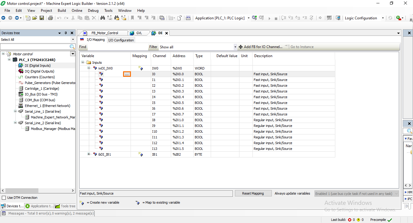
To map a GVL variable to a DI, click on the name section of the selected DI (Here it is I0) then click on the grey three-dotted box that appears.
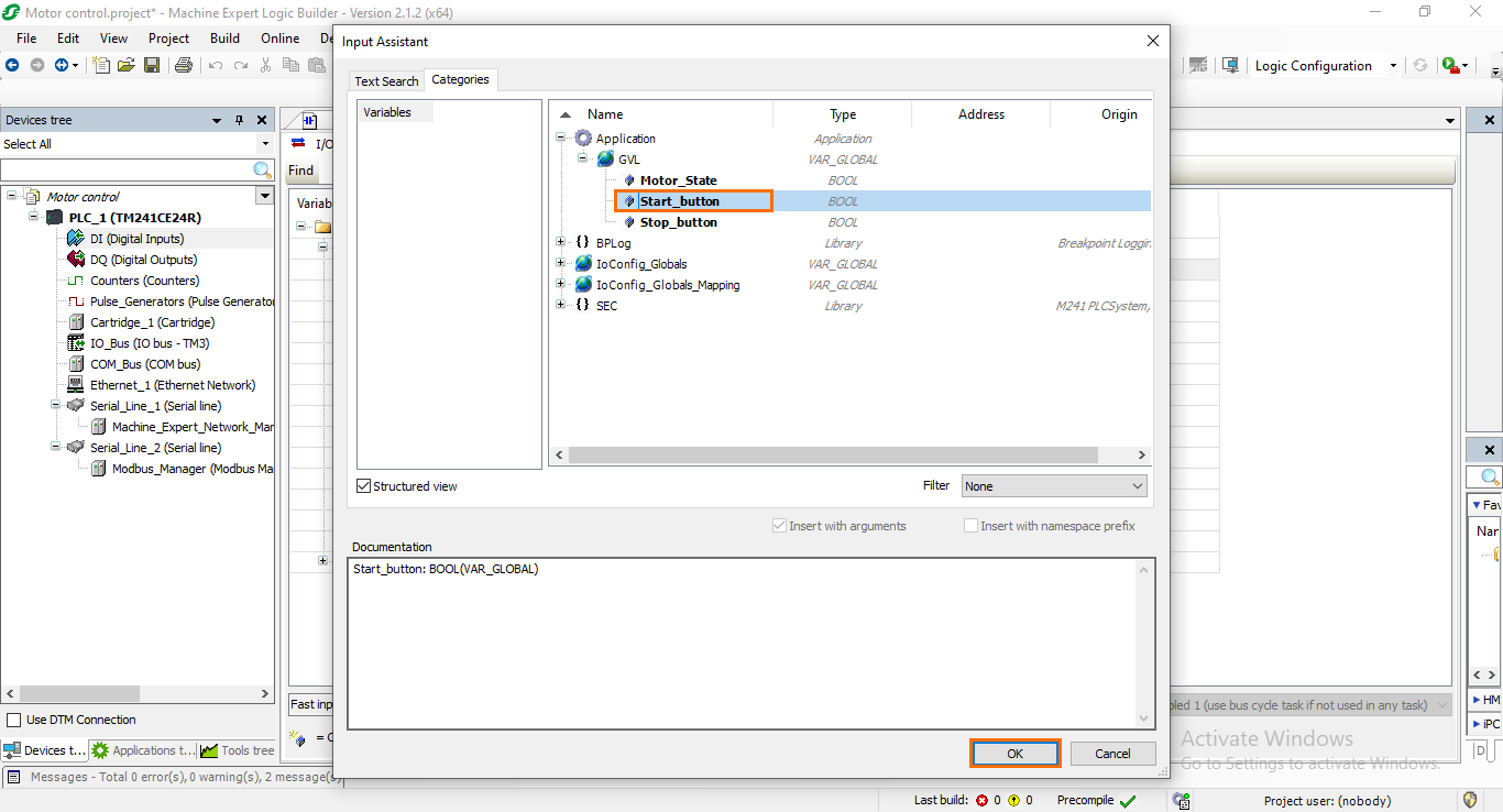
This will open a similar to the one we saw earlier where you can find all the available variables in your program. The variables we are looking for now are located under the “GVL” section. Select the “Start_button” variable then click on “OK.”
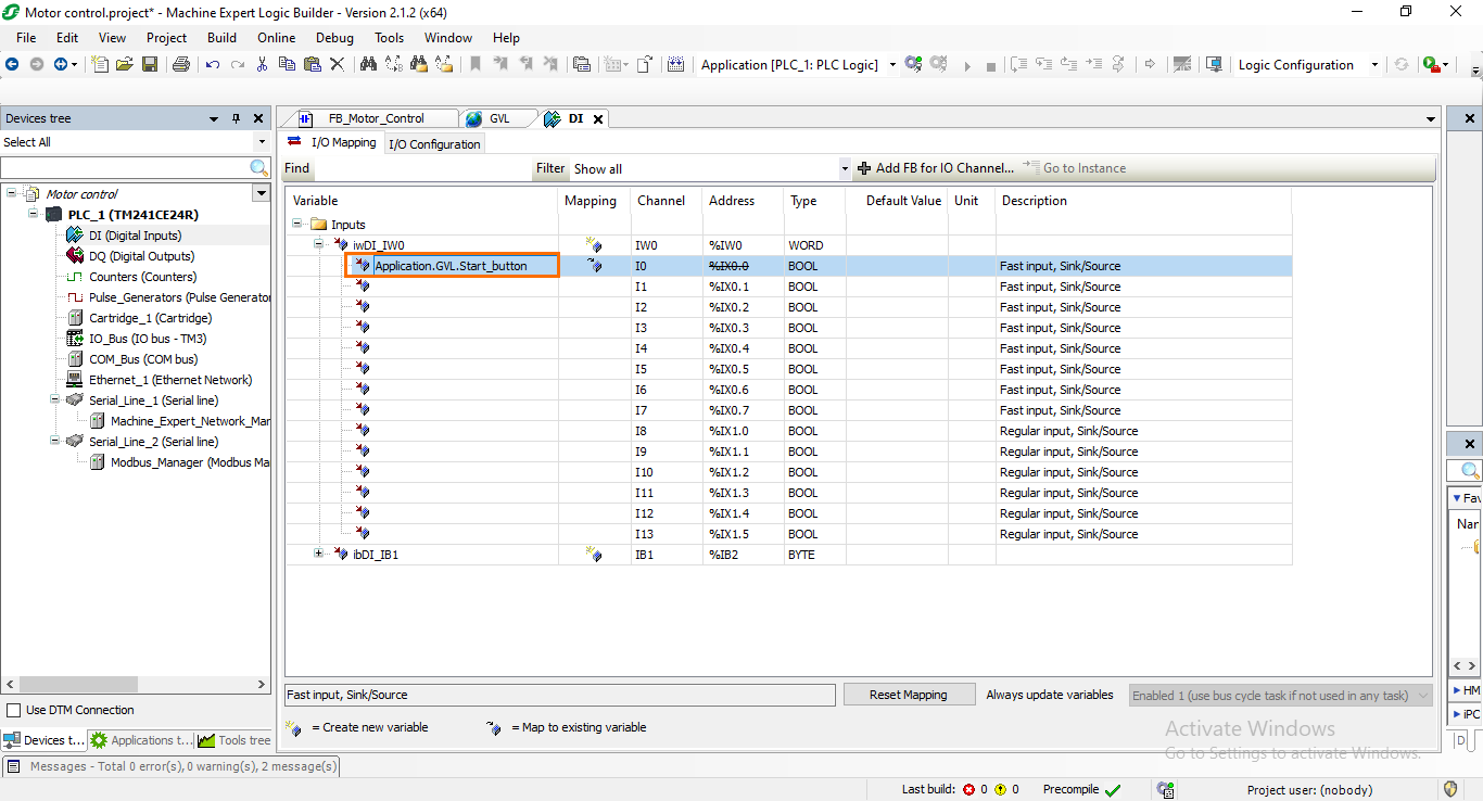
The DI name will automatically become that of the GVL variable we mapped.
Repeat the same process to map the “Stop_button” GVL variable to the I1 DI.
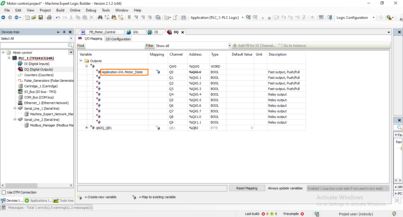
We are with the DIs, let’s head to the DQs. Open the DQ section in the Device tree.
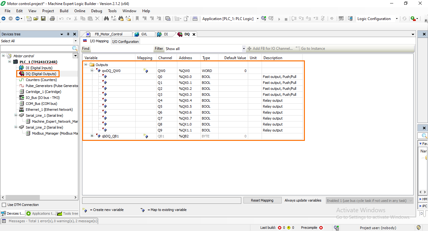
If you attempt to repeat the same operation to map a DQ variable, you will encounter the following error message.
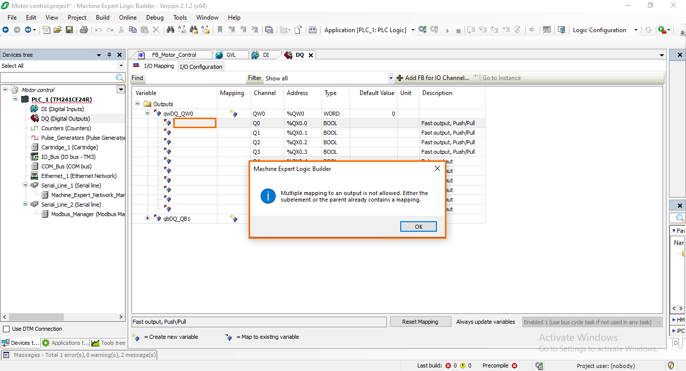
This is caused by the fact that DQs work a little differently from the DIs and do not allow multiple mapping. By default, the entire DQ byte is mapped with a default value (“qwDQ_QW0” in the QW0 row). We need to remove this byte mapping before creating new individual mappings. Select the “qwDQ_QW0” text in the QW0 row and delete it.
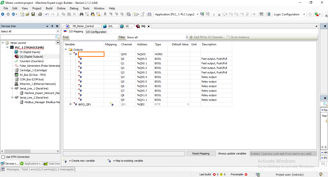
You can now perform DQ mappings the same way we did with the DIs. Map the Q0 output to the “Motor_State” variable of the GVL.
Calling the FB in the main program
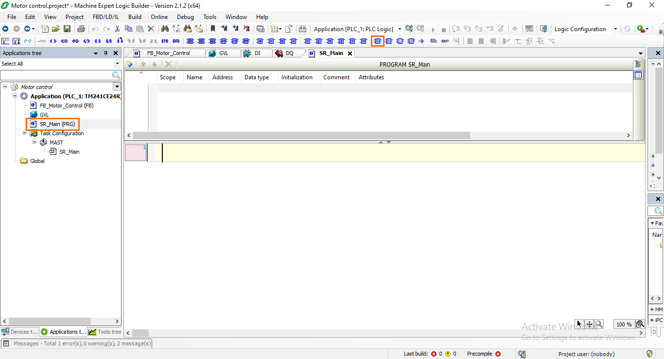
We now come to the last part of the tutorial where we will call the FB we created in the main program (SR_Main). The latter program is executed in the MAST task which is the default main task. Without this call, the FB is not executed by the PLC. It needs to be called in a program that is executed in a task.
Open the “SR_Main” program in the Application tree. You will arrive at a similar programming interface as the FB’s. We need now to call the FB in the program. To do this, select Network 1 and click on the “Add function” button.
This will open an assistant where you can find all the third and first-party functions available in your software. You will find the “FB_Motor_Control” FB under the Application section. Select it and click on “OK.”
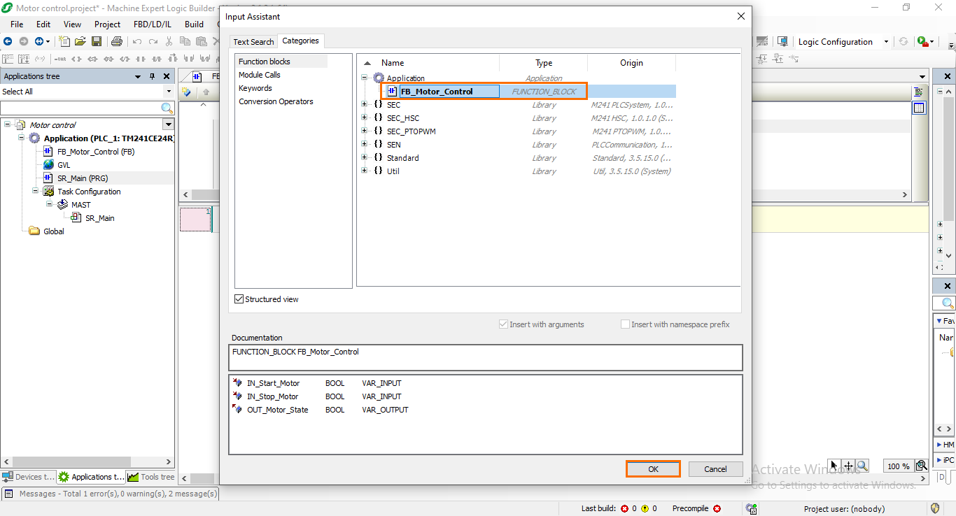
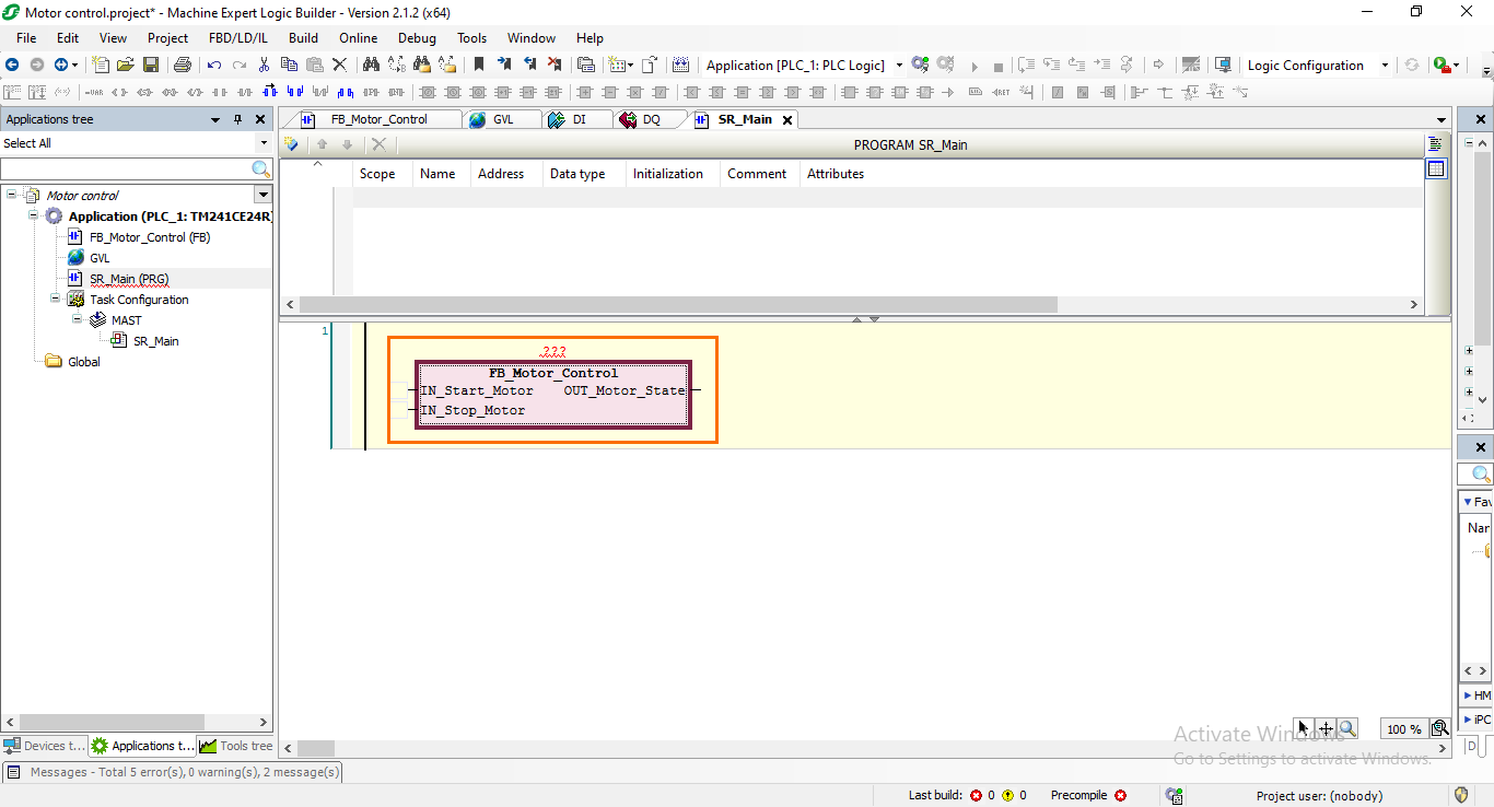
You should see the FB appear as a block in Network 1. It also has all the local inputs and outputs we defined as branches where we can connect other instructions.
We need to add instructions to the FB’s inputs/outputs so we can link them to the GVL variables. First, select the “IN_Start_button” input and click on the “Add NC contact” button.
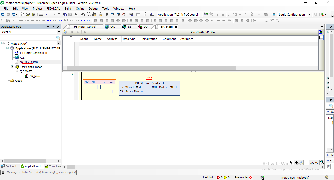
Then, associate this contact with the “Start_button” GVL variable by either selecting it using the assistant or by typing the variable name directly (GVL.Start_Button).
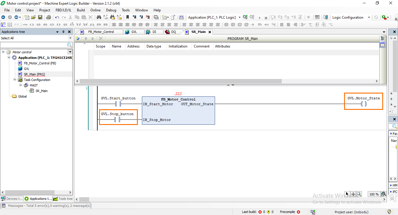
After that, repeat this same operation to associate the remaining input and output with their respective GVL variables as shown in the following figure.
NB: Be sure to add a coil to the output. Not a contact.
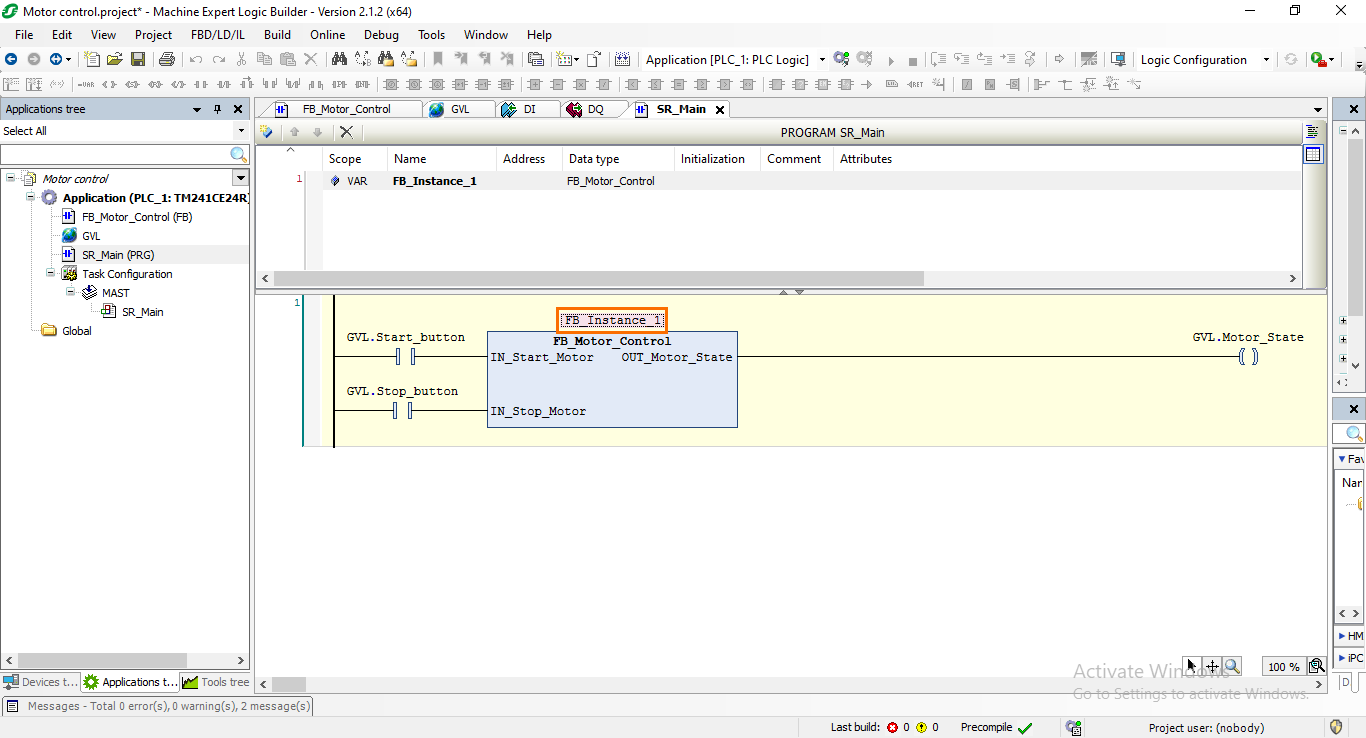
The last thing we need to do is to define an instance for the FB like we did for the timer previously. To do this, type the following text under the “VAR” section in the variable zone in textual view.
FB_Instance_1:Fb_Motor_Control;
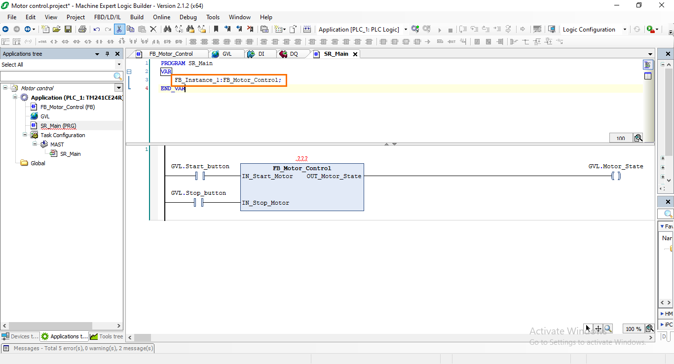
Then, add the defined instance to the FB by either typing the instance name or selecting it using the assistant.
Conclusion
In this tutorial, you learned how to navigate Machine Expert to program Schneider PLCs using the ladder language. We began by creating a new project, selecting the TM241CE24R model, and configuring the project for ladder programming. The focal point of the tutorial was the step-by-step development of a motor control application within a Function Block. This involved defining local variables, and assembling ladder logic with NO/NC contacts, coils, and timers, ensuring a comprehensive understanding of PLC programming fundamentals within Machine Expert. The integration of Global Variable Lists (GVL) was explored to establish a seamless connection between physical inputs and outputs. Finally, you learned how to call the Function Block in the main program and how to interface it with mapped DIs/DQs.
As evident from this tutorial, PLC programming in Machine Expert offers a user-friendly and efficient experience. The platform's intuitive interface and comprehensive features streamline the development process, enabling engineers to create sophisticated control systems with ease. Looking ahead, the next tutorials will delve into Human-Machine Interface (HMI) programming and the integration of PLC/HMI simulation using Machine Expert.
