Simulating TCP/IP Communications using PLCSim Advanced

Introduction
Communications are a large part of the vast majority of industrial systems. While designing these systems, you’ll find the need to test them to check their good working without relying on actual hardware. Yet, making a simulated PLC communicate with an external device is impossible using TIA Portal’s PLCSim. The solution Siemens offers is PLCSim Advanced, a powerful PLC simulator that integrates a virtual network adapter for external communications.
This tutorial will teach you how to simulate a TCP/IP communication between a PLC and an external partner. For this, we will first show how to make two simulated PLCs communicate with each other using open user communication. Then, in the second part, we will replace one of the two PLCs with a simple TCP server coded with Python to demonstrate the capability of PLCSim Advanced to communicate with any type of device in the network.
Prerequisites
To follow this tutorial, you will need the following:
- An installation of TIA Portal and PLCSim Advanced. We will use TIA Portal v17 and PLCSim Advanced v4, but you can use any other versions. No additional hardware or software is required.
- A basic understanding of PLCSim Advanced.
- For the second section of this tutorial, you will also need knowledge about the Python language.
Simulating communication between two PLCs
Let’s start by creating a new project with two PLCs. We’re using here two 1511 CPUs but feel free to use any CPU model. Both PLCs will have similar configurations and programs.

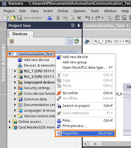
Since we’re using PLCSim Advanced, we need to activate simulation in this project. Right-click on the project folder in the project tree and click on “Properties”.
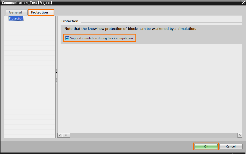
Go to the “Protection” tab and check the “Support simulation during block compilation” checkbox.
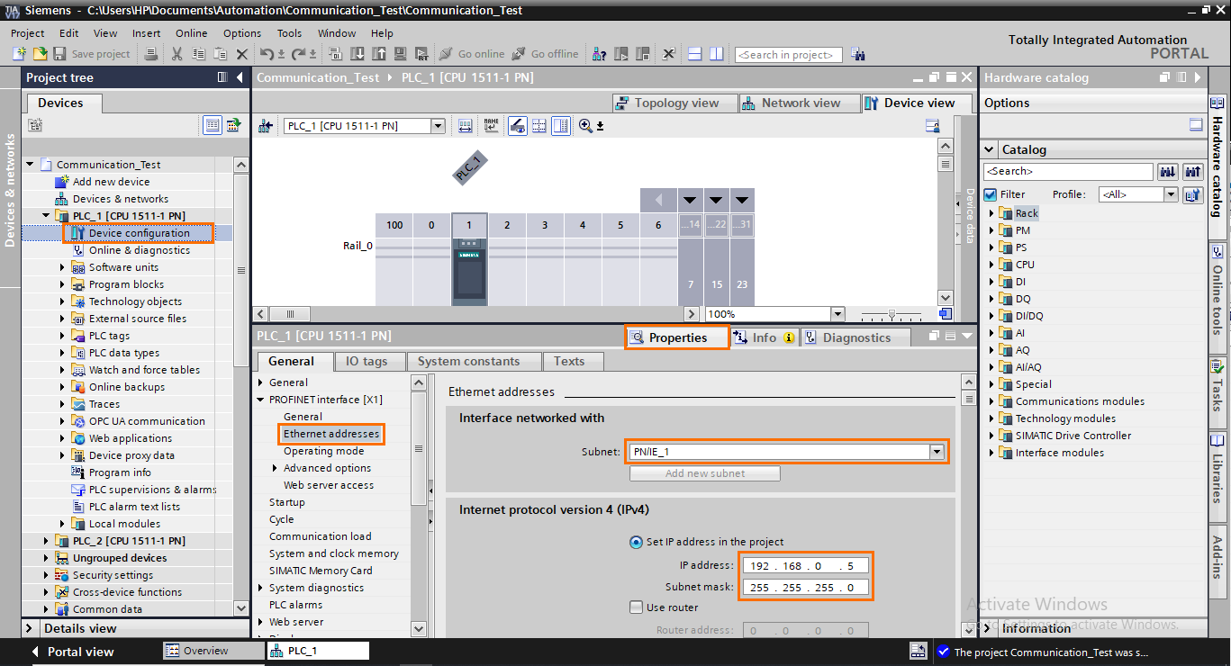
Now we need to configure the PLC’s ethernet interfaces. Open the “Device configuration” of PLC_1, go to the properties and open the “Ethernet addresses” section. Create a new subnet and set the IP address to {192.168.0.5/255.255.255.0}.
Reproduce the last step but for PLC_2. Add it to the same subnet (PN/IE_1) and set the IP address 192.168.0.6 with the same subnet mask.
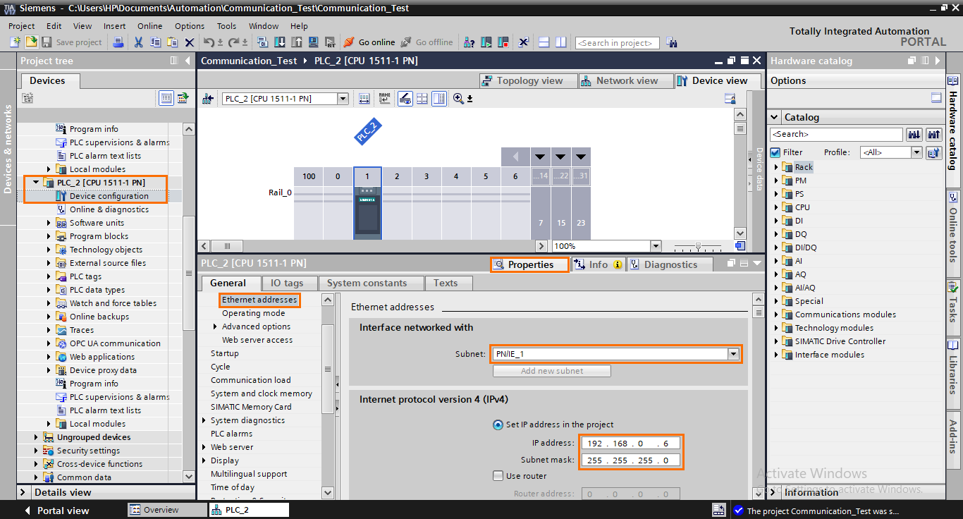
NB: You can use any IP addresses your want. Just make sure to assign different addresses to each device.
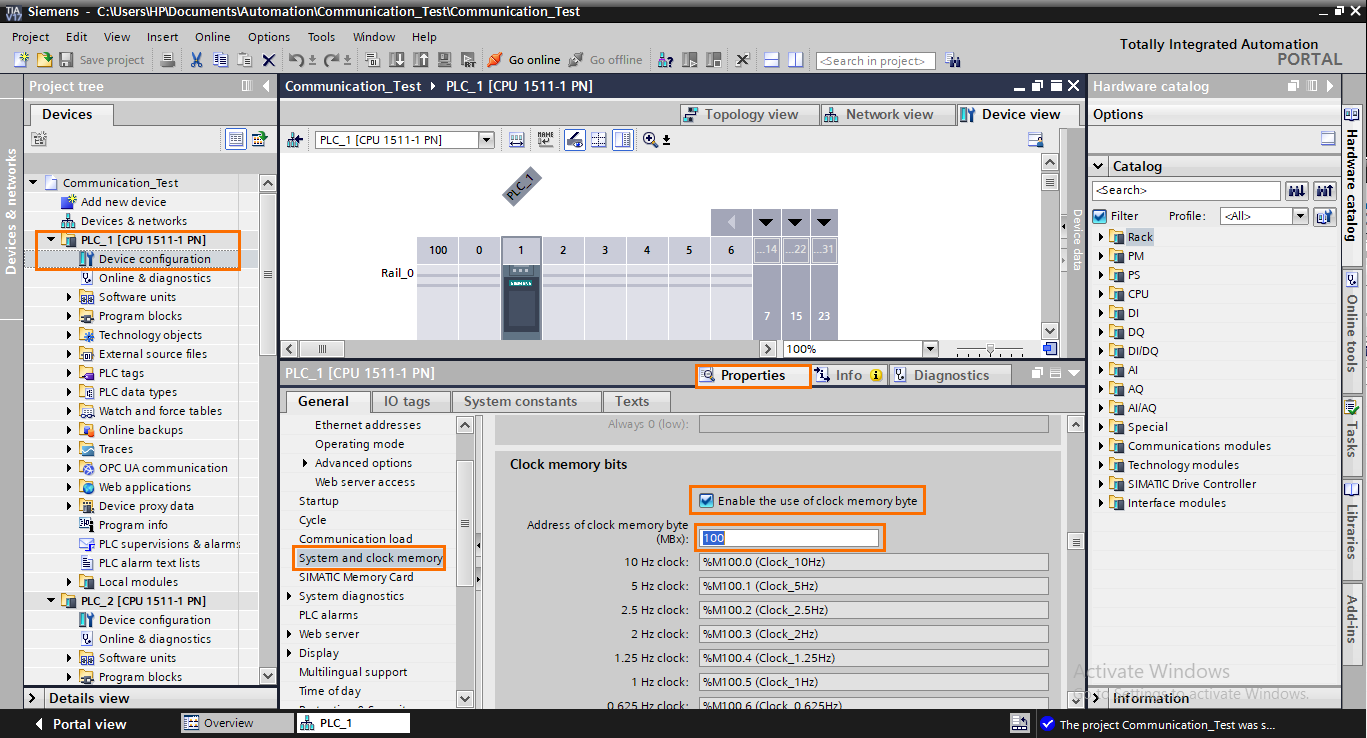
Next, go back to the properties of PLC_1 then the “System and clock memory” section. Check the “Enable the use of clock memory byte” check box. This option allows you to associate each bit of a memory byte with signal clocks with different frequencies. We will need it later in the tutorial. You can select which memory byte to use in the “Address of clock memory byte” section. I prefer having the clock byte far away from the low addresses. So I’m using the MW100 byte. Repeat this step for PLC_2 as well.
For the programs, in addition to the main program, we will also need a DB that will contain the sent and received messages.

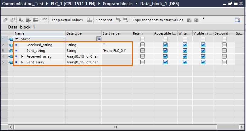
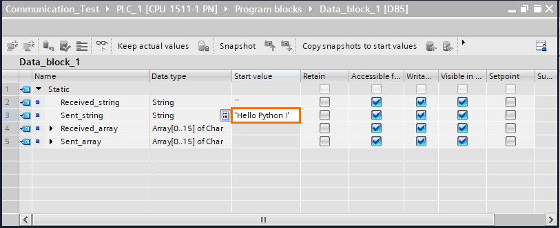
This DB will contain the exchanged messages. We need four variables: Two variables defined as strings (send and receive as strings) and two variables as arrays of 16 characters (send and receive as Array[0..15] of Char). The string variables are used for convenience and clarity. The program contains a part that converts these strings to the desired arrays when it comes to send/receive the data.
The TCP communication sends data byte by byte. When you want to send or receive strings, we need to use arrays of characters in the Siemens environment since Siemens’ string format differs from classic formats (it has an additional header of 2 bytes). To match the correct data format during the communication and prevent lags, we must use arrays of characters.
Create the four variables as shown below. Be sure to write the message you want to send in the start value of the send string.
Now, to the main program. Both PLCs will have the same programs. Select the main program (OB1) of PLC_1, open it, and create the following networks:
- Network 1:
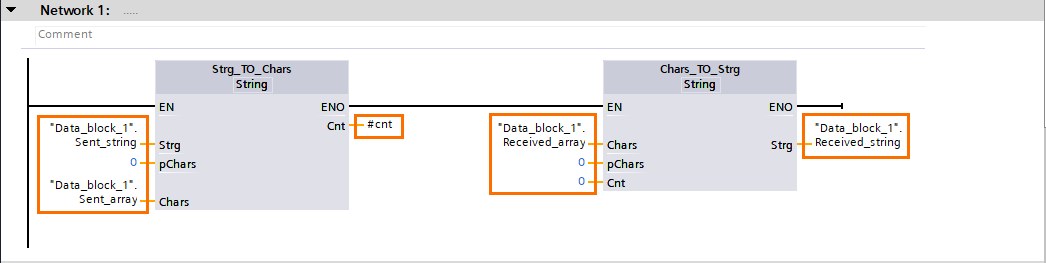
Network 1 contains two instructions that convert the variables contained in the DB. The first instruction, “Strg_TO_Char”, converts the content Send_string to an array of characters and puts it in Send_Array. This way, we just need to modify the content of Send_string to change the message we want to send.
The second instruction, “Char_TO_Strg”, converts the content of Received_array and converts it to a string. We can easily read the received message in string format directly in Received_string.
NB: Except for Strg and Chars inputs, edit all parameters to 0 except for the Cnt output of “Strg_TO_Char” which is mandatory. You can simply define a local variable for it.
- Network 2:

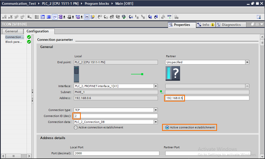
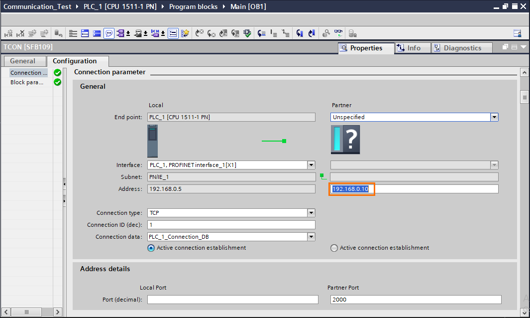
Network 2 contains a TCON instruction that will allow us to send a connection request when the “Connect” bit is set to 1. The ID and CONNECT inputs are configured in the block’s properties section as follows:
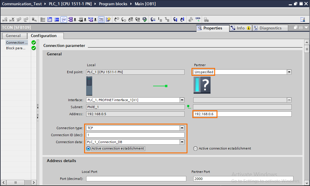
Set the Partner to “Unspecified” so this can work with any type of partner. Then create a new connection DB in the Connection data section. Once done, add the target partner's IP address (the IP address of PLC_2). PLC_1 will act as a client so the “Active connection establishment” is activated on the local side.
For PLC_2, this configuration will be the same except for the “Active connection establishment,” which is set to the Partner side. The connection ID must be different, so it’s set to 2, and the IP address of PLC_1 must be specified.
NB: For more details about the communication instructions, check out the Open User Communication in Siemens TIA Portal tutorial.
- Network 3:
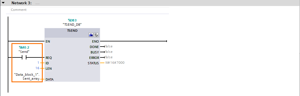
Network 3 contains a TSEND instruction to send data through an established connection. When the “Send” bit is set to 1, the content DATA is sent to the partner. the LEN input is set to 16 because we are sending 16 characters, and the ID input must contain the same ID as the set in the TCON instruction.
- Network 4:
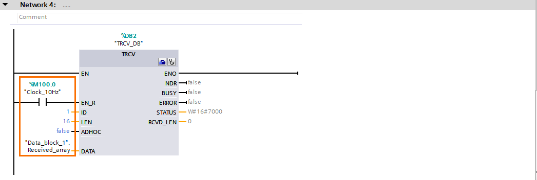
Network 4 contains a TRCV instruction that will attempt to receive data periodically. The enable input is connected to a 10Hz clock bit (M100.0) which means the instruction is activated 10 times per second. This allows us to catch incoming data while limiting resource consumption. You can try lower clock frequencies according to your application. The ID and LEN inputs are set like the TSEND instruction.
The Program of PLC 2 will be different in the configuration of TCON and the IDs in the TSEND and TRCV instructions.

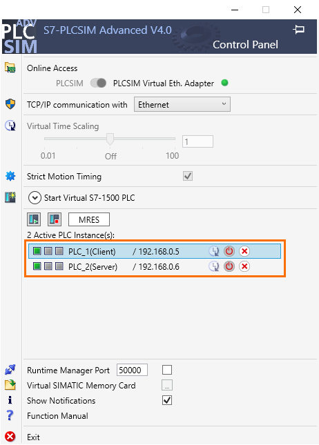
The program is done. We can create the two PLC instances and simulate them. Start PLCSim Advanced, set the Online Access to “PLCSIM Virtual Eth. Adapter” and the TCP/IP communication to “Ethernet”. Then, set the instance name, IP address subnet mask, and PLC family of PLC_1 and start.
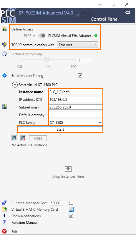
After that, do the same for PLC_2.
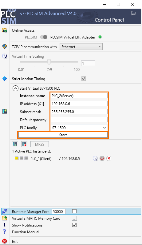
The two instances are active and ready to be used.

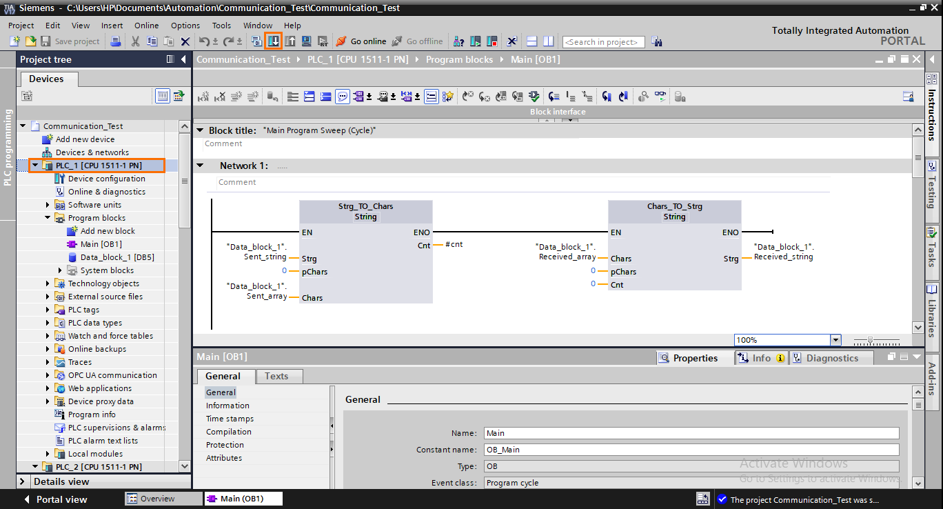
Go back to TIA, select PLC_1 in the project tree, and click on the “Download to device” button.
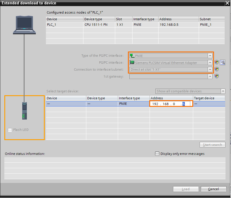
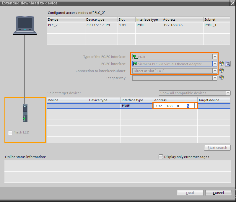
Select “PN/IE” as PG/PC interface type and “Siemens PLCSIM Virtual Ethernet Adapter” as PG/PC interface. Then, type the IP address of PLC_1 in the target section to load the program to this specific PLC and press enter.
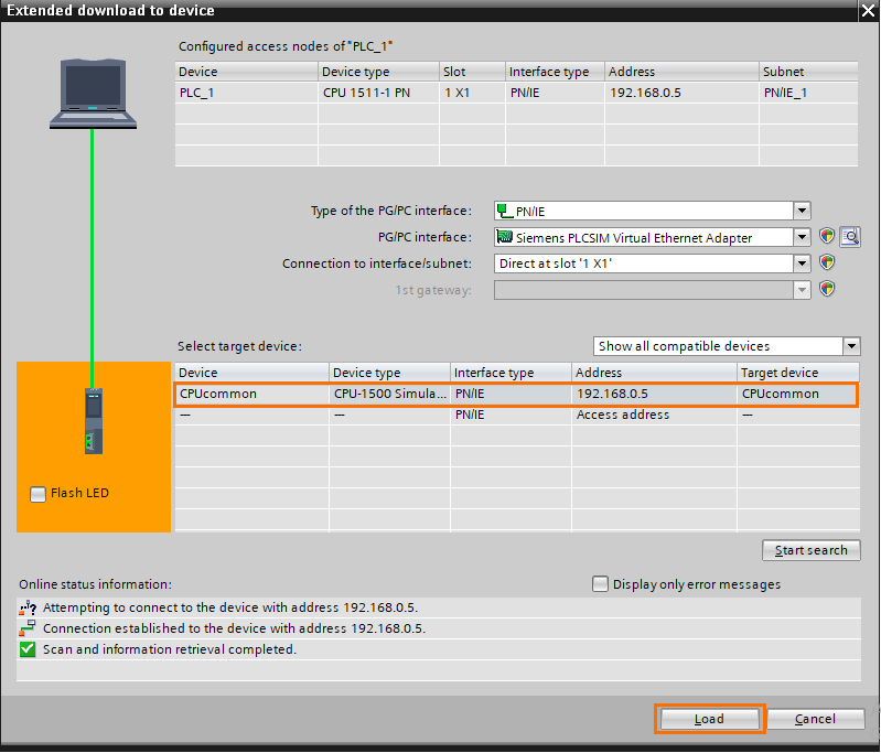
Once the simulated CPU is detected, click on “Load”.
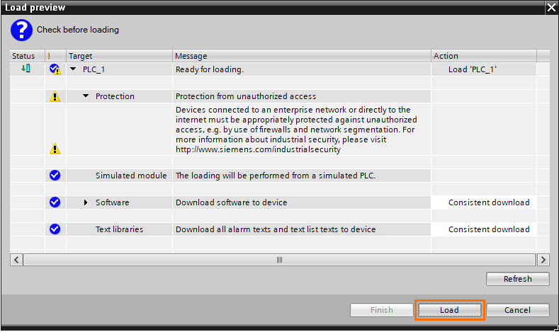
Accept any security notification that may appear then, when the load preview appears, click on “Load.”
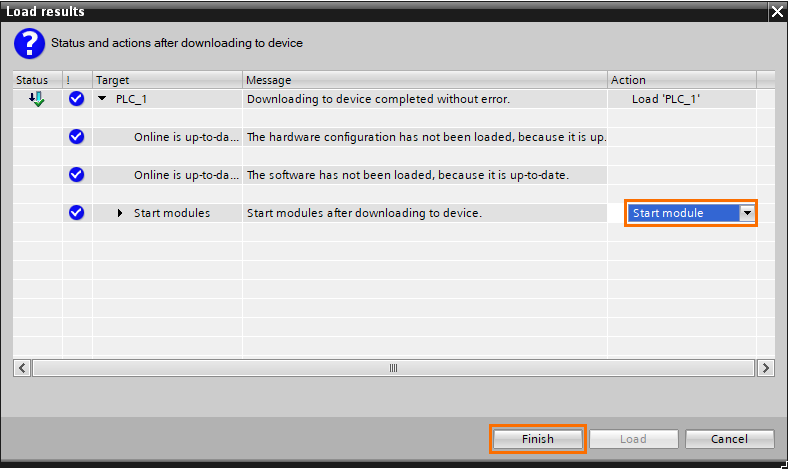
Once done, select “Start module” in the action column and click on finish.
The program on PLC_1 is loaded. Select PLC_2 in the project tree and click on the “Download to device” button.

Same operation as for PLC_1 but this time, type the IP address of PLC_2. and proceed with the rest, as shown with PLC_1.
Once done, both programs have been loaded to their proper PLC. You should have both your PLCs in RUN mode.
We will interact with the programs using online monitoring. Open the main program and the data block of each PLC and activate monitoring in each window by clicking on the “Monitoring On/Off” button.
To test the program, start by setting the “Connect” bit of PLC_2 to 1 since it’s the server. Then, do the same for PLC_1.
After that, set the “Send” bit of PLC_1 to 1. You should see the “Hello PLC_2 !” appear in the “Received_string” variable of PLC_2.
Then repeat this last step but the other way around. Set the “Send” bit of PLC_2 to 1, you should see the message “Hi PLC_1 !” appear in the “Received_string” variable of PLC_1.
Simulating communication with an external partner (Python TCP server)
In this part of the tutorial, we will demonstrate the capability of PLCSim Advanced to communicate with any type of partner using a TCP server created with Python. Communicating with self-made software means you can communicate with pretty much anything.
To create a TCP server, I wrote this simple Python code using the socket library (All libraries used are standard libraries already included in Python. No installations required). It creates a server socket waiting for a connection with only one single partner. When a connection is established, two threads are created: one for sending messages and the other for receiving. Allowing us to communicate in real-time with the PLC in the manner of a textual chat.
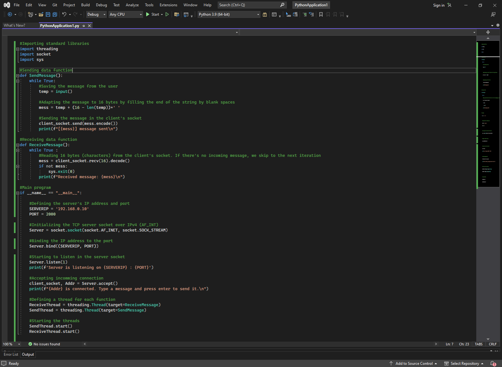
NB: You can find the code in the appendix section below.
We start by importing the needed libraries (Socket, Threading, and Sys) to summarize the code. Then we define the functions that will be executed in the threads:
- The SendMessage function continuously asks the user for the message to send, adapts it to a fixed 16 characters string, and sends it over the client socket.
- The ReceiveMessage function continuously attempts to receive 16 bytes messages. If no message is incoming, it exits its current loop iteration. (Because the “socket.recv()” method blocks the execution of the rest of the code until data is received).
We define the server in the main program (192.168.0.10:2000), create a server socket, and start listening. Then, when it receives an incoming connection, the server accepts it and starts the communication threads.
For the PLC side, we will keep the previously configured PLC_1. It’s already configured as a client and ready to use. The only difference will be in TCON’s communication block, where we need to specify the server's IP address.
Also, make sure to change the message to send in the communication DB for better clarity.
You can now update this program in the simulated PLC and start simulating. Open the main program and communication DB in monitoring mode like previously and execute the python code. Once done, set the “Connect” bit to 1 to send a connection request. You should see a message appear in the terminal telling you that a connection has been established with a partner (the IP address of PLC_1 should be mentioned).
After that, set the “Send” bit to 1 to send the previously configured message. You should see it appear in the terminal as a received message.
Then, if you type a message in the terminal, it will be sent to the PLC. You can check the communication DB for received messages.
Appendix: Python TCP server code
#Importing standard libraries
import threading
import socket
import sys
#Sending data function
def SendMessage():
while True:
#Saving the message from the user
temp = input()
#Adapting the message to 16 bytes by filling the end of the string by blank spaces
mess = temp + (16 - len(temp))*' '
#Sending the message in the client's socket
client_socket.send(mess.encode())
print(f"[{mess}] message sent\n")
#Receiving data function
def ReceiveMessage():
while True :
#Reading 16 bytes (characters) from the client's socket. If there's no incoming message, we skip to the next iteration
mess = client_socket.recv(16).decode()
if not mess:
sys.exit(0)
print(f"Received message: {mess}\n")
#Main program
if __name__ == "__main__":
#Defining the server's IP address and port
SERVERIP = '192.168.0.10'
PORT = 2000
#Initializing the TCP server socket over IPv4 (AF_INT)
Server = socket.socket(socket.AF_INET, socket.SOCK_STREAM)
#Binding the IP address to the port
Server.bind((SERVERIP, PORT))
#Starting to listen in the server socket
Server.listen(1)
print(f'Server is listening on {SERVERIP} : {PORT}')
#Accepting incoming connection
client_socket, Addr = Server.accept()
print(f"{Addr} is connected. Type a message and press enter to send it.\n")
#Defining a thread for each function
ReceiveThread = threading.Thread(target=ReceiveMessage)
SendThread = threading.Thread(target=SendMessage)
#Starting the threads
SendThread.start()
ReceiveThread.start()
Conclusion
This tutorial taught you how to simulate PLC communications using PLCSim Advanced.
Thanks to the simple interface of PLCSim Advanced, simulating communications has never been this simple. The only additional steps required are activating the virtual network adapter and creating a second PLC instance. Anything else will be creating your program and loading it.
Also, the possibility of communicating with a program we made ourselves ensures that we can make our simulated PLC communicate with anything. This dramatically expands the field of applications that can be simulated without resorting to actual hardware.
