Using Event Tables and Simulating your HMI with PLCSim

Introduction
PLCSim is a powerful tool included in TIA Portal. It can be used to simulate any type of PLC program. We previously studied how to perform simple simulations, but there are still other features to cover. Mainly the event tables. This feature allows you to simulate hardware events in your program to check its behavior when they occur. For example, you can test the execution of the Organization Blocks associated with the event.
Another feature present in TIA is the ability to simulate HMI and interface it with PLCSim. In addition to simulating HMI programs, you can connect the simulated HMI to PLCSim, allowing you to simulate your project as if it was an actual system.
In this tutorial, you will learn how to use the event tables and test the execution of their associated OBs. You will also learn how to simulate your PLC-HMI interactions using PLCSim.
Prerequisites
To follow this tutorial, you will need:
- An installation of TIA Portal. We will use TIA Portal v17, but you can use any other version. No additional hardware or software is required.
- A basic understanding of PLCSim.
Using event tables in PLCSim
Event tables are used to simulate hardware events such as rack failures, modules being unplugged, etc. When a hardware event happens, the CPU executes the content of its associated Organization Block (OB). The CPU goes into STOP mode if the OB doesn’t exist in the program. Being able to simulate these kinds of events makes it easier when it comes to programming the system’s behavior when they occur.
You can simulate four (4) types of events:
- Hardware interrupts (OB 40 to 47): These events are associated with a physical input (Possible only with modules that include this feature). Once it detects a rising or falling edge, it triggers its associated OB. This event has a high execution priority. It is mainly used to trigger emergency stops bypassing all other program executions.
- Diagnostic error interrupts (OB82): Modules with the diagnostic feature can detect when an electric failure (like power losses, short-circuits …etc) happens. Then, it executes the content of OB82. You can find information about the event in OB82’s interface.
- Pull or plug of modules (OB83): The CPU can detect whether a module has been pulled or plugged from the rack. When it happens, it executes the content of OB83.
- Rack or station failure (OB86): Similar to pulling/plugging modules, when a failure occurs in a local rack or a peripheral device, it is detected by the CPU, and it executes the content of OB86.
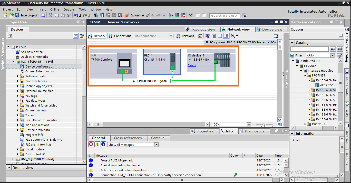
Let’s start by creating a new project. We will use a CPU 1511-1 PN in a network with ET200SP (IM 155-6) and a TP900 HMI.
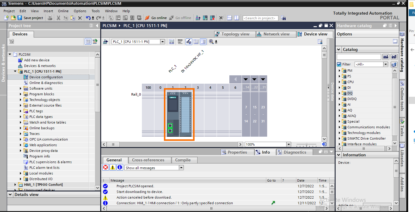
And a DI 16x24VDC HF module in the CPU rack.
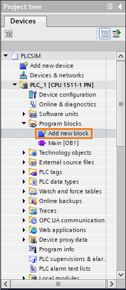
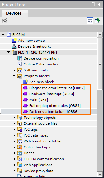
Then, click on “Add new block” in the project tree.
Then open the “Organization block” tab and select “Hardware interrupt”. Then, click “OK.”
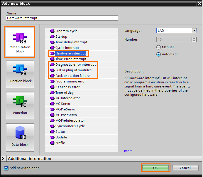
Repeat this last step to create “Diagnostic error interrupt,” “Pull or plug of modules”, and “Rack or station failure” OBs.
Then, we need to check the hardware identifiers of the DI module and the ET200. We’re going to need them later in the tutorial. After selecting the device, you can find them in the “System constants” tab.
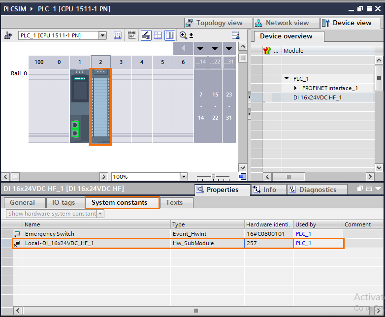
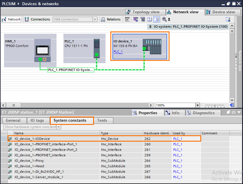
The hardware ID of the DI module is 257 and 262 for the ET200.
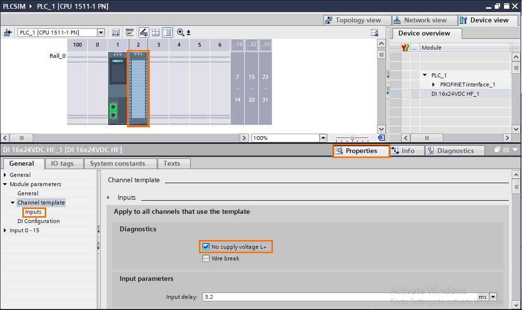
After that, we need to configure the diagnostic and hardware interrupt in the DI module. First, open the properties of the DI module, then go to the “inputs” tab and check the “No supply voltage L+” box. This will activate the power diagnostic event.
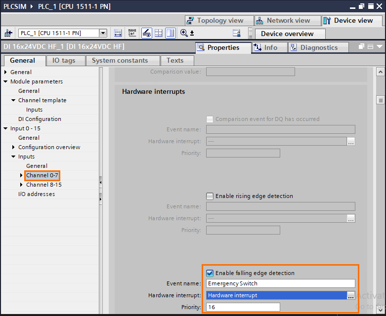
We also need to activate the hardware interrupt. To do it, open the “inputs” tab and click on “Channel 0-7,” and scroll down to the “Hardware interrupt” section of channel 0. Then, check the “Enable falling edge detection”, give a name to the event, and select OB40 in the “Hardware interrupt” section. The hardware interrupt has been configured to detect a falling edge on channel 0. For example, It is mainly used for safety loops.
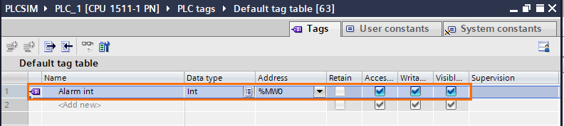
Now we must program the OBs we created. We will use a memory tag (defined as an integer) as an alarm word. If an event OB is executed, it will set a certain bit of the alarm word.
Then program the four OBs as follows:
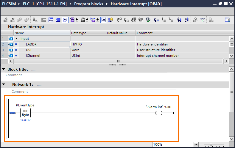
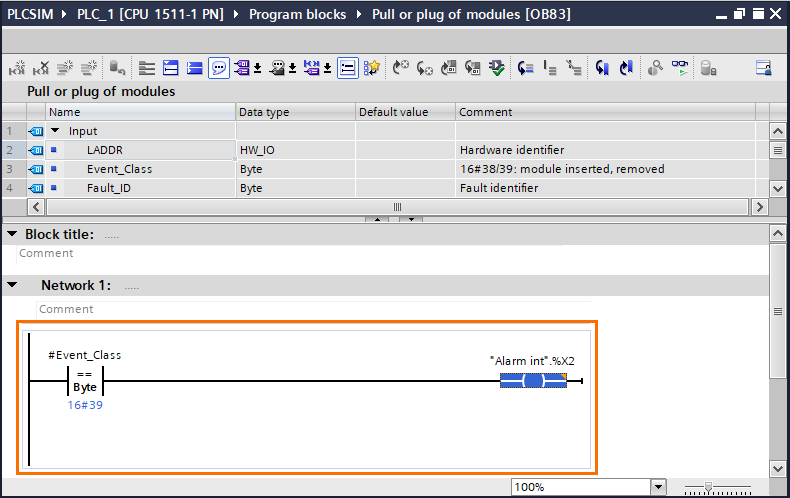
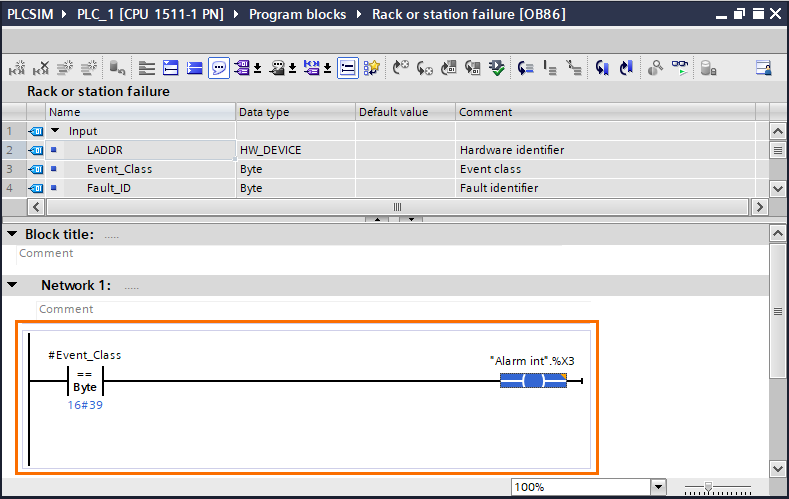
In this program, we compare the value of the input containing the error's code with the code it should have. Then assign it to a bit of “Alarm int.” This will indicate the execution of the OBs by checking the bits of “Alarm int.”
- Hardware interrupt (OB40): If the input “EventType” equals 16#02 (in hexadecimal), the bit 0 of “Alarm int” is set to 1.
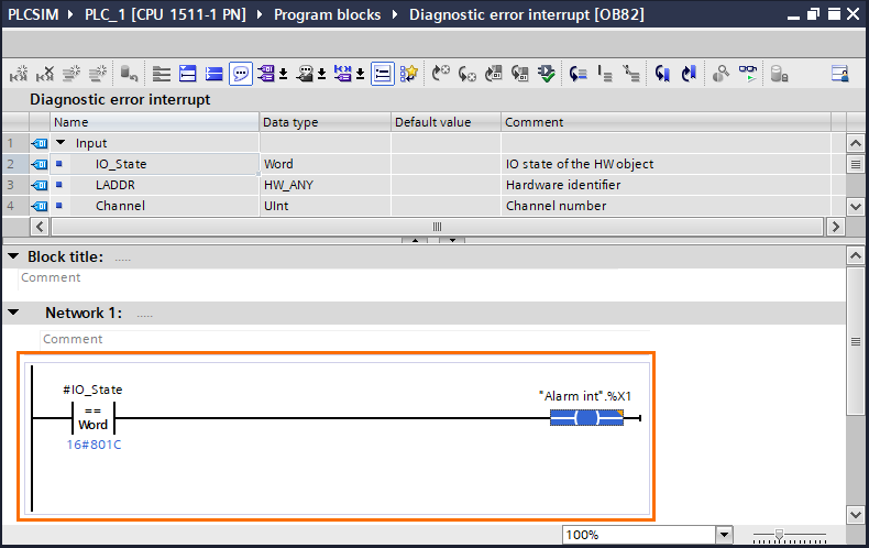
- Diagnostic error interrupt (OB82): If the input “I/O state” equals 16#801C, the bit 1 of “Alarm int” is set to 1.
- Pull or plug of modules (OB83): If the input ‘EventClass” equals 16#39, the bit 2 of “Alarm int” is set to 1.
- Rack or station failure (OB86): If the input ‘EventClass” equals 16#39, the bit 3 of “Alarm int” is set to 1.
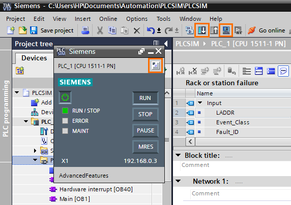
All preparations are done, we can start simulating. Open the simulator by clicking on the “Start simulation” button. Then, load your programs into the simulated PLC with the “Download to device” button. Once your program is loaded, open the simulator’s project view with the “Open project view button.”
Once in the project view, create a new project by clicking on the “New project” button.
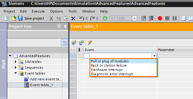
Next,open the default event table, and click on “Add new event’ scroll.
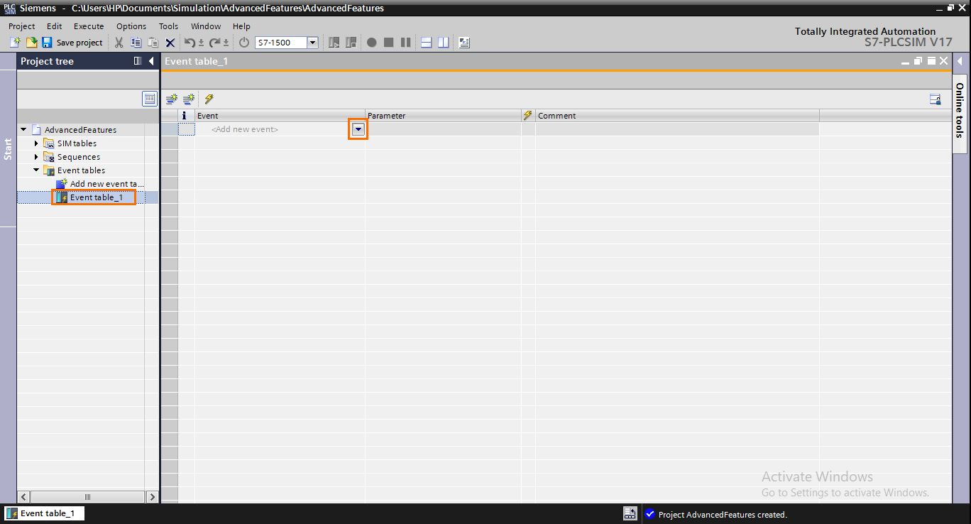
Create four events, one for each option available.
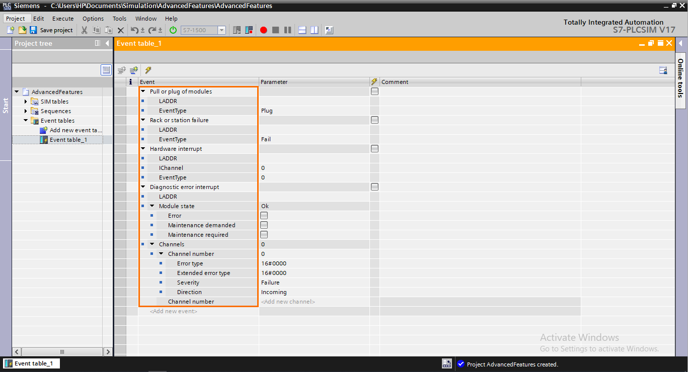
You should notice that every event has multiple parameters defining the type of error. The “LADDR” parameter, common to all events, contains the hardware identifier of the faulty module.
Edit the parameters as shown below. Then, you can execute an event by checking its associated check box and clicking on the “Trigger selected event” button.
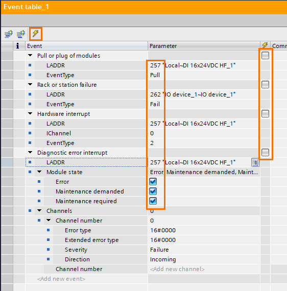
The Hardware interrupt, Diagnostic error interrupt, and Pull or plug of modules events can be used with any compatible hardware. We’re using them with the DI Module (Hardware ID 257). However, the Rack or station failure can only be used with compatible peripheral devices. So we’re using it with the ET200 (Hardware ID 262).
Lastly, you can check the execution of the OBs by using a SIM table or the CPU’s diagnostic buffer.
Simulating your HMI with PLCSim
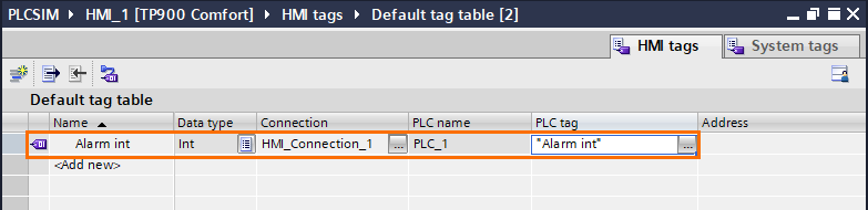
TIA Portal can simulate both PLCs and HMIs. And it is possible to connect PLCSim to the simulated HMI, which is handy for testing the interactions between PLC and HMI. For this section, we will program alarms for each event OB and display them in the HMI using HMI alarms. To do this, we first need to connect the HMI to PLCSim. The easiest way to connect the HMI and PLCSim is to link an HMI tag to a PLC tag. It is essential to keep PLCSim active during this operation. As long as it’s active, TIA Portal considers it as an actual connected PLC. Create a new HMI tag, give it a name and click on the “...” button in the “PLC tag” column. Then select the “Alarm int’ tag located in the PLC tags.
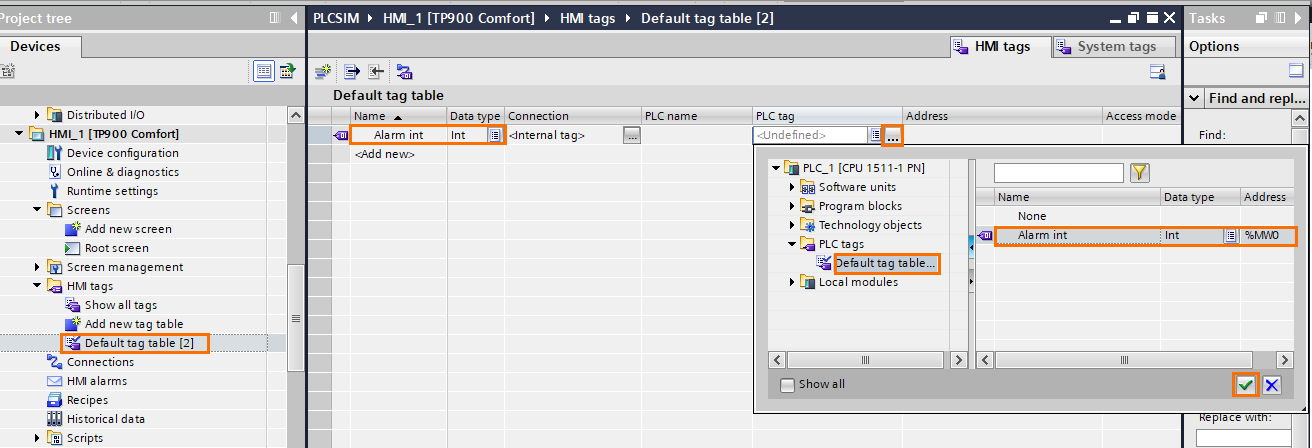
This will automatically create with PLCSim. It appears in the “Connection” column (HMI_Connection_1).
After this, open the “HMI alarms” in the project tree, create four alarms (one for each OB), and configure them as shown below.
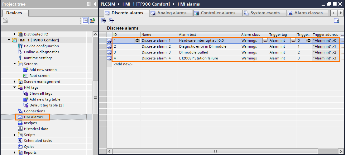
We this setting, If the “Hardware interrupt OB40” is executed, it will trigger alarm 1. If the “Diagnostic error interrupt OB82” is executed, it will trigger alarm 2. If the “Pull or plug of modules OB83” is executed, it will trigger alarm 3. If the “Rack or station failure OB86” is executed, it will trigger alarm 4.
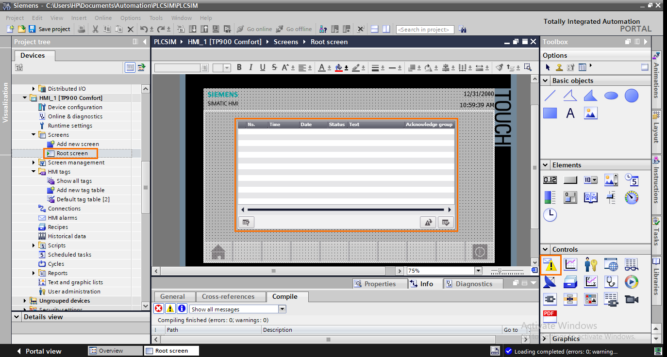
Then, to display these alarms, add an “Alarm view” element to the main screen.
Finally, open the HMI simulator by clicking on the “Start simulation” button. Then you can trigger events in the event table in PLCSim and watch them appear in the HMI simulator.
Conclusion
This tutorial taught you how to use more advanced features in PLCSim. The event tables are a powerful tool for simulating particular cases like hardware events. Without it, you would have to perform your tests over actual devices. Saving time and money for your project.
In addition, its ability to communicate within TIA Portal environments makes its use even more interesting. You can test and check the behavior of your whole system without moving from your desk.
However, some applications cannot be simulated using only PLCSim. Like simulating Ethernet communications with other devices. For this, you would have to use the more powerful version of PLCSim, namely PLCSim Advanced. This version is not included in TIA Portal and must be installed aside. This will be the subject of the upcoming tutorials.
