Allen-Bradley PointIO Safety Modules Wiring and Programming Tutorial

Introduction
Allen-Bradley’s (AB) remote PointIO offers robust flexibility for control systems. With a small physical footprint, PointIO provides interconnection for automated areas that communicate over Ethernet/IP, DeviceNet, and ControlNet. A big asset to PointIO is its safety modules.
Safety PointIO modules, such as 1734-IB8S and OB8S, provide a direct wire, safety-rated contact for devices such as emergency stops, pull-cords, and light curtains. Having these devices directly on the PLC network allows you to utilize them in the safety routines of Studio5000 programs, provides visual feedback for engineers and maintenance technicians within the program, and helps eliminate those pesky safety relays.
In this tutorial, we will be discussing the 1734-IB8S & OB8S safety PointIO modules and will learn how to configure and program them in Studio5000.
Safety PointIO Hardware Overview & Wiring
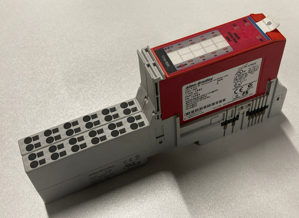
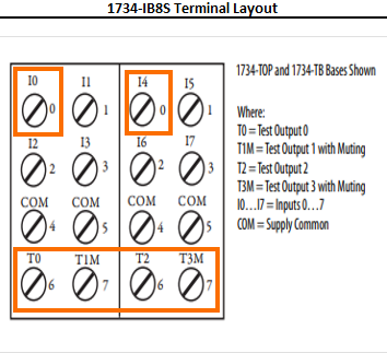
The 1734-IB8S and OB8S are 8-point modules for their respective inputs or outputs. Looking at these modules we notice they have 16 channels available with similar wiring schemes. However, the difference is in the test points on the 1734-IB8S safety input module. The 1734-IB8S first channel is input 0 or labeled as I0 on diagram 1.2. Both of the noted safety modules require two terminal bases, 1734-TOP. That is why the terminal layout below is documented with two channels as 0 (highlighted in diagram 1.2).
Channels four and five are supply commons. Channels two, three, six, and seven are important for wiring up safety devices and configuring the modules within Studio5000. The noted channels are test points, specifically test outputs. We will go into further detail on configuring inputs and test outputs later in the tutorial.
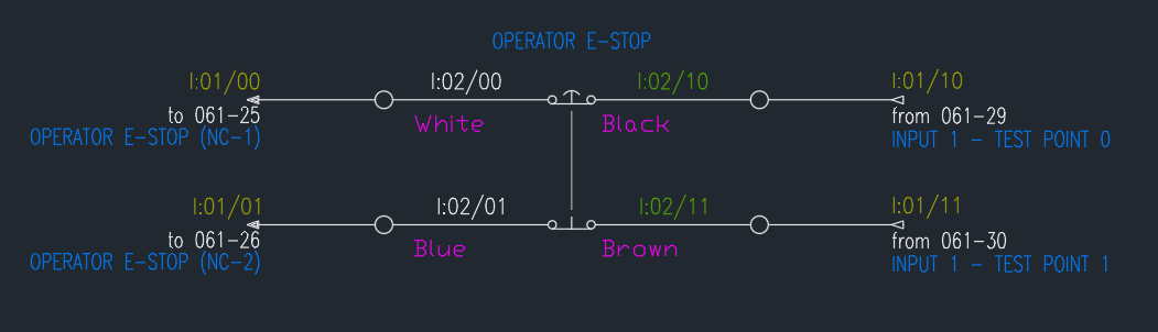
In this tutorial, we will learn how to wire an emergency stop (estop) button to the 1734-IB8S module. The emergency stop is dual channel, normally closed. This means that for wiring and programming it, we will need two channels – channel A and channel B. Input 00 will be estop channel A and input 01 channel B. Channel A will be wired so that test point 00, channel 6 (highlighted on diagram 1.2) will be wired to one side of the emergency stop’s channel A contact. The other side will have a wire coming back to the 1734-IB8S module and landing on input 00, channel 0. The emergency stop contacts are only passing a voltage through, so which side the wires are landed on does not matter. However, it is good practice to set a standard and follow it. For example, we can make sure that the input going back to the PointIO module is always on one side of the emergency stop contacts and the corresponding test point on the other. Below is an AutoCAD wiring diagram where we can see channels 10 and 11 test output channels T0 and T1 on diagram 1.3
With the emergency stop button wired up, we will move into Studio5000, configuring the safety modules and programming a small safety routine that will enable systems safety circuit and empower a variable frequency drive’s (VFD) safety torque off (STO) signal.
Configuring the Safety PointIO Modules in RSLogix/Studio 5000
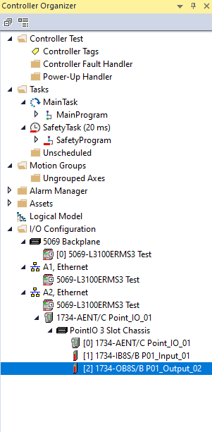
In diagram 1.4, you can see that we created a controller tree with our PointIO modules utilizing the 1734-AENT PointIO network adapter for communication back to the 5069 PLC. If you need a refresher on the controller organizer window or Studio5000 in general, read this programming RS5000 tutorial.
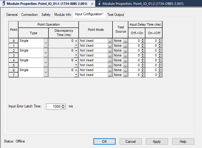
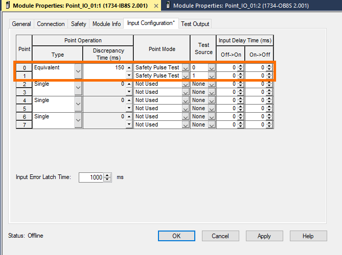
Next, either double-click on the IB8S module or right-click and select Properties (Alt+Enter). Diagram 1.5a shows the safety input module’s default configuration. For the emergency stop button, we will change the Point Operation – Type to Equivalent. This means that both points, 00 and 01, will be evaluated as a pair, based on the discrepancy time. The discrepancy time has been changed to 150ms, which allows for a small buffer for the PLC to recognize which state both channels A and B, or points 00 and 01 respectively, signals are in. The point mode should be set to Safety Pulse Test, configuring the module so that the input participates in safety evaluation and has a dependency on the test output pulse – noted with a green square in Diagram 1-5b. The Test Source configuration values range from 0-3. Our selection for this project is 0 and 1 which correlates to T0 and T1 in the terminal layout diagram.
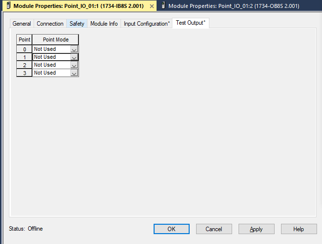
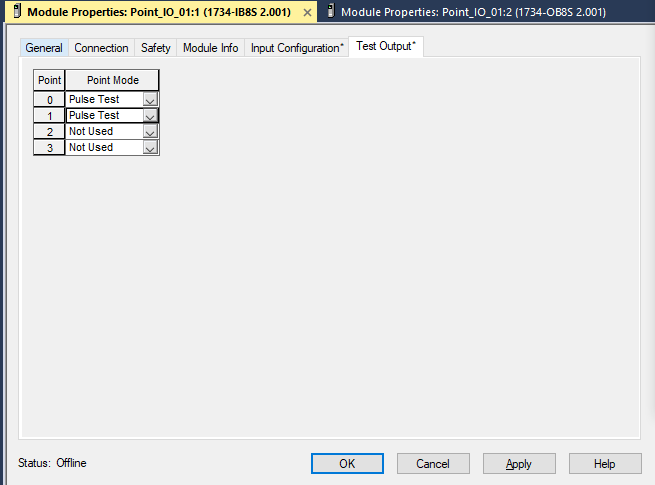
The next tab, Test Output, is where we will make our final changes for configuring the IB8S module. The default values are set to Not Used, but we want to select Pulse Test. After changing Points 0 and 1 to Pulse Test apply the changes. Note that this configuration change is vital because without it the IO module never emits a signal to the normally closed estop contacts.
Before jumping into the programming aspect of this tutorial, we will also configure the 1734-OB8S mentioned earlier and seen in the controller organizer tree.
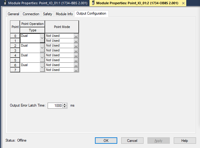
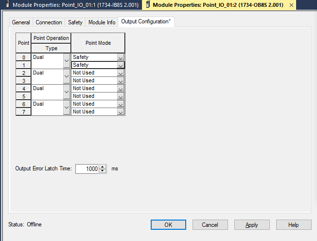
The output module does not have an input configuration or test output tab. The alterations take place on the Output Configuration tab. The default Point Operation – Type and Point Mode setting for our OB8S module are Dual and Not Used. If the default configuration is not changed then the result is that if an OTE bit goes high for output 00 the 0B8S module will never energize that point. Therefore, we will change the Point Mode of 00 and 01 to Safety. The Pointer Operation – Type could be changed to Single here, but since both of the outputs are going to the same VFD they can be left in Dual for this instance.
We will use these points for a VFD’s dual-channel STO signals later in the program. Make sure to apply the changes before moving on.
Programming a Safety Routine in RSLogix/Studio 5000
After the modules are configured, we can add two routines underneath the default Safety Program within our Studio5000 program. One will be named Emergency_Stops and the other VFD_Safety. Will begin programming within the Emergency_Stops routine for the safety circuit.
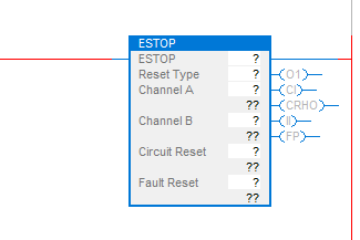
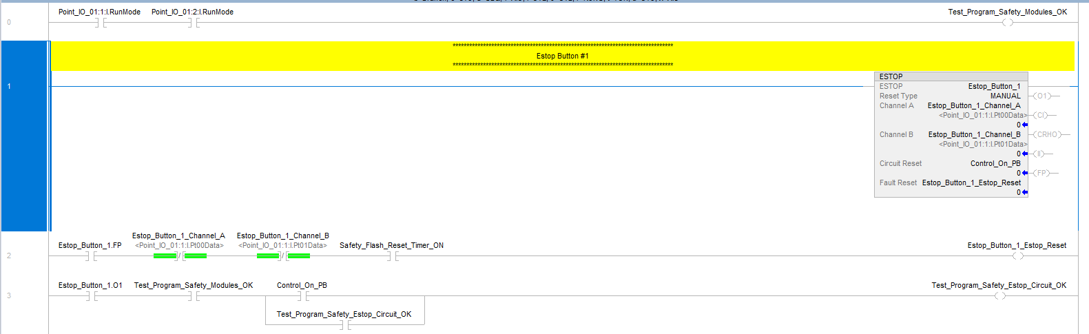
Start by adding an additional rung into the routine, and on rung 1 add the ladder element ESTOP. This presents a programming block to utilize for our dual-channel emergency stop button. The ladder element’s ESTOP operand tag is significant to that singular ladder element and should not be used anywhere else unless calling one of its sub-operands (such as Estop_Button_1.FP). The Reset Type available is Manual and Automatic. The manual reset type corresponds to a ‘hard’ reset that must occur – coming from within the PLC. This can be a pushbutton reset to the PLC or an internal PLC reset within the logic, at the discretion of the programmer and the application in question. The automatic reset instantly resets the ESTOP ladder element Fault Present operand when channels A and B are satisfactory. ESTOP ladder elements Channel A and Channel B are normally open inputs we’ve aliased to the IB8S input terminals 00 and 01 respectively. Circuit Reset operand requires a tag, but if the Reset Type is automatic, it is visual-only and not applied for resetting the ladder element. If the Reset Type is manual then this bit will reset the ESTOP ladder element after the emergency stop button has been activated and cleared (pulling a push-pull estop outwards to engage the normally closed contacts). Fault Reset will clear the ESTOP element’s fault conditions, but only after the inputs (channel A and B) have transitioned from off to on.
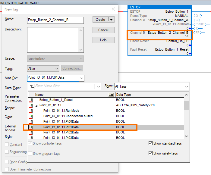
The ESTOP ladder element backing tag will be set to ESTOP_Button_1, and the rest of the block will follow a standard naming convention as seen in diagram 1.9. Note that channel A and B’s tag elements will be aliased to the 1734-IB8S points configured earlier.
When selecting the inputs be sure to utilize the module’s input data Boolean (BOOL). The IB8S modules have an input status BOOL and additionally a group of outputs test data Booleans.
Implementing another rung, rung 2, we add the following ladder elements - two XIOs, XICs, and an OTE.
The first XIC will be the ESTOP ladder element’s fault path operand, whose tag is Estop_Button_1.FP. The next two ladder elements are XICs. Both are the ESTOP operands channel A and B, following the standard tag name we insert Estop_Button_1_Channel_A and Estop_Button_1_Channel_B respectively. The last XIO is a Boolean bit that is monitoring a flash-timer add-on instruction (AOI) for when its OTE is high. This is being utilized to always fault reset the ladder element when a fault is actively present and both emergency stop channels are okay.
If you want to learn more about add-on instructions, you can read this introductory tutorial.
Next, we will add another rung, rung 3. On this rung, we will generate a safety circuit for the product for our control system.
On rung 3 we have the following ladder elements - four XIOs and an OTE.
The first XIO will reference the ESTOP elements output 1 operand. The tag for this will be set to Estop_Button_1.O1. The next XIO, Test_Program_Safety_Modules_OK in diagram 1.10, monitors something not yet mentioned.
Rung 0, referencing diagram 1.10, is monitoring the run mode status of our two safety modules. If the modules are clear of faults and actively running then both XICs will pass the rung circuit through to the OTE. This sets the OTE, Test_Program_Safety_Modules_OK, a bit high. Monitoring these modules as part of our safety circuit okay requirements allows the system to open if they fail.
Moving onto the next XIC, Control_On_PB. This bit is a field pushbutton added to turn on or enable the system’s control circuit. When this pushbutton is pressed, and if both the emergency stop’s channels are okay, then the OTE bit Test_Program_Safety_Estop_Circuit_OK is set high. The branched XIC monitors the OTE, and when energized will latch itself on around the Control On push button bit. In turn the safety circuit remains on until the emergency stop pushbutton is pressed.
The PLC logic now has a safety circuit based on our field emergency push button.
The last step of the tutorial is to program our safety outputs to enable the VFDs STOs.
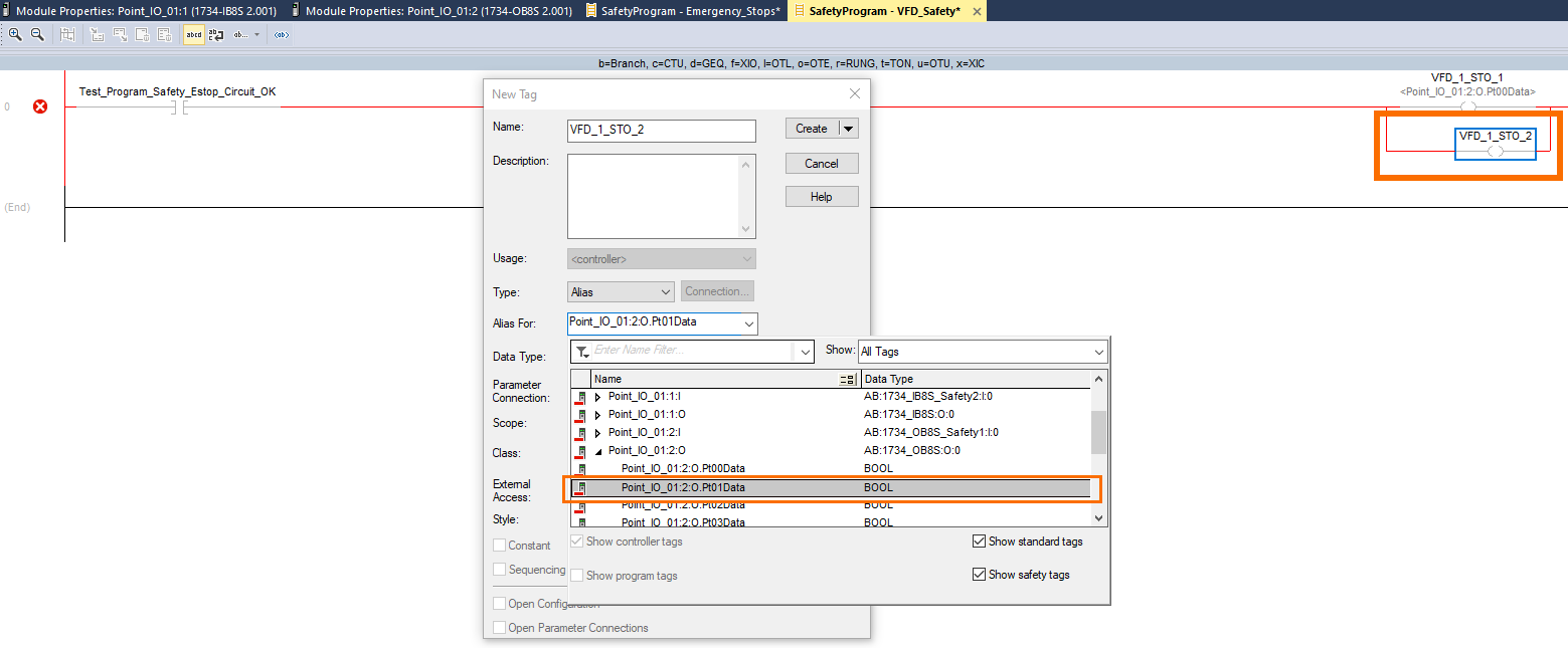
Moving over to the VFD_Safety routine created earlier, on rung 0, the following ladder elements are inserted – and XIC and two OTEs. The first XIC will reference our safety PLC’s safety circuit OTE in the Emergency_Stops routine, Test_Program_Safety_Estop_Circuit_OK. The two OTEs will be aliased to our 1734-OB8S points 00 and 01 correspondingly. Aliasing these OTEs to the module is similar to what has been done with the input module. Be sure to select the output data Booleans for the module (see diagram 1.11 for reference).
Safety Module Troubleshooting
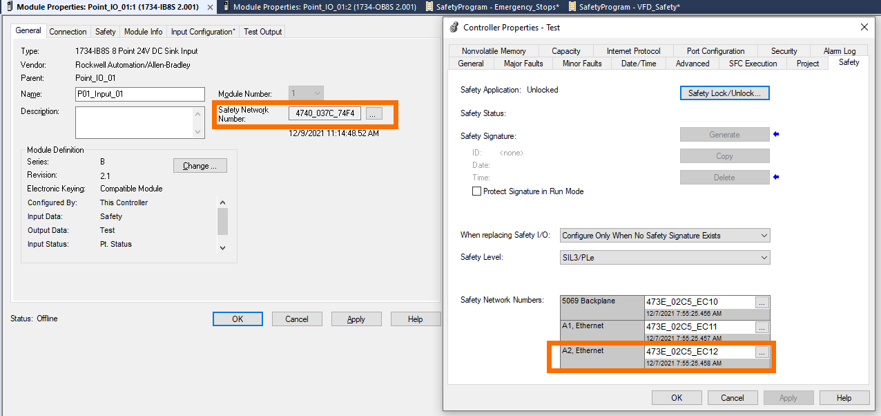
If an online safety module is faulting be sure to check the safety network number (SNN) in correspondence to the PLCs. These must match, essentially acting as a key and lock to enable the safety module from PLC to PointIO.
Reference diagram 2.0 shows that the safety network number does not match in the test programming environment. This is because it is built offline. The 1734-AENT is under the A2 network of the controller organization tree. Any safety modules ‘owned’ by the respective AENT must match the PLC’s A2 safety network number.
Conclusion
A PointIO safety circuit that controls STOs to a VFD now exists within the Studio5000 test program. Giving life to our example project, a real-world application would be a remote conveyor system with a VFD and estop. The PointIO allows for a small physical footprint and online PLC feedback visuals of what these safety devices are doing.
