Electrical Panel Wiring Diagram

Electrical panel wiring diagrams are used to outline each device, as well as the connection between the devices found within an electrical panel. As electrical panels are what will contain control systems, panel wiring diagrams are commonly encountered by PLC technicians and engineers. Although electrical panels may not be overly complex from the first glance, a lot of engineering goes into selecting proper devices, sizing wiring and designing the layout of the panel that is documented by the electrical panel wiring diagrams.
It is important to note that electrical panel wiring diagrams must follow local authorities that dictate the standards that must be respected within the panel. In the United States, this authority is the National Fire Protection Association (NFPA) and the code is called the National Electrical Code (NEC). Furthermore, each state may choose to adopt a different version of the code based on the release. It is important to be familiar with the code that applies in your area before designing a panel.
Electrical Panel - Basic Components
In this section, we’d like to start by looking at a standard electrical panel, going over the components and understanding the choices behind certain components and layout decisions.
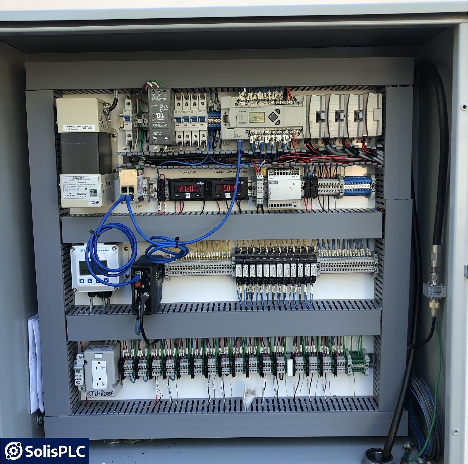
The electrical panel above includes a MicroLogix PLC, protection devices (fuses), connection devices (unmanaged switch, EtherNet to RS232 converter), terminal blocks and a power supply.
Electrical Panel Design - Power Devices
Power devices within an electrical panel are used to deliver the current required to each device and to protect them from overcurrent situations.
- Electrical Panel Circuit Breaker | Typically the entry-point for external current into the panel. An electrical panel breaker is similar to what you may found in household applications, but with much higher ratings. This device is used to cut-off all power from the electrical panel and will automatically trip when a certain current level (based on the breaker rating) is exceeded.
- Fuses | A fuse is a static device that will protect equipment and personnel from current surges. Depending on code, a fuse may be used on its own or with a combination of a breaker. When a fuse is triggered, it must be replaced before resuming operation.
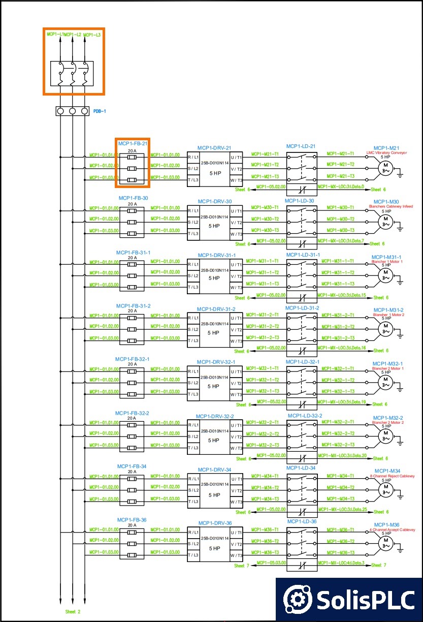
The electrical panel wiring diagram above displays an example of a circuit breaker as well as multiple fuses that protect variable frequency drives. Notice that the drawing of the circuit breaker incorporates an icon that indicates that the circuit will open during a current surge.
Electrical Panel Design - Transformers & Power Supplies
Voltage regulation is an important process within every panel. Transformers and Power Supplies are used to translate one voltage level into another. This creates a unique challenge in electrical drawings: the different voltage levels must be managed separately. Furthermore, different voltage levels will require separate terminals, fuses and wiring gages. In general, the wiring gages will be specified at the start of the drawing set. On an individual page, the voltage will be specified at the source, but rarely on each conductor. Therefore, it is important to trace back the wiring in order to confirm the source location and specifications.
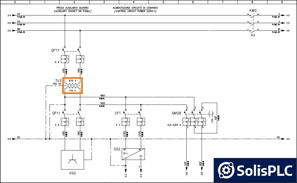
The diagram above contains a transformer that takes a 575VAC voltage and translates it into 115VAC. 115VAC is a standard voltage in North America and is utilized for many devices including PLCs, HMIs, switches and more.
A power supply will have the same function, but be indicated by a different symbol within the drawing.
As mentioned above, a voltage translation will create a new power bus. It is therefore extremely important to follow the markings and labels within the drawings in order to trace the level of voltage in question.
Electrical Panel Design - Control Devices
Control Devices are the components that will drive the process. They include programmable logic controllers, variable frequency drives, load cells, etc. In the panel we’ve mentioned above, we can identify a MicroLogix series PLC along with an array of external I/O modules. Let’s look at an example of their representation within an electrical panel drawing diagram.
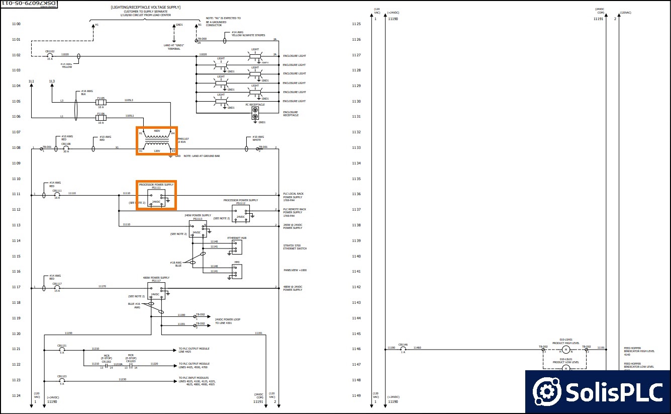
The electrical panel wiring diagram above displays an example of a transformer and a power supply used within a PLC system. It is important to note that the power supply may be a separate unit (as discussed in the previous section), or a module within a PLC rack. In addition to the power to the PLC, the wiring diagram will show the array of IO that is tied to the PLC; let’s look at an example below.
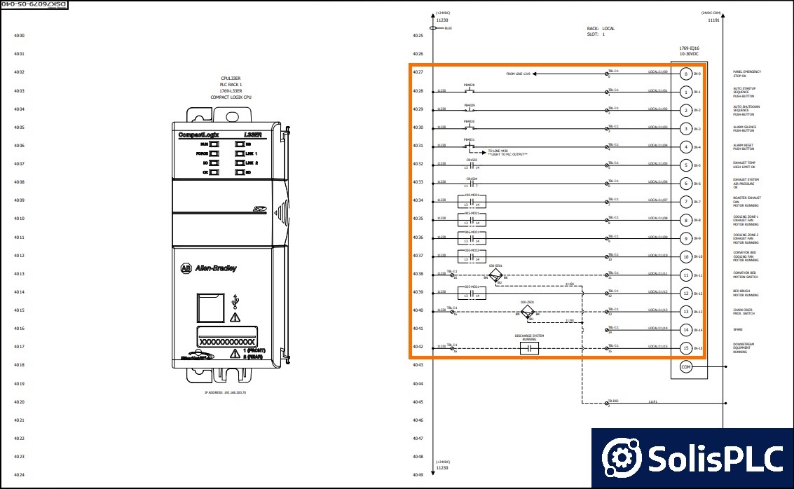
The drawing above displays the first card of the Allen Bradley CompactLogix PLC. Based on the model of the card (1769-IQ16), as well as the nature of the devices tied to each point on the card, we can immediately conclude that the card is a 24VDC 16 point Input card. The following devices are shown in the drawing:
- Input 0: “FROM LINE 1219” | A device drawn on another page of the drawing set.
- Input 1: “PB4028” | Normally Open Push-Button
- Input 2: “PB4029” | Normally Closed Push-Button
- Input 3: “PB4030” | Normally Open Push-Button
- Input 4: “PB4031” | Normally Open Push-Button
- Input 5: “CR1503” | Control Relay
- Input 6: “CR1504” | Control Relay
- Input 7: “190-MC01” | Motor Contactor
- Input 8: “905-MC01” | Motor Contactor
- Input 9: “906-MC01” | Motor Contactor
- Input 10: “030-MC02” | Motor Contactor
- Input 11: “030-SE01” | 3 Way Selector Switch
- Input 12: “035-MC01” | Motor Contactor
- Input 13: “030-ZS01” | 3 Way Selector Switch
- Input 14: N/A
- Input 15: “DISCHARGE SYSTEM RUNNING Contact”
The electrical drawing will split each card onto a page. In other words, the external modules we saw in the panel will have a separate page on which the components connected to each point are shown.
Electrical Panel Design - Electrical Device Symbols
We haven’t covered all the major components in the section above. However, since we dove into Input and Output points tied to external devices, it is important to cover those before we proceed. In this section, we will present a device symbol that you may find in an electrical panel wiring diagram and give a brief description of the device, as well as a few examples for reference.
Wiring Symbols in Electrical Drawings
Wires are what ties the devices together. Lines are used to represent the wiring of the panel. The basic lines you’ll encounter are as follows:


Basic Wire - A connection between two components.
Note: The wire becomes a dotted line once the wiring is external to the panel described by the drawing.


Wire Junction - A connection between multiple conductors.


Wire Bypass - No current bypass of two conductors. No connection is made between the horizontal and vertical conductors.
Push-Button and Switch Symbols in Electrical Drawings
Push-Buttons and Switches play an important role in manufacturing automation. They are used to receive user input as well as the state of machinery. It’s important to note that a switch does not always equate to a push button on a machine. A switch also includes a wide array of limit switches used in the process. The label above the device will typically indicate what the nature of the device is.
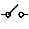


Switch - [Left] - Normally Open | [Center] - Normally Closed | [Right] - Single Pole Dual Throw (SPDT)
An electrical switch is a basic device that will conduct current when it is closed and block current from passing when it is open. The signal that is transmitted through the switch may be read by a field device or a PLC input as we saw above.
A wide array of switches are used in industrial manufacturing. We’ve written an in-depth guide on how some of these switches operate and where they are used in manufacturing in the following article: Limit Switch.
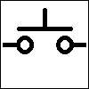

Push-Button - [Left] - Normally Open | [Right] - Normally Closed
A push button is a momentary electrical switch that will conduct current when it is closed and block current from passing when it is open. The difference between a switch and a push button is that the push button will automatically revert to the initial state while the switch will maintain the state until it is toggled.
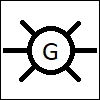
Light - [Left] - Red | [Right] - Green
A light is typically used as an indicator for the process. This may be an LED or a stack-light on the panel or an indicator on a machine or piece of process equipment.
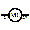
Motor Coil Contact
A Motor Coil Contact is an input of a contactor or variable frequency drive. By energizing the coil, the drive will close the required contacts and start the motor. Note that the coil also indicates the terminals on which the connections have to be landed. The orientation (+24VDC vs 0VDC) is important and will be indicated by the electrical drawing.
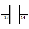
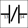
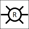
Motor or Relay Contact - [Left] - Normally Open | [Right] - Normally Closed
A contact represents the state of a certain device. When a relay is energized, a contact is either closed or opened depending on the initial state. When the contact is closed, the current flows through; when it is opened, the current is stopped. When it comes to a motor contactor, it’s good practice to send the signal back to the PLC as a confirmation that the device has been energized. Therefore, the PLC will receive a signal from the contact and confirm in logic.
Other Devices in Electrical Drawings
We’ve covered a few basic devices you’ll encounter in electrical drawings. This list is by no means exhaustive. There are a number of variations of the basic devices as well as symbols for others that you will encounter. We recommend that you refer to the manufacturers technical notes when it comes to the appropriate symbols. In most cases, they are listed in the data sheet.
Electrical Panel Design - Network Devices
Networks are a critical component in most modern panels. They host a number of various protocols such as EtherNet, DeviceNet, ProfiBUS, ControlNet, Serial and more. The difference between the representations of typical electrical panel wiring diagrams for normal wiring and network devices is that they often omit the multi conductor cabling. In other words, a standard EtherNet cable, which may contain 8 wires, will be represented as a single conductor. Let’s look at an example below.
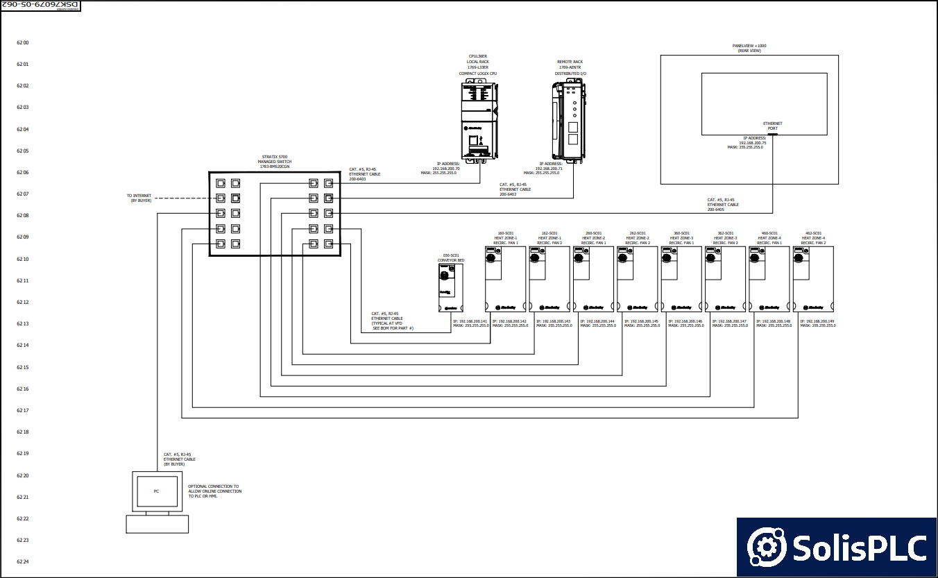
In the diagram above, we are shown a connection between an unmanaged switch and a series of peripheral devices that utilize the EtherNet protocol. As mentioned above, for simplicity purposes, it is assumed that the reader understands the use of the RJ45 standard EtherNet cable for this purpose.
Note that this page only describes network connections to these devices. The same devices will be listed on a different page as they require additional signals. Example: The “030-SC01 Conveyor Bed” Variable Frequency Drive (VFD) will be connected to power, a motor, the PLC and safety circuits. These will be covered in a separate page of the electrical panel wiring diagram.
Electrical Panel Wiring Diagram Analysis
In this section, we will review a series of pages from wiring diagrams, outline key elements, disclose which information can be drawn from each page and comment on how a specific page can be used to troubleshoot the system.
Motor Control Panel Schematic
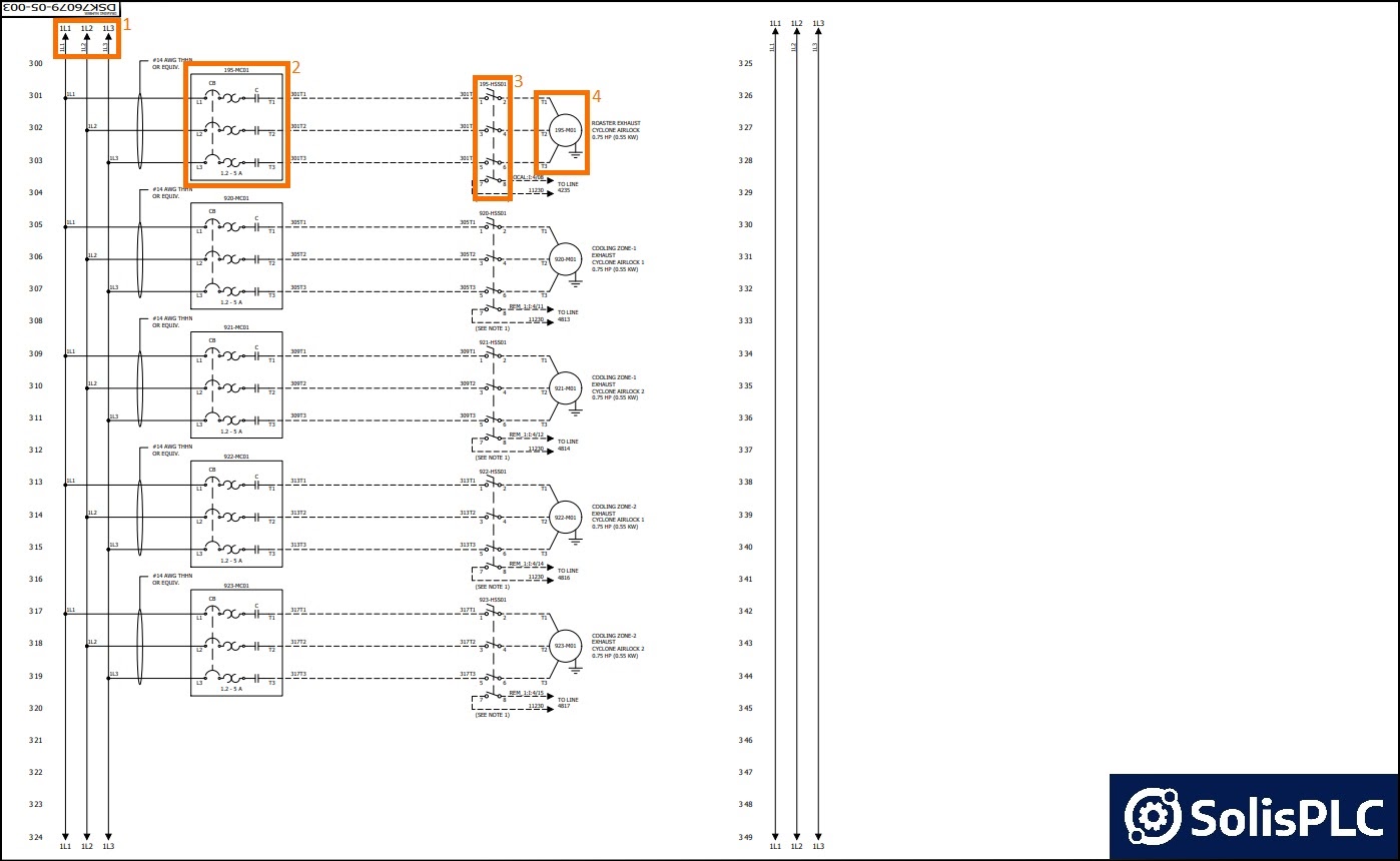
In the drawing above, we have 4 key elements:
- The entry point of the electrical bus comes from the previous page. If we navigate to the first page of our electrical drawings, we can find the specification of the voltage on the bus: 460 VAC 3 Phase 60 Hz.
- The 195-MC01 is a Motor Contactor that includes a circuit breaker, a thermal fuse and a contact. The drawing calls out the setting of the circuit breaker: 5A.
- The 195-HSS01 is a motor disconnect switch. Note that the disconnect provides a means to disconnect the high voltage from the motor, as well as feedback to the PLC. The drawing specifies “LOCAL:I:4/08” as the disconnect input into the PLC.
- The 195-M01 is a 3-Phase Motor of 0.75 HP.
Potential Troubleshooting Activities
- Tripped Motor Contactor | Refer to 192-MC01 device. Measure the voltage coming into the device to be 460 VAC, 60 Hz. Verify that the setpoint of the breaker is 5A.
- Motor Not Running | Refer to 195-M01 device. Verify that the motor disconnect switch (195-HSS01) is in the ON position. This can be done by measuring output voltage and verifying the PLC signal listed above. Verify that the motor contactor (195-MC01) is not tripped. Verify that the motor windings by measuring resistance when it is disconnected via the motor disconnect switch.
Safety Circuit Panel Schematic
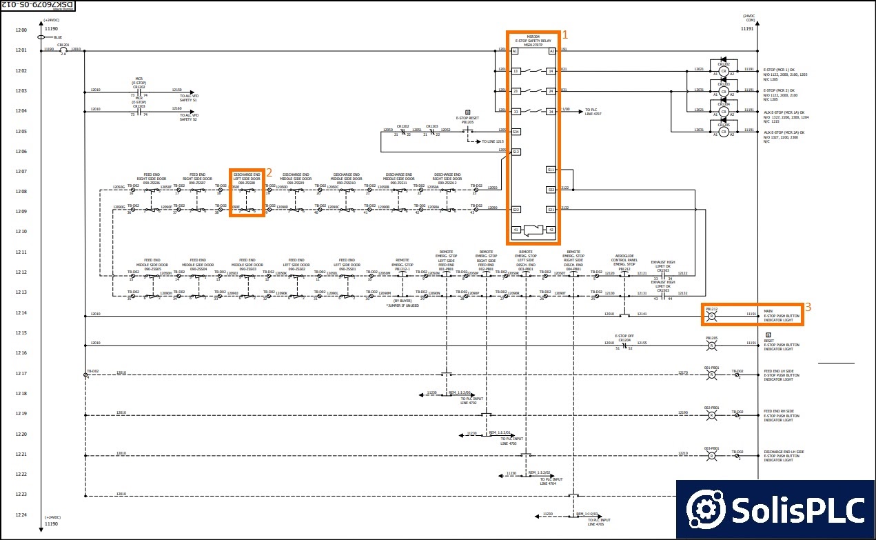
The electrical wiring diagram above contains an example of a safety circuit one may find in an industrial environment. The following components are shown here:
- The MSR304 is an Allen Bradley Safety Relay. It sends a signal through a series of safety switches and E-Stops and reads the signal it receives at the end of the chain. If all the switches are closed, the relay confirms that the safety circuit is good and energizes the load it is tied to.
- The 090-ZSS11 is a safety switch that is part of the safety chain of devices. As shown in the diagram, the safety devices are wired one after the other.
- The E-Stop Push-Button Indicator Light is the device that will indicate when the E-Stop is pressed. Notice that this signal is drawn directly from the push-button through a normally open contact. In other words, this light will only energize when the E-Stop is pressed; not any other element in the safety circuit chain.
Potential Troubleshooting Activities
- E-Stop Circuit Fault | Refer to “MSR304” Device. Start by verifying the E-Stop light. Un-press the E-Stop if it is pressed. Verify the voltage at every safety related device. The chain should return a 24VDC signal on each line. If that’s not the case, narrow down the circuit element (switch) that is causing the problem.
- Safety Circuit Not Resetting | Refer to “MSR304” Device. The same steps as the ones above will need to be performed. The relay will only reset when it receives the correct signal from the field devices. If it’s not the case, the relay won’t energize.
Electrical Panel Wiring Diagram - Software Tools
In this section, we'll outline different tools engineers and technicians use to create electrical panel wiring diagrams. Some of these tools are expensive and are sold through distributors only. However, most of these vendors provide trial versions that you can utilize with limited capabilities in order to assess if their solution is right for you.
AutoCAD Electrical by Autodesk - One of the most utilized tools within the industry. AutoCAD is a full features toolset with a wide range of features for many applications. It's an expensive license, but comes with an extensive library of devices that is constantly updated with most vendor offerings.
EPLAN - This tool specializes in design software for panel and industrial design. You won't find the extensive list of features you may see in AutoCAD, but the features you will find are exceptionally well designed and maintained by the team. EPLAN has gained in popularity in the recent years and has become the tool of choice for many engineers and electricians.
SkyCAD - This "lower-end" tool has less bells and whistles, but comes at a massive discount when compared to anything else on the market. It's an excellent solution for a smaller facility, personal user or a contractor.
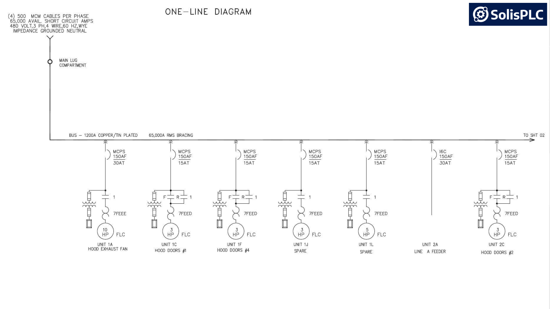
Understanding Single Line Diagrams
A Single Line Diagram (SLD) serves as a concise graphical representation of an electrical system or circuit, utilizing a single line to illustrate the connections and components involved. This diagrammatic approach proves instrumental for professionals such as engineers and electricians, facilitating a comprehensive understanding and analysis of the overarching structure within a power distribution system.
Incorporating statistical insights, recent data indicates that the implementation of SLDs leads to a notable 30% increase in troubleshooting efficiency for engineers. Electricians, similarly, report a significant 25% enhancement in operational efficiency when utilizing SLDs. These statistics underscore the substantive impact of SLDs as a strategic tool in optimizing the functionality and problem-solving capabilities of professionals in the field.
Rationale for Utilizing Single Line Diagrams
The adoption of Single Line Diagrams (SLDs) is imperative due to their ability to provide a lucid and succinct overview of intricate electrical systems. This expedites the analysis of system configuration and functionality, rendering SLDs indispensable for the design, planning, and troubleshooting of electrical installations.
Significant Advantages
Simplified Visualization - SLDs present a streamlined visual representation, facilitating a more accessible comprehension of the system's architectural intricacies.
Efficient Analysis - Engineers benefit from the rapid identification of components, connections, and potential issues, resulting in a streamlined and efficient analysis process.
Documentation - Serving as invaluable documentation for system design, SLDs contribute to effective communication among team members and assist in future maintenance endeavors. The comprehensive nature of SLDs ensures a reliable reference point for ongoing and prospective projects, enhancing overall project management.
Elements Comprising a Single Line Diagram
Power Sources
Generators, transformers, and utility connections are conventionally illustrated using standardized symbols on a Single Line Diagram (SLD). These symbols convey crucial information regarding the type and capacity of the respective power sources.
Transmission Lines
The depiction of transmission lines on the SLD involves connecting various components with lines, delineating the path through which electrical power traverses the system. Distinct line types may signify varying voltage levels or different types of conductors, contributing to a comprehensive representation.
Distribution Components
Essential elements in an electrical system, including circuit breakers, switches, and protective devices, find representation on the single line. Their placement and interconnections within the network are highlighted to provide a clear understanding of the system's functional structure.
Loads
The incorporation of loads on the diagram accounts for devices or equipment consuming electrical power. This category spans a spectrum, encompassing lighting fixtures, motors, and entire industrial processes. The representation of loads on the SLD ensures a holistic portrayal of the system's energy consumption dynamics.
Common Wiring Standards
In the intricate world of electrical systems and technology, adherence to standardized wiring practices is paramount to ensure safety, reliability, and interoperability. Three major entities play a pivotal role in shaping and maintaining these standards: the National Electrical Code (NEC) in the United States, the International Electrotechnical Commission (IEC) globally, and the Institute of Electrical and Electronics Engineers (IEEE) in various fields of electrical and electronics engineering.
National Electrical Code (NEC)
The NEC stands as the cornerstone of electrical standards in the United States. Developed and maintained by the National Fire Protection Association (NFPA), the NEC provides a comprehensive set of guidelines for the safe installation and use of electrical systems. Key aspects covered by the NEC include:
.png)
Conductor Sizing
The NEC offers detailed guidance on the sizing of conductors, ensuring that they can carry the intended electrical load without overheating.
Overcurrent Protection
To prevent fires and equipment damage, the NEC specifies methods for protecting circuits from excessive currents through the use of fuses, circuit breakers, and other devices.
Grounding
Proper grounding is crucial for electrical safety. NEC standards outline grounding requirements to minimize the risk of electric shock and facilitate the safe dissipation of fault currents.
Wiring Methods
Different applications demand specific wiring methods. NEC covers various techniques, including conduit, cable trays, and raceways, providing a roadmap for proper installation.
International Electrotechnical Commission (IEC) Standards
As a global player, the IEC sets the stage for standardized electrical and electronic technologies. IEC standards are recognized and adopted by numerous countries worldwide, fostering consistency and compatibility. The IEC's influence extends across a wide range of areas:
Wiring Practices
IEC standards establish common practices for wiring, ensuring that electrical systems operate safely and efficiently regardless of geographic location.
Equipment Specifications
From transformers to electronic devices, IEC standards define specifications to guarantee the reliability and interoperability of electrical equipment.
Safety Considerations
IEC places a strong emphasis on safety, providing guidelines for protection against electric shock, fire hazards, and other potential risks associated with electrical systems.
Institute of Electrical and Electronics Engineers (IEEE) Standards
IEEE standards span a multitude of disciplines within electrical and electronics engineering. These standards are instrumental in achieving compatibility and reliability across different technologies and applications:
Power Distribution
IEEE standards address efficient power distribution, covering aspects such as voltage levels, power factor correction, and reliability in electrical grids.
Communication Protocols
In the realm of networking and communication, IEEE standards define protocols that facilitate seamless data exchange, ensuring interoperability among devices.
Specific Applications
IEEE standards cater to specialized fields like industrial automation and building wiring, providing guidelines for the implementation of technology in these contexts.
In conclusion, the NEC, IEC, and IEEE standards collectively form a robust framework for the design, installation, and maintenance of electrical systems globally. Adhering to these standards not only enhances safety but also fosters innovation and harmonization in the ever-evolving landscape of electrical engineering. Whether you are a professional electrician, an engineer, or an enthusiast, understanding and implementing these standards is vital for creating a reliable and safe electrical infrastructure.
Q&A on Electrical Panel Wiring Diagram
What is an electrical panel wiring diagram?
Answer: An electrical panel wiring diagram is a schematic representation that outlines each device and the connections between them within an electrical panel. These diagrams are essential for understanding the layout and ensuring proper installation and maintenance of electrical systems.
Why are electrical panel wiring diagrams important?
Answer: They provide a clear roadmap of the electrical system, facilitating troubleshooting, maintenance, and ensuring compliance with safety standards.
What are the basic components depicted in an electrical panel wiring diagram?
Answer: Common components include circuit breakers, fuses, transformers, power supplies, control devices like PLCs, and various types of switches and relays.
How do I read and interpret electrical panel wiring diagrams?
Answer: Start by familiarizing yourself with standard electrical symbols and notation. Follow the wiring paths, noting connections between components, and refer to the legend or key provided in the diagram for clarification.
What are the common symbols used in electrical wiring diagrams?
Answer: Symbols represent various components such as switches, relays, motors, and connectors. For instance, a simple line may represent a wire, while specific shapes denote different types of devices.
Electrical Panel Wiring Diagram Conclusion
Electrical Drawings are mandatory by the National Electrical Code (NEC) in the US and other authorities in different regions of the world. They provide a specification list to which electricians and engineers will design and assemble the control panel used in manufacturing and the industry.
Each page of the drawing will display a circuit that will contain some of the elements of the panel along with references to other pages. By using the schematic, it’s possible to identify elements within the panel, validate the connections and troubleshoot field issues when they occur.
