Getting Started With EPLAN - How to Layout a Basic Electrical Panel Diagram

Introduction
Creating precise and efficient electrical panel diagrams is the cornerstone of every successful project in electrical engineering and industrial automation. These diagrams are the blueprint for controlling and managing electrical systems, making them an integral part of any automation or electrical design project.
EPLAN, a leading software solution in the field, simplifies the process of designing electrical panels. Whether you're an aspiring electrical engineer, a seasoned professional looking to upgrade your skills, or simply someone with a curious mind, this guide will walk you through the fundamentals of EPLAN panel design, specifically focusing on laying out a basic electrical panel diagram.
From understanding the essential concepts to mastering the tools within EPLAN, this article will equip you with the knowledge and confidence to create efficient electrical panel diagrams. So, if you're ready to embark on this exciting journey, let's dive into the world of EPLAN and explore how to craft your first electrical panel diagram.
Prerequisites
- In this tutorial, we will be using EPLAN v2024.
EPLAN – Interface
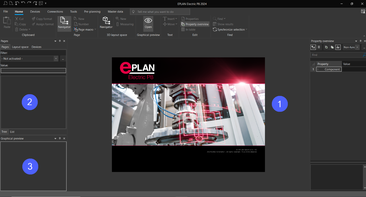
Open EPLAN, you'll notice three important key areas within the interface:
Workspace (Circle 1): This is where your project takes shape. It's the primary area where you'll create and design your projects.
Page Navigator (Circle 2): In this section, you gain a comprehensive view of all the pages in your project. It serves as a handy roadmap to navigate through your project's structure.
Graphic Preview (Circle 3): This dynamic space allows you to visualize and interact with selected elements within your project. Whether its pages, devices, or other components, you'll see them here.
Note, to hide “Page Navigator” you can do one of the following:
Press the “F12” key.
Click on the “Page Navigator Icon.”
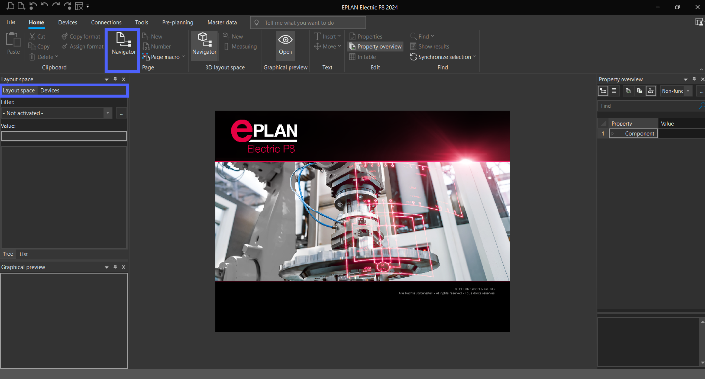
Note: we will cover the “Layout Space and Devices Navigator” in the upcoming 3D Tutorial.
EPLAN – Create New Project
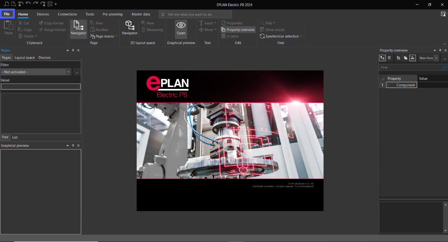
Click “File.”
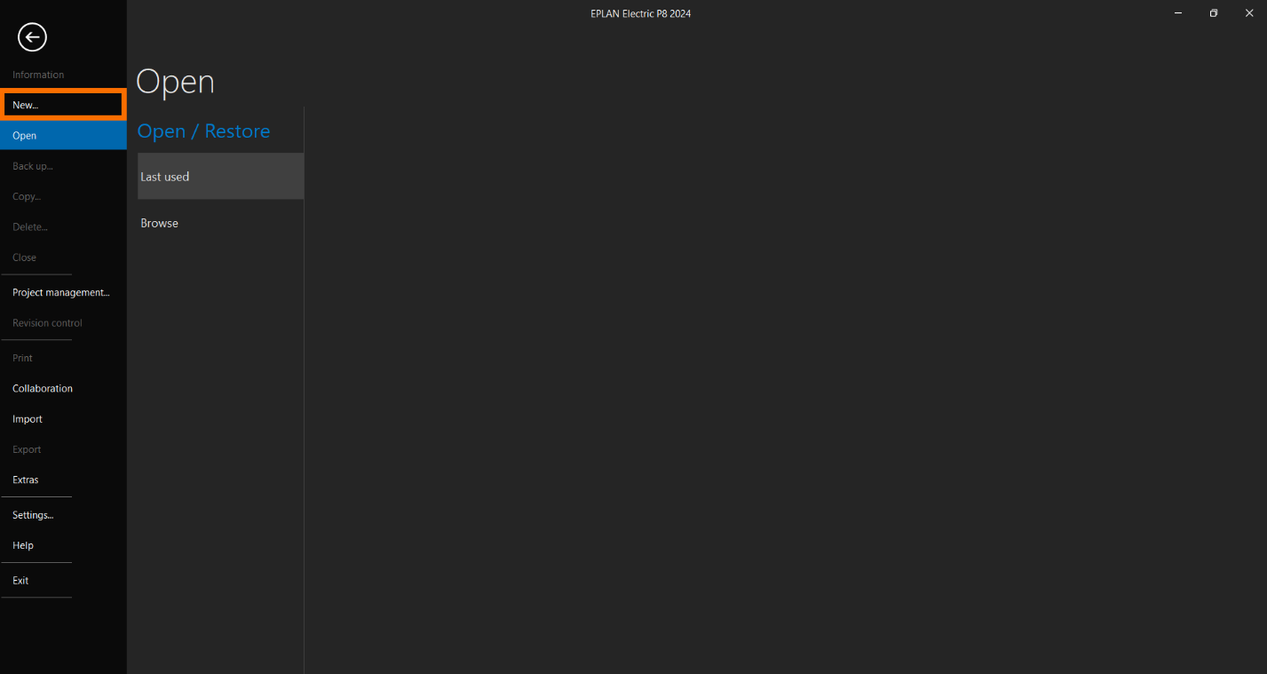
Click “New.”
Specify the “Project Name,” “Project Location,” “Creator name,” and “Date and Time” settings. Note, that “Basic project” contains a predefined project structure that includes essential templates, settings, and configurations.
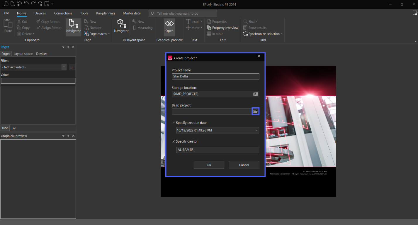
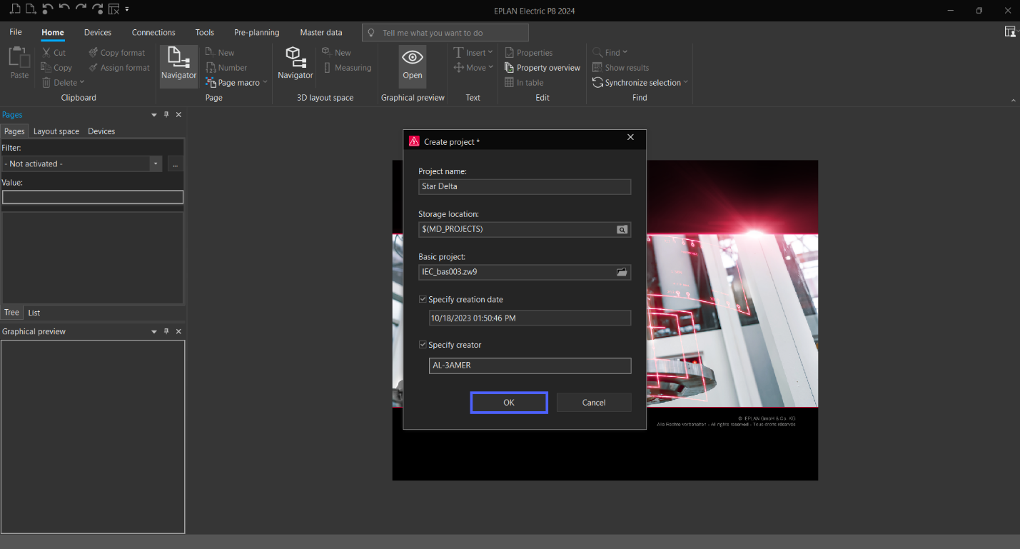
Click on “Folder icon” to add “Basic project.”

Click “OK.”
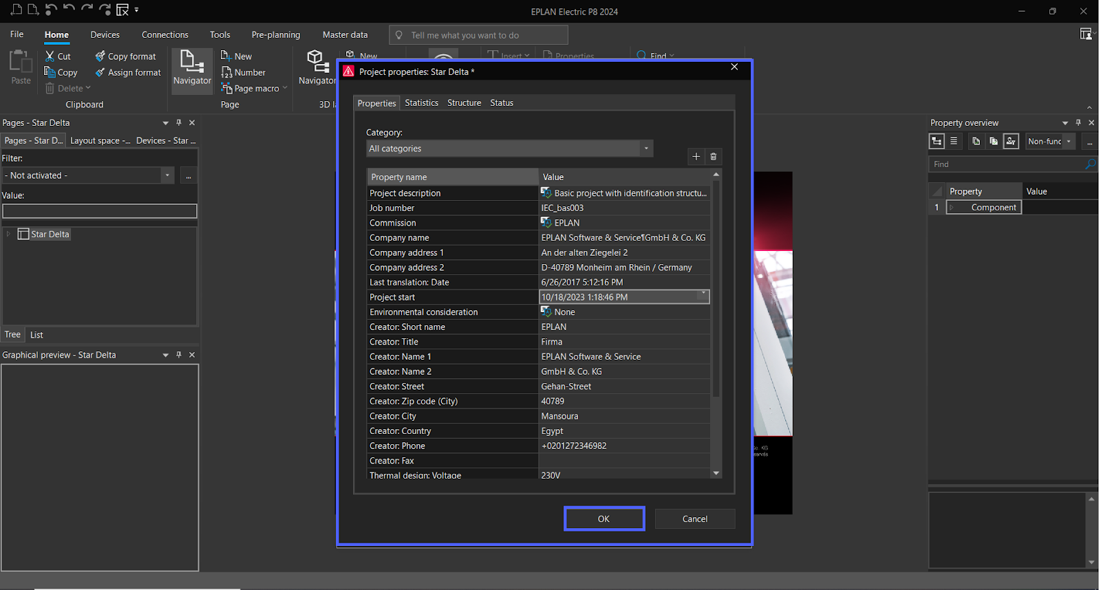
Configure your "Project properties" and then click "OK."
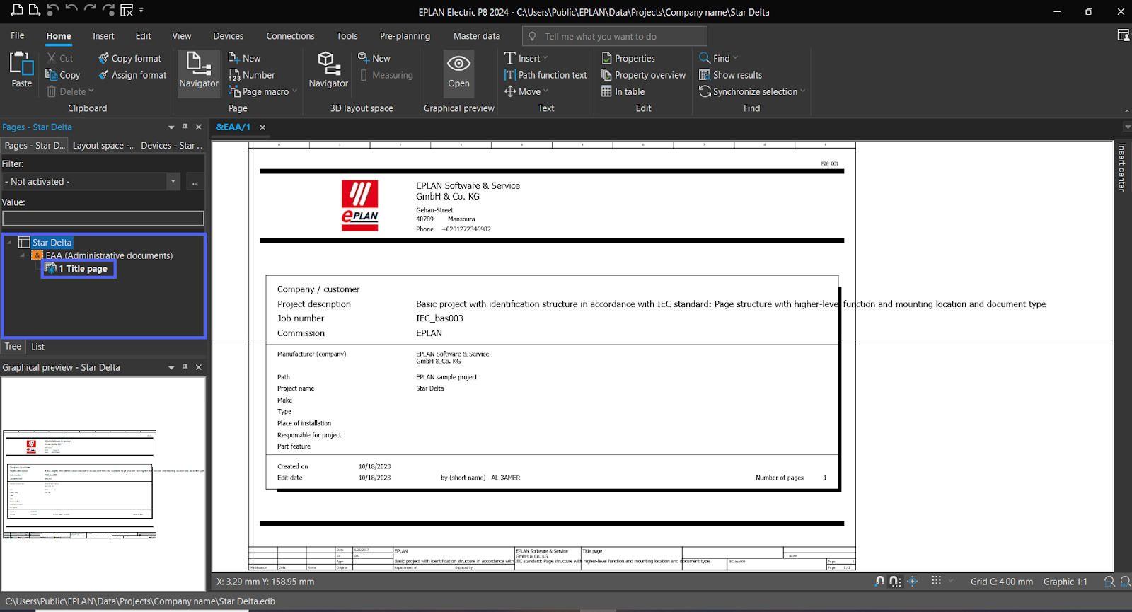
Now the project has been successfully created.
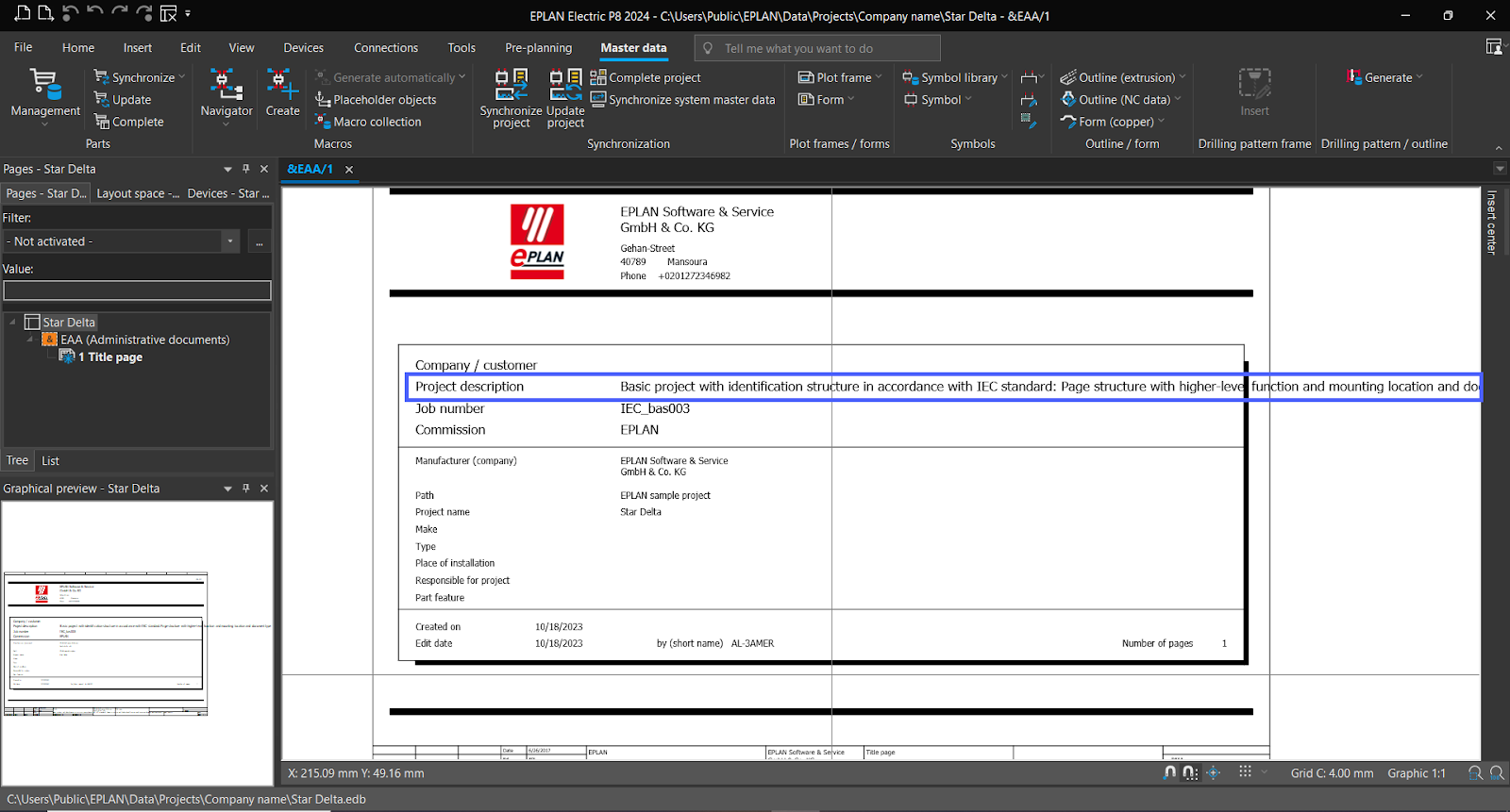
EPLAN – Edit Title Page
Let’s edit “Project Description.”
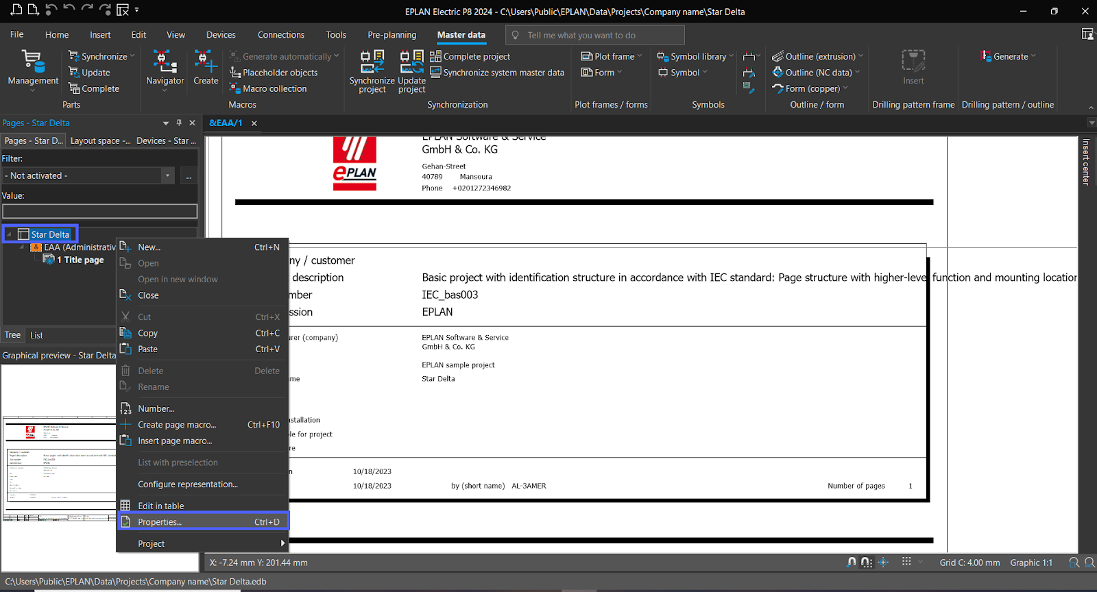
Right-click on the "Project name" and select "Properties."
In the "Project description" field, provide a description for your project.
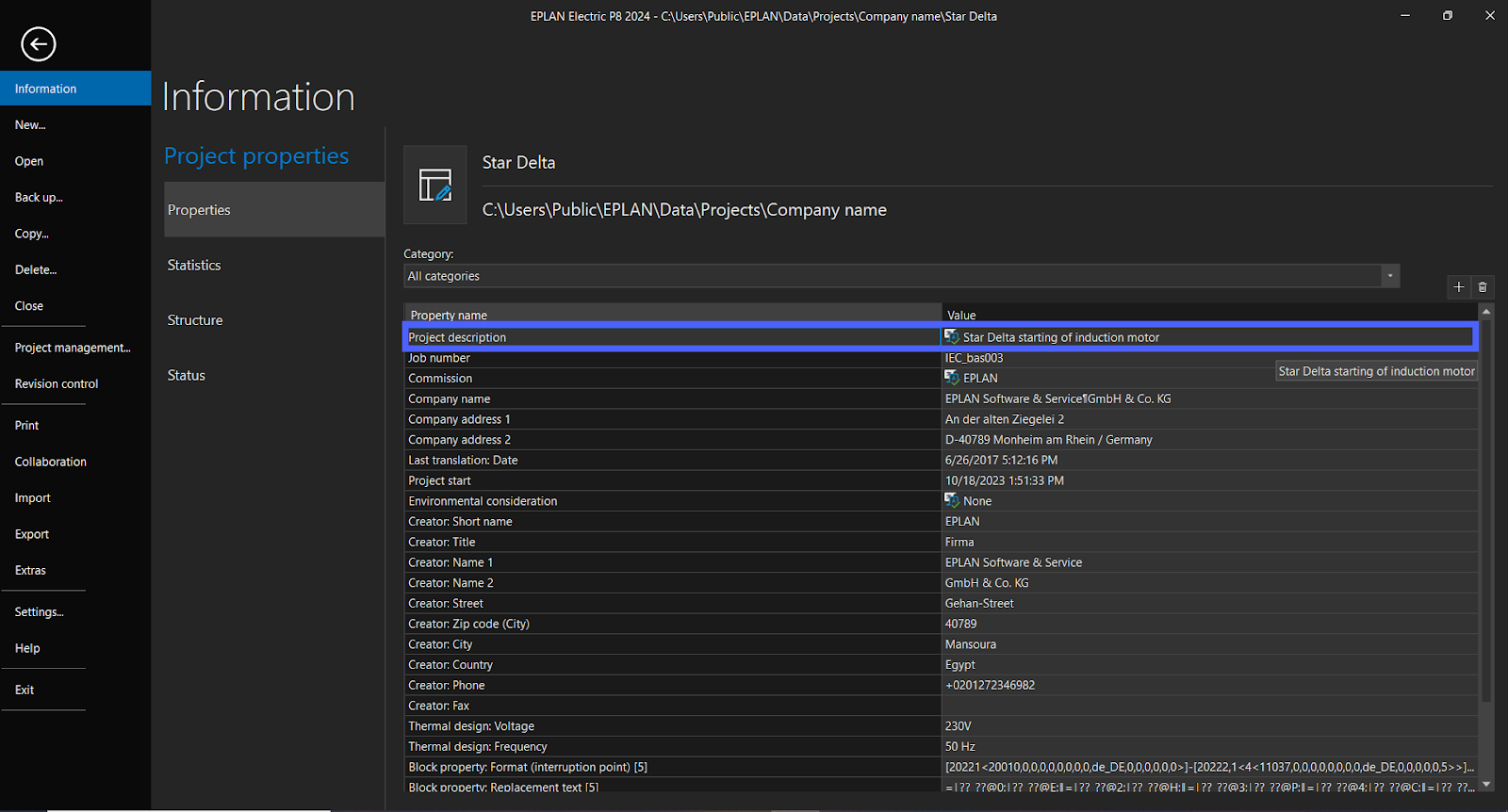
Note, if you don’t have a “project description” field in the “project properties.”
Click on “Add icon.”
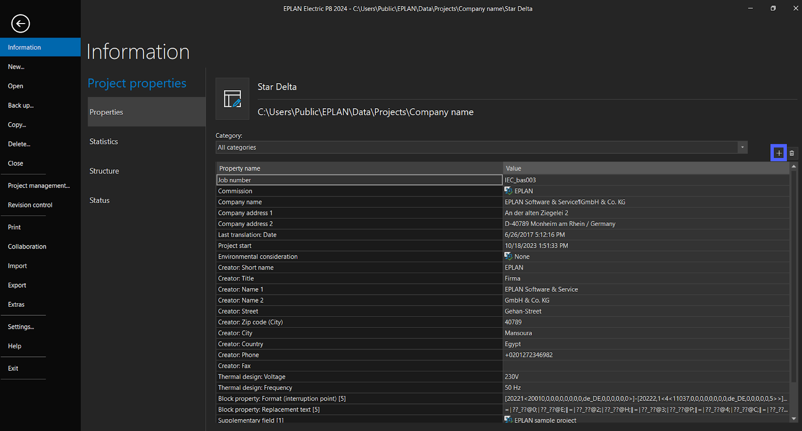
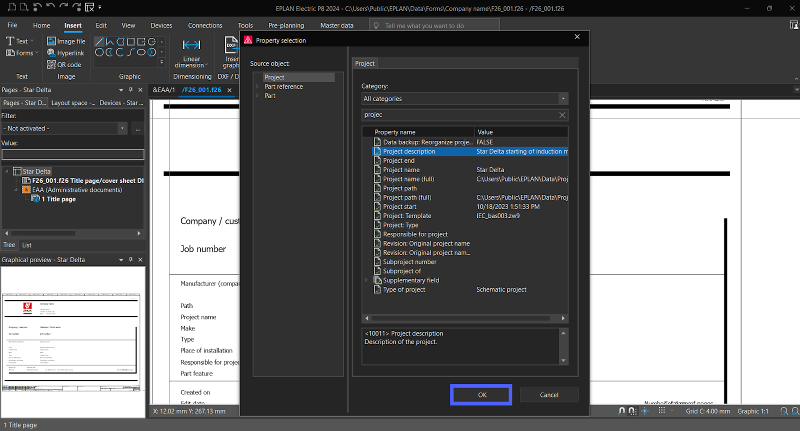
Figure 3.5– Getting Started with EPLAN | EPLAN Project properties
Search “Project description” and select the property then click “OK.”
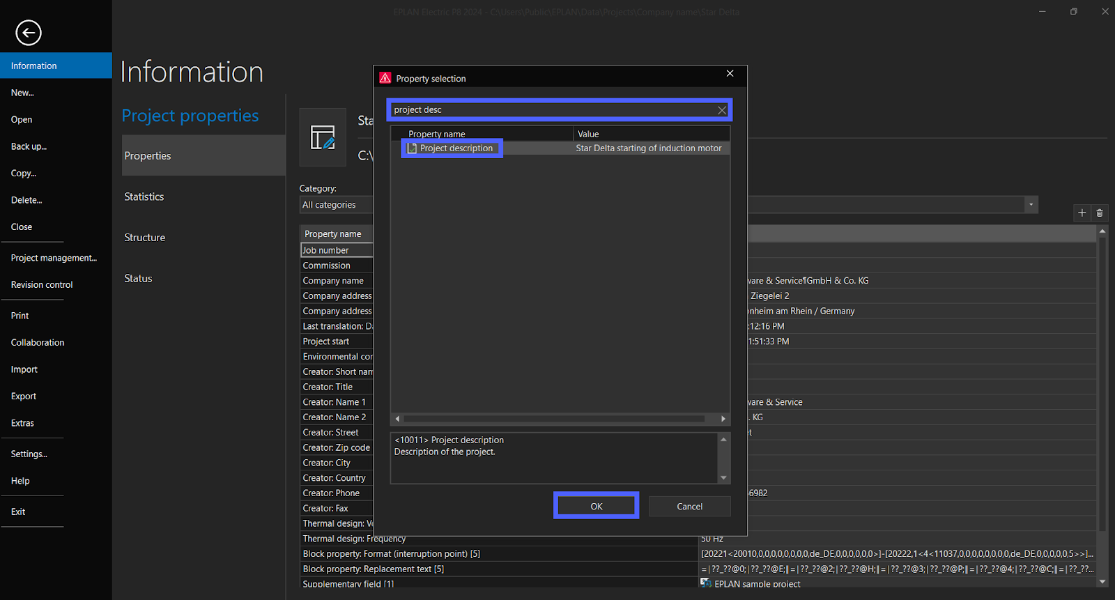
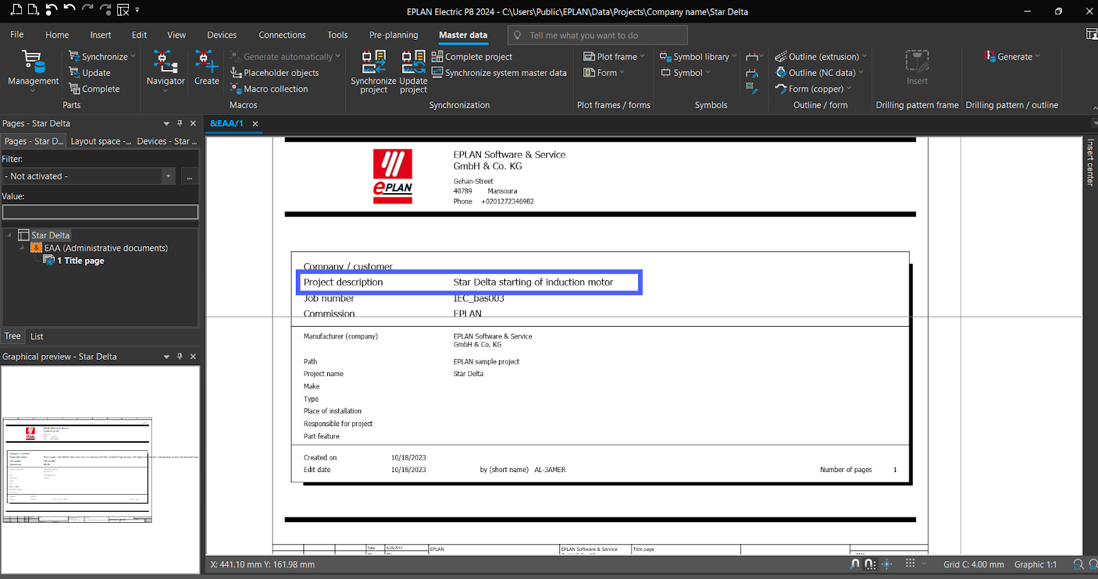
Now it’s added.
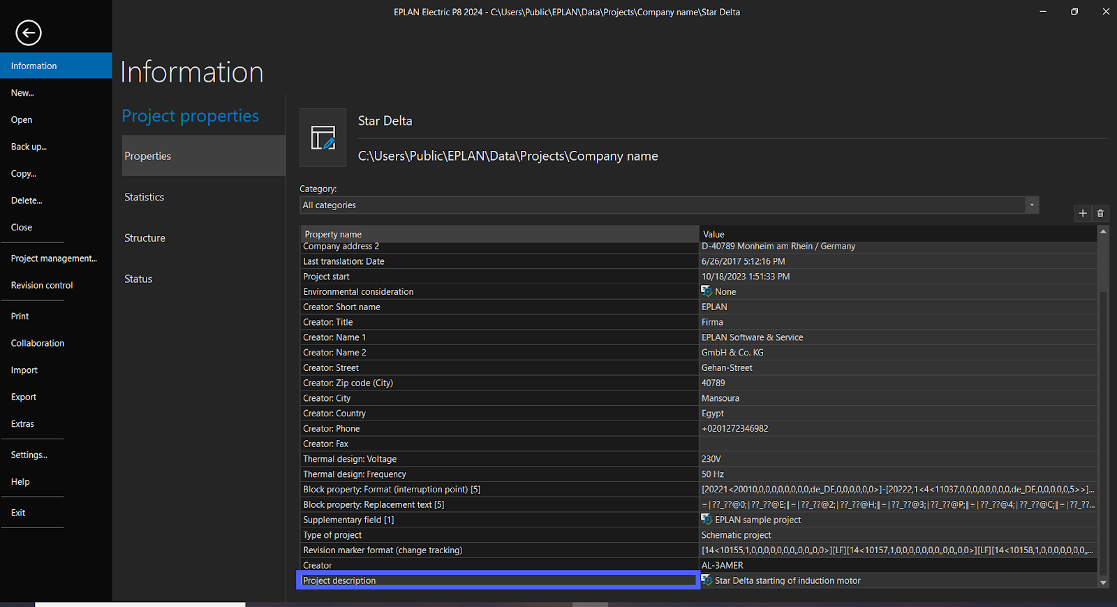
Note, you can do the same for other properties.
EPLAN – Add New Title Page
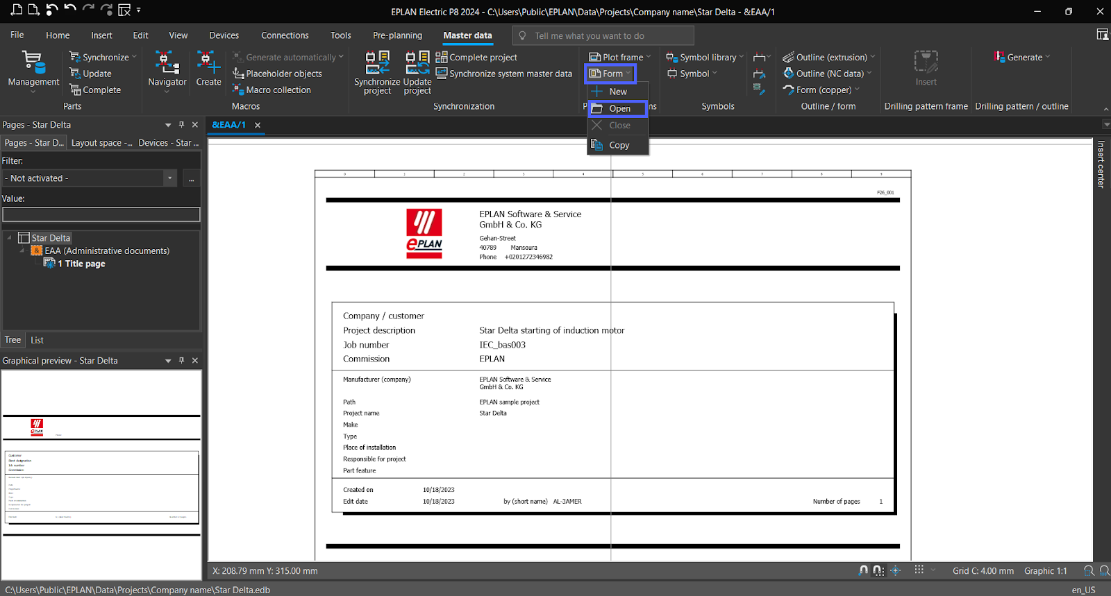
Select “Master data” from the menu bar.
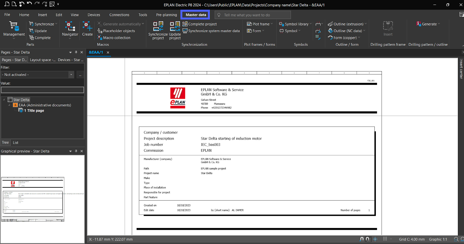
Click on “Form” then Select “Open.”
Select “title page/cover sheet.”
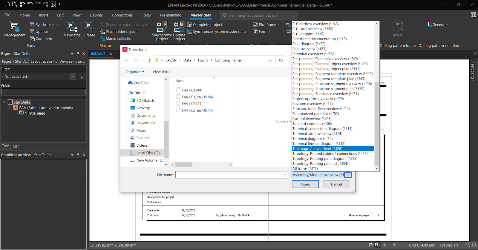
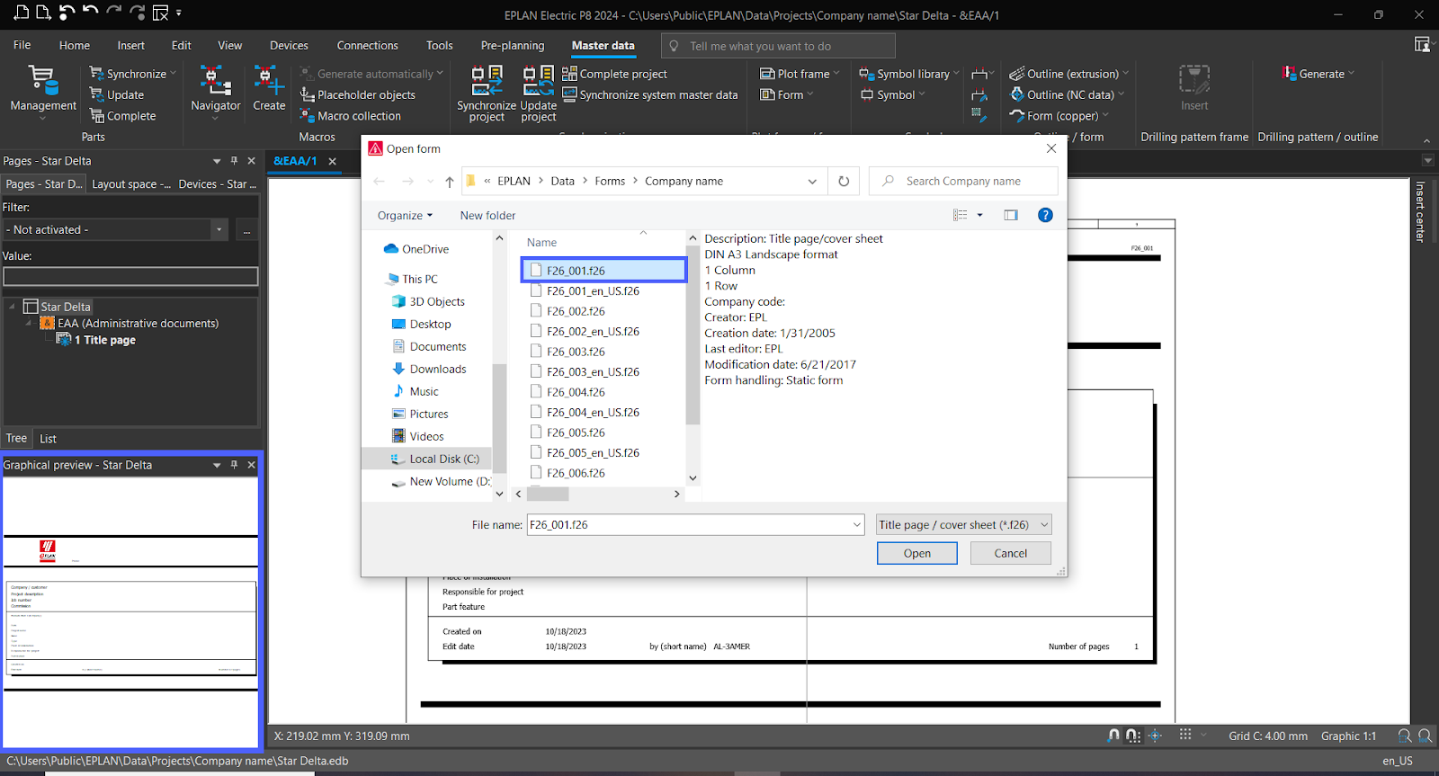
Select the suitable form then click “Open.”
You can see the form selected in the “Graphical preview.”
Now the Title page has been successfully added.
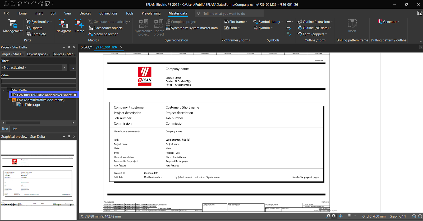
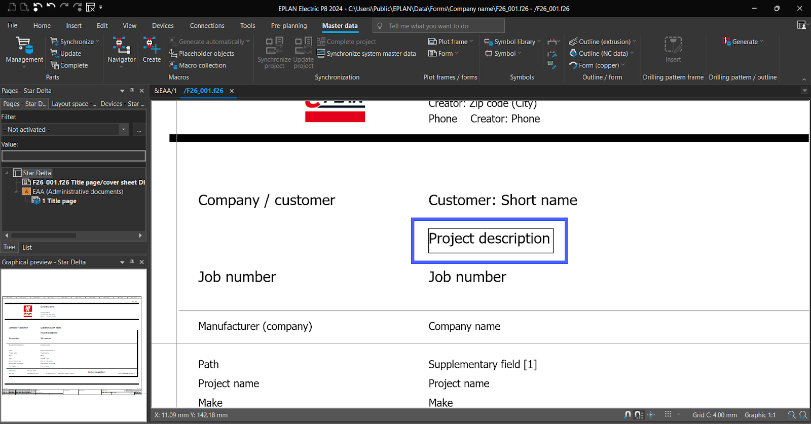
There are two type of text:
- Static text: This text remains constant and does not change.
- Special/Dynamic text: This text is variable.
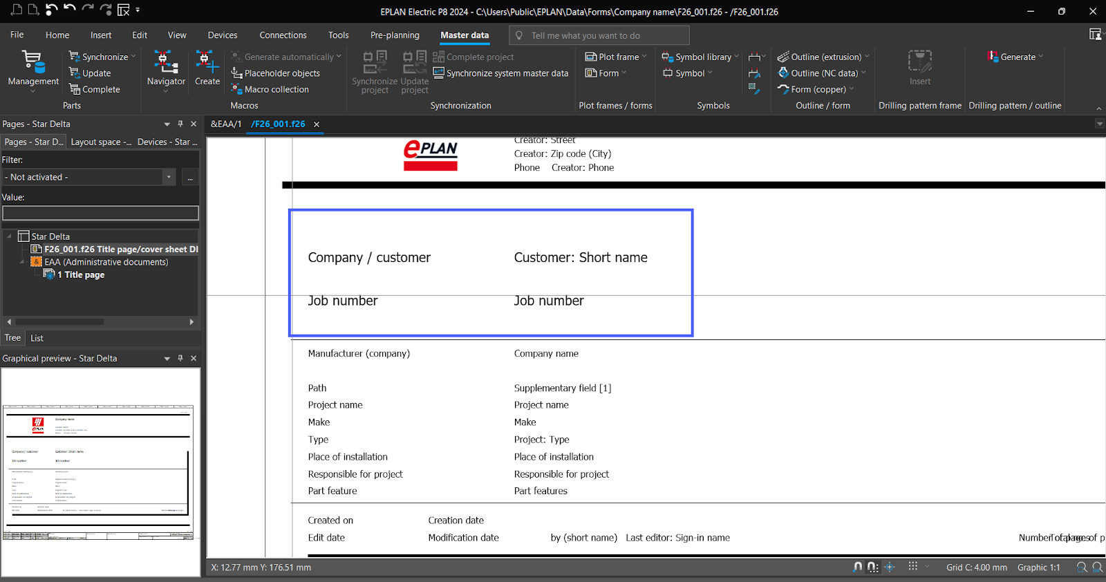
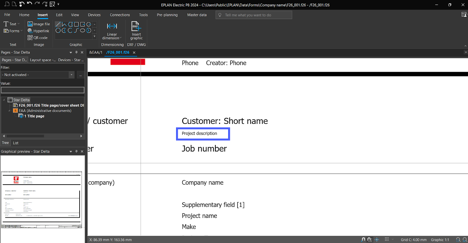
For example, the "project description" on the left is a static text, and the "Project description" on the right is a special text.

Now you can edit your own title page (delete, move, and add ) . Let's show only how to add a static text with special text.We deleted “Commission” and “project description”.
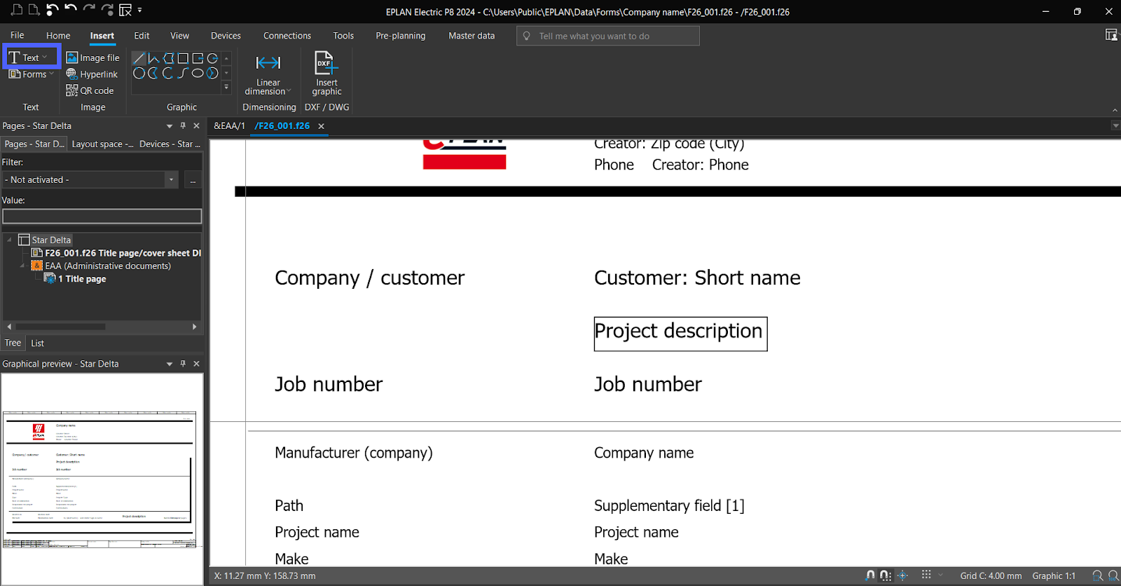
Let’s add “project description” to the title page.
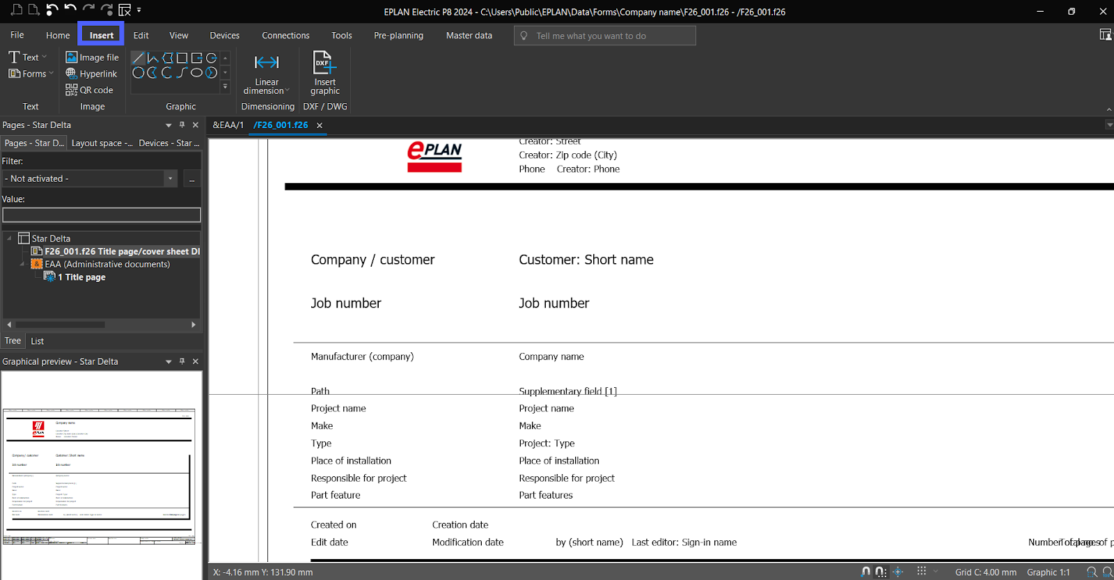
Click on “insert” in the menu bar.
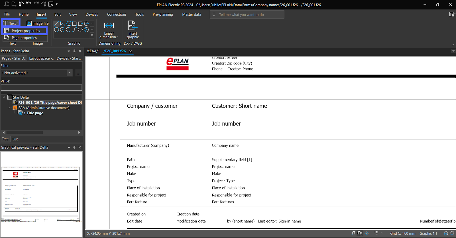
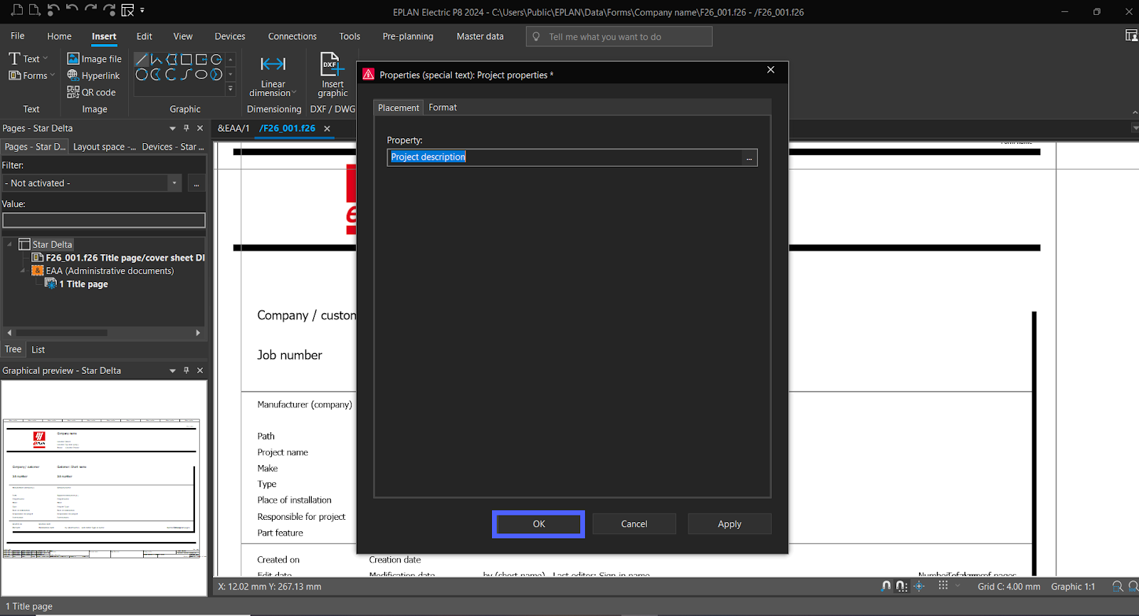
To add “Special Text” select “Text” then click on “Project properties.”
Select “Property.”
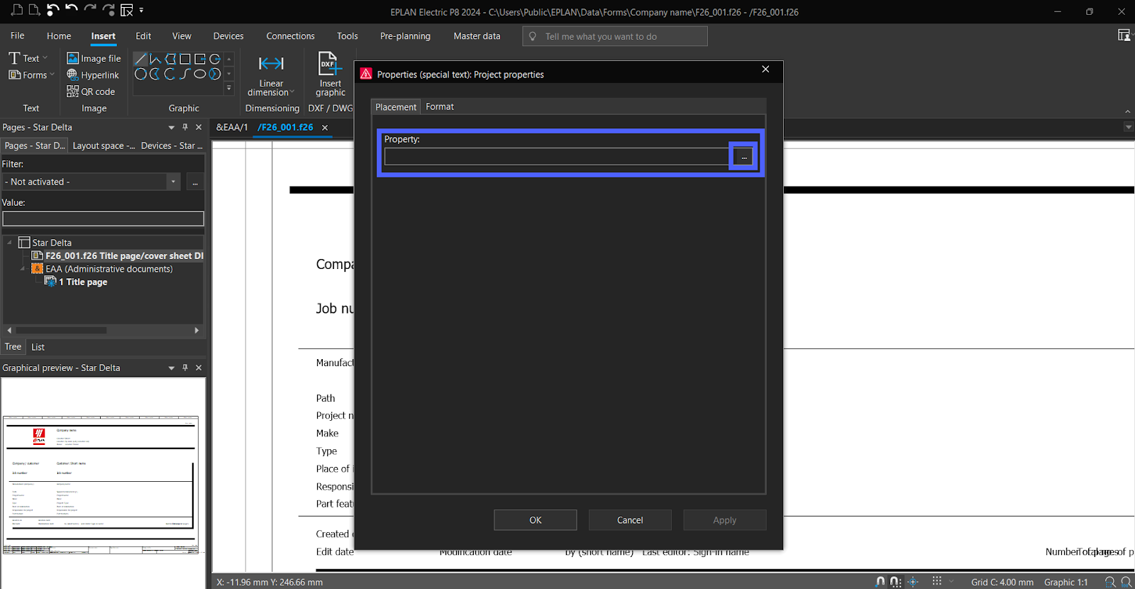
Select “Project description.” Then click “OK.”
Then Click “OK” and add it to the Title page.
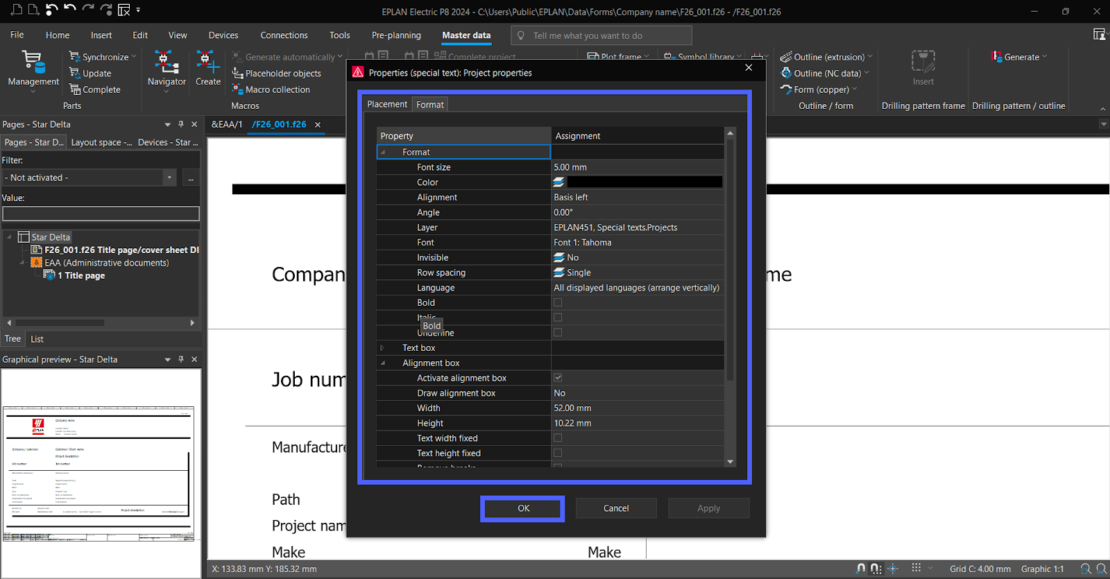
Double click on the text to modify its format. Then click “OK.”
Now let’s add Static text. Click on “Text.”
Enter the text and set its format, then click “OK.”

Add static text now to the Title page.

Now, you can modify your own title page. You can add images too by selecting “Insert” next “Image file.”
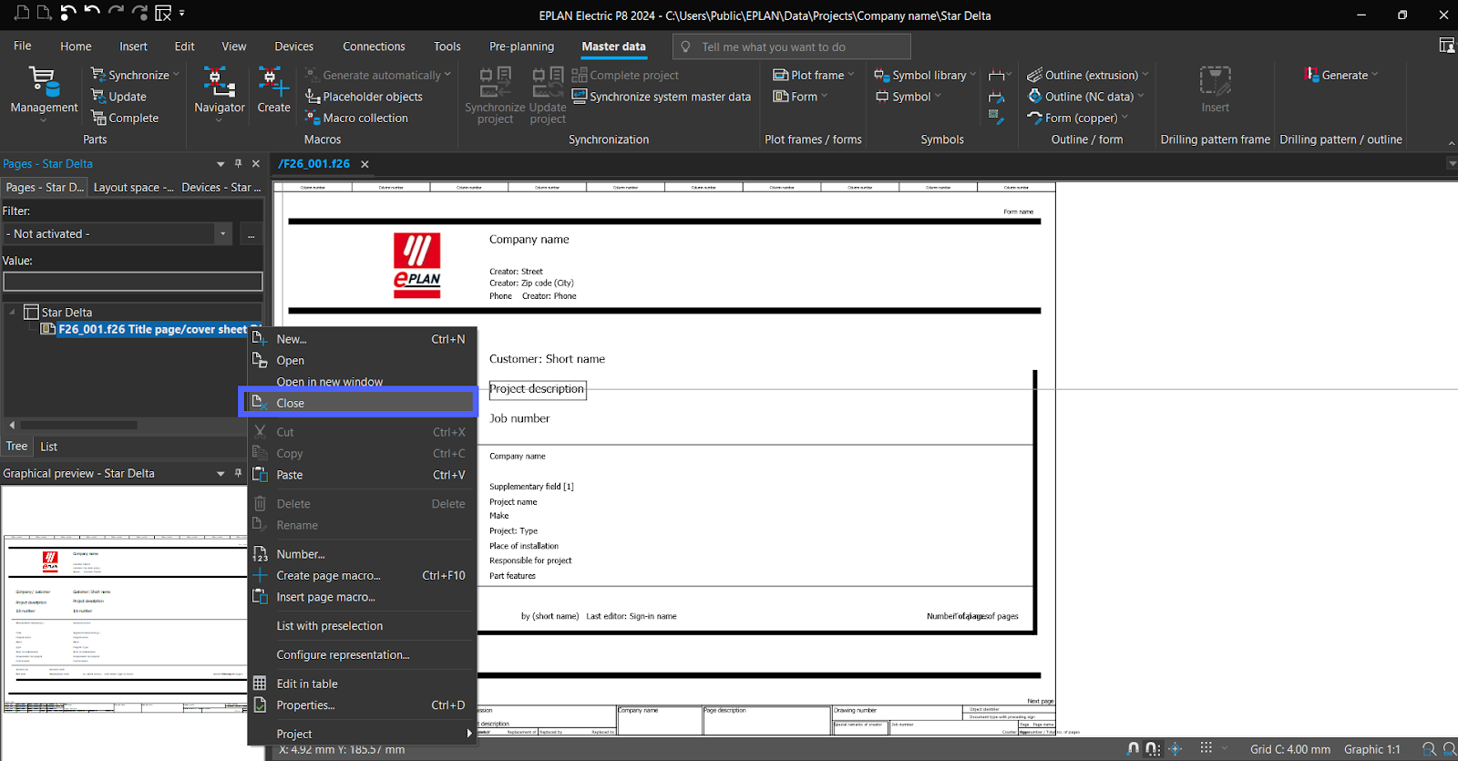
Now let’s add it to the project, delete the old “Title page.” Then Right click on “Title page” and click “Close.”
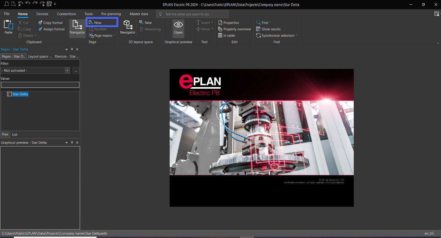
From “Home” in the menu bar select “NEW page icon,” or from “page navigator” right Click and select “New. Or click on “CTRL + N. “
In “Page type” select “Title page / cover sheet” and in “Form name” select your own form of new Title page then click “OK.”
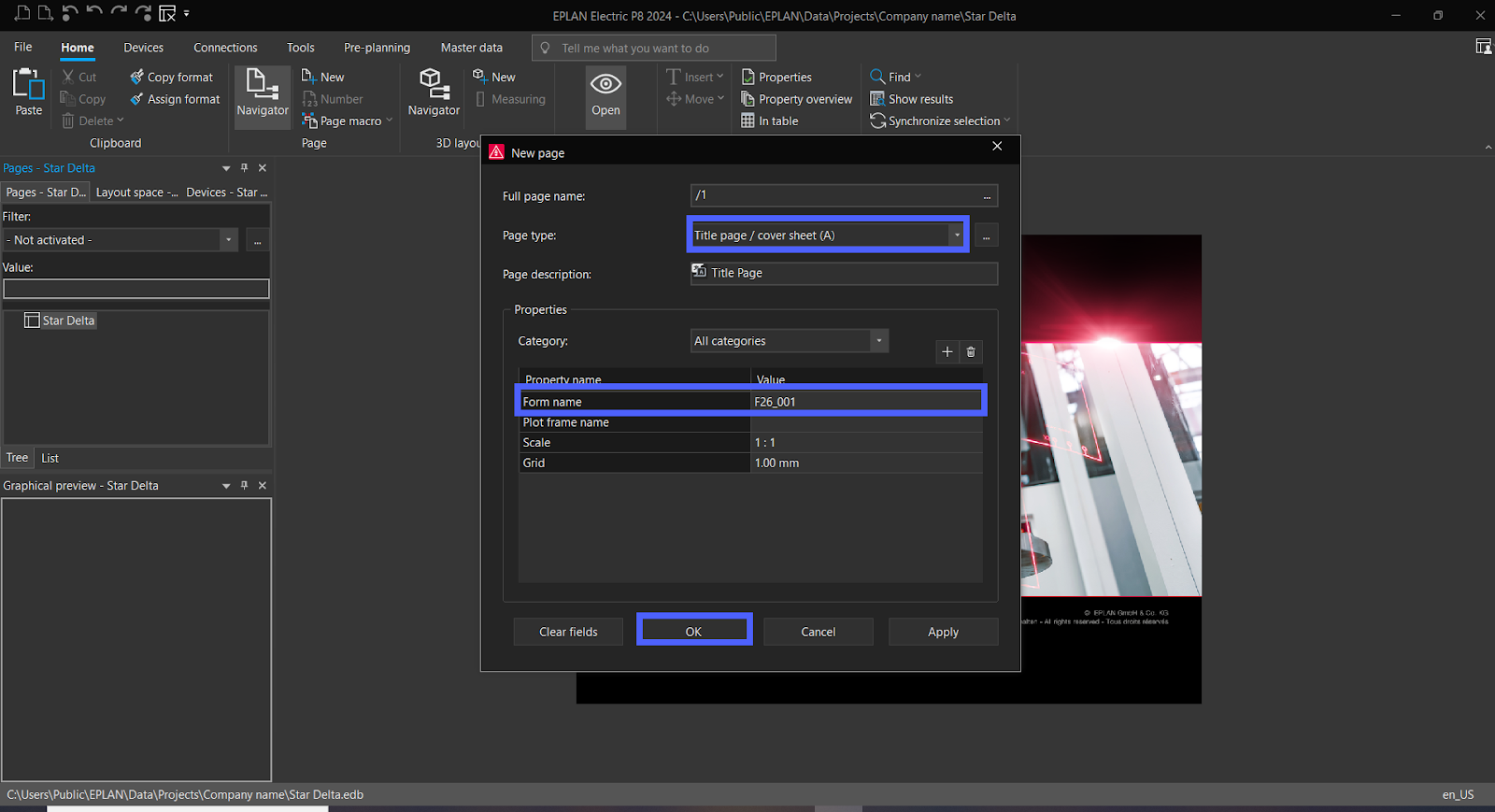
Now all is done, and you can modify properties as we mentioned before.

EPLAN – Power Circuit Diagram
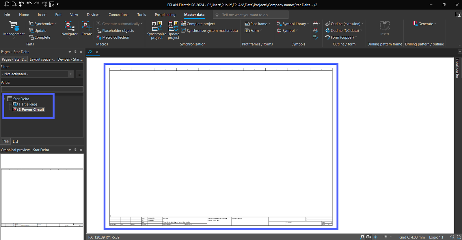
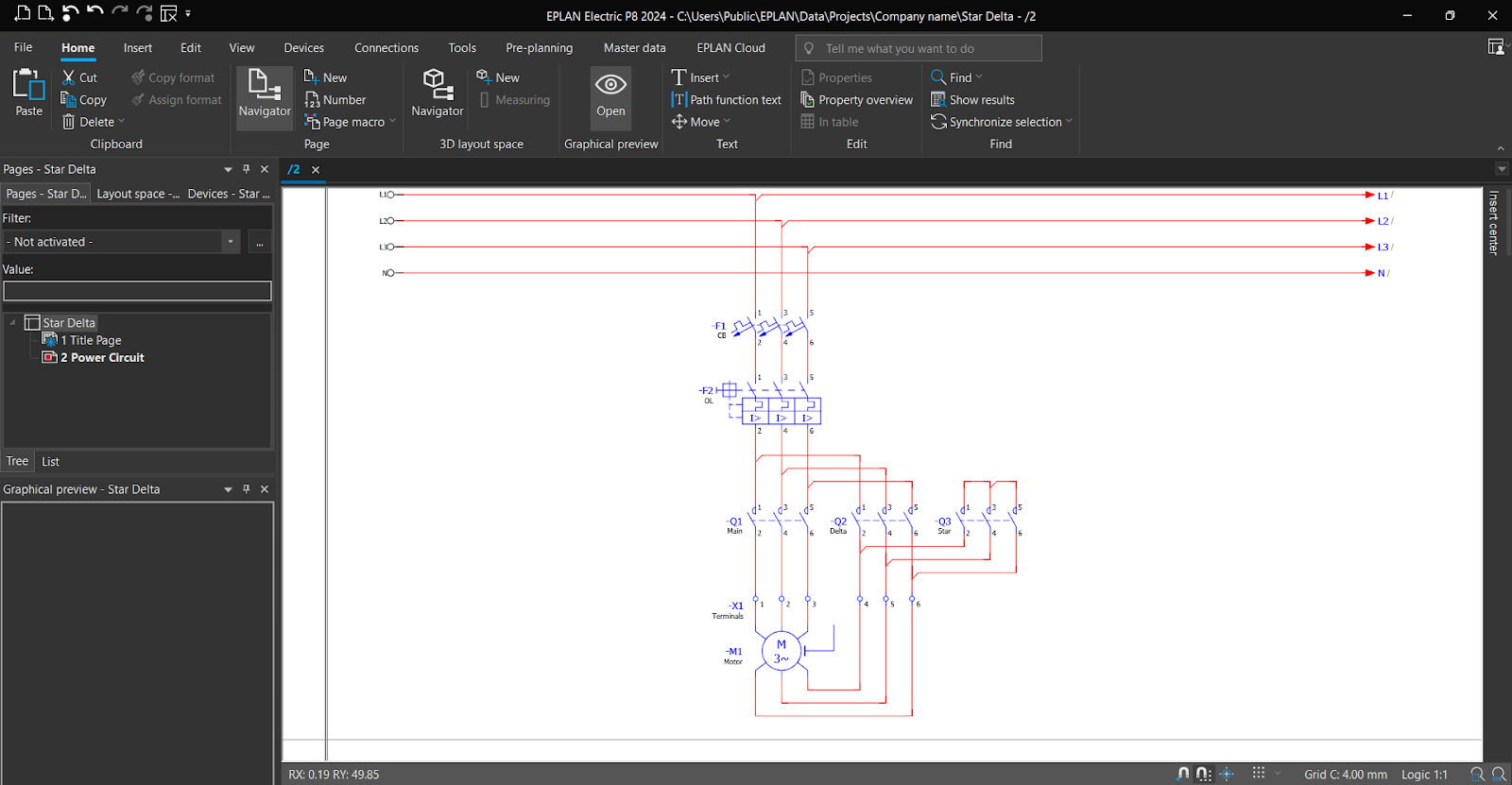
We will design a power and control circuit for the Star Delta starting method, specifically for an induction motor. Let’s start with the Power Circuit Diagram. Add a new page.
In “Page Type,” select “Schematic multi-line,” and in “Plot frame name,” select any suitable “plot frame” then click “Ok.” | Note: you can create your plot frame following the steps we used for the "Title page."

Now, the Power Circuit Page has been successfully added.
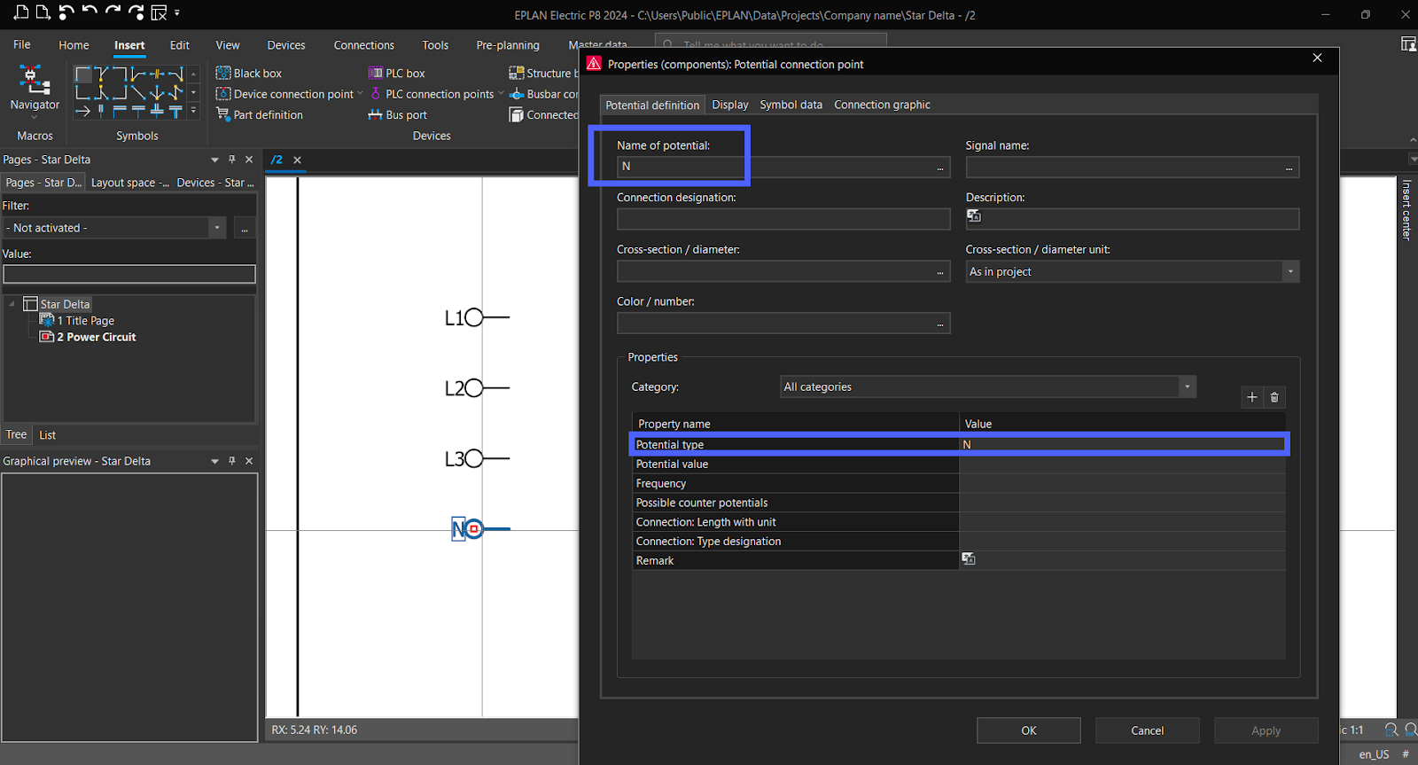
From “Insert,” select “Potential Connection Point” from “Connection.” And add it to “Plot frame.” | Note: use “CTRL” For Rotating.
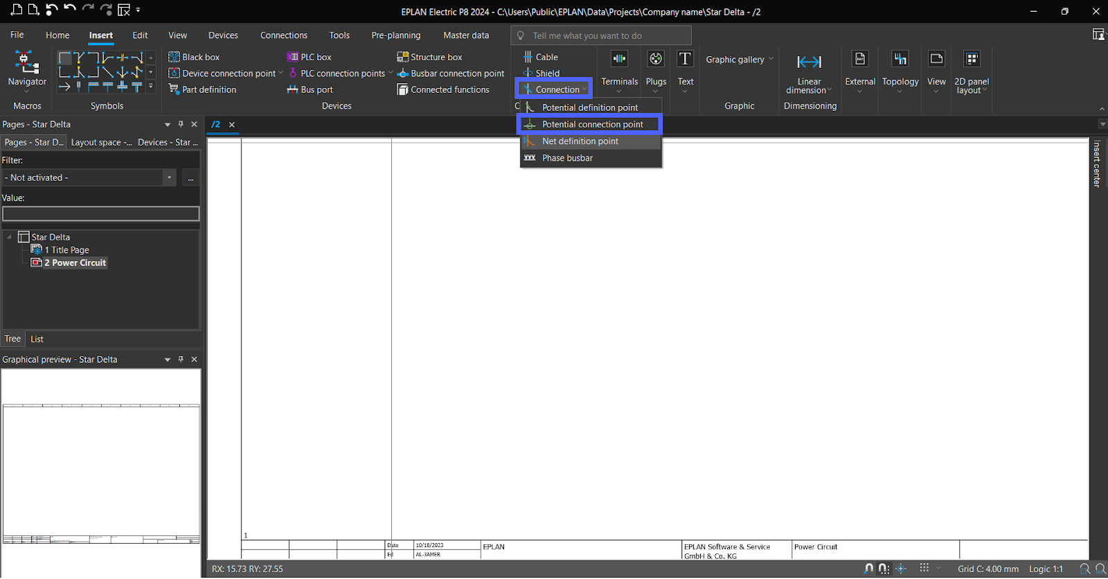
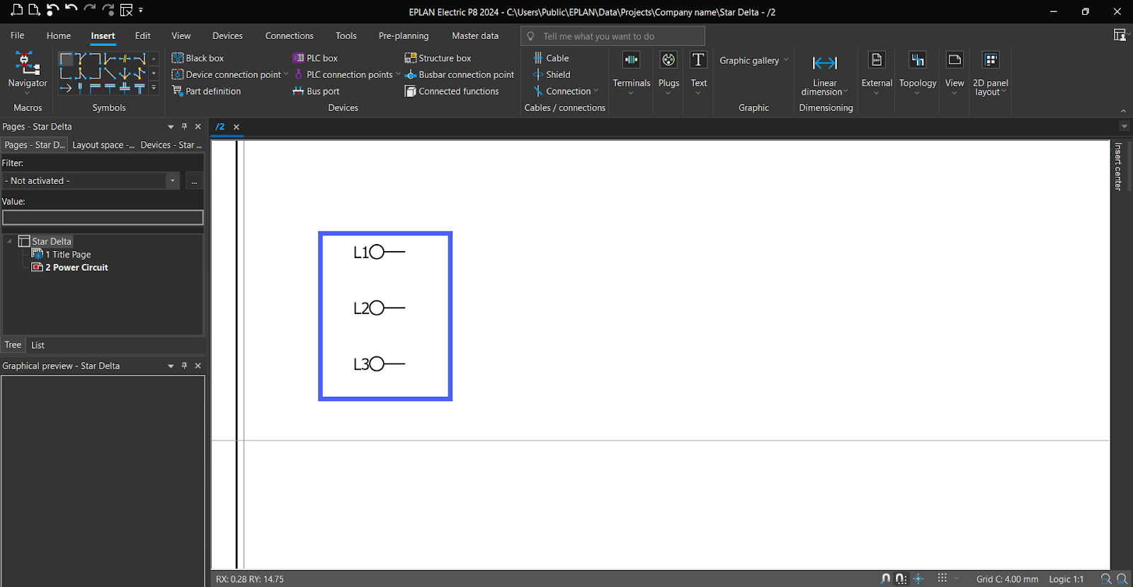
Name it as “L1” and choose “L” as the “Potential type,” then click “OK.”

In the same way, add “L2” and “L3”.
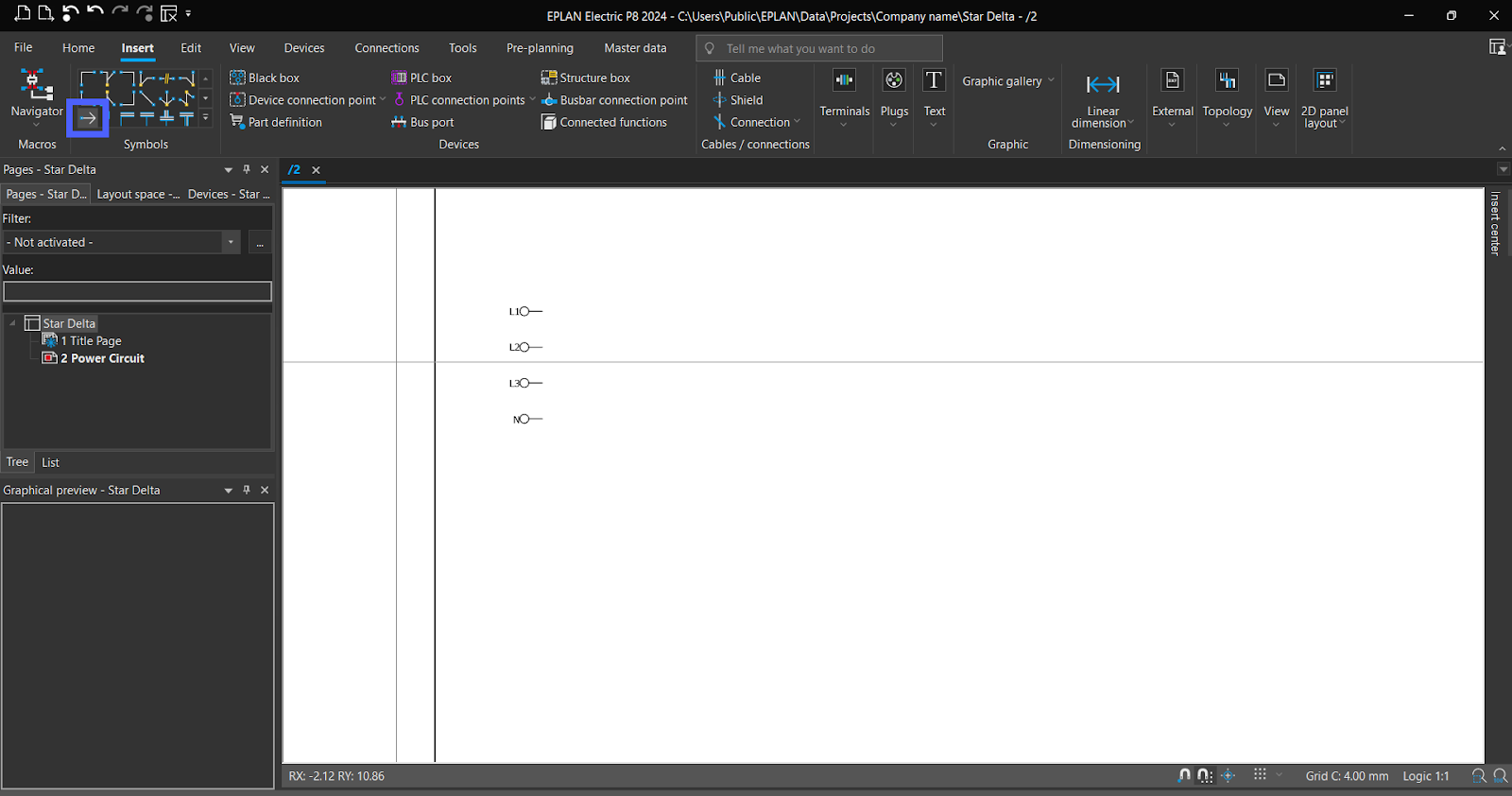
Now add “N”
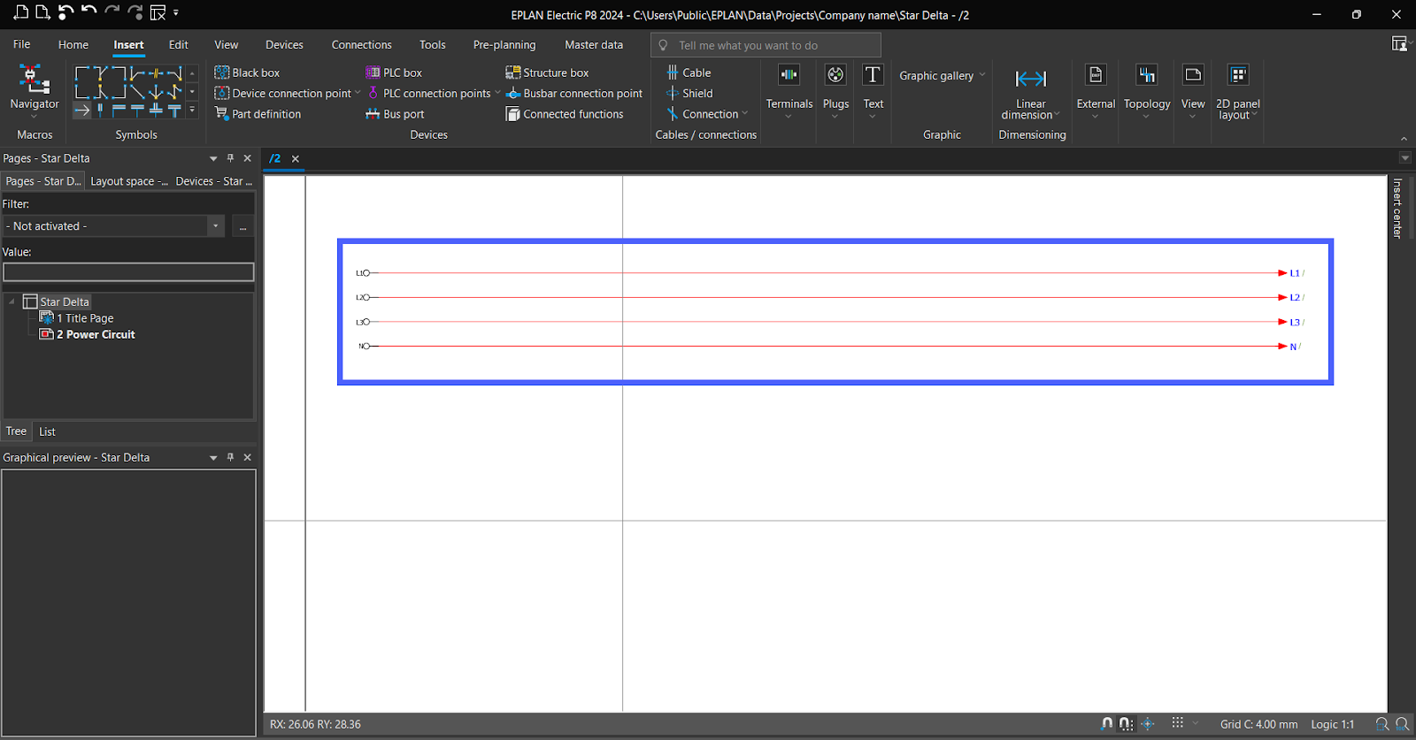
Now, From “Insert,” Get the “Interruption Point” and connect with 3 lines and neutral.
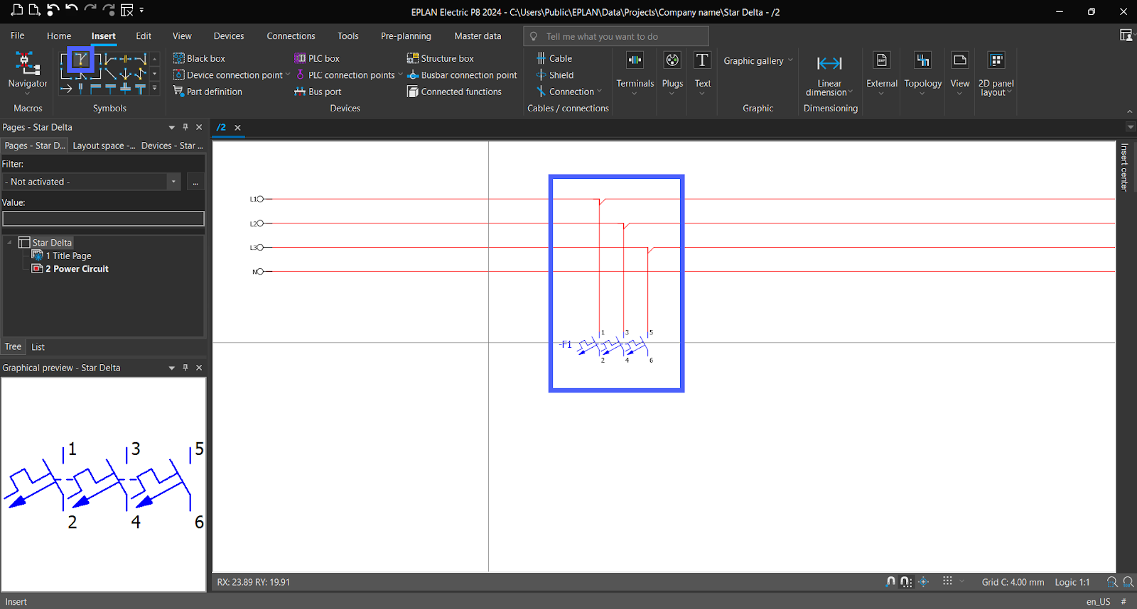
To add a "Circuit Breaker," access the "Symbols" section from the "Insert Center."
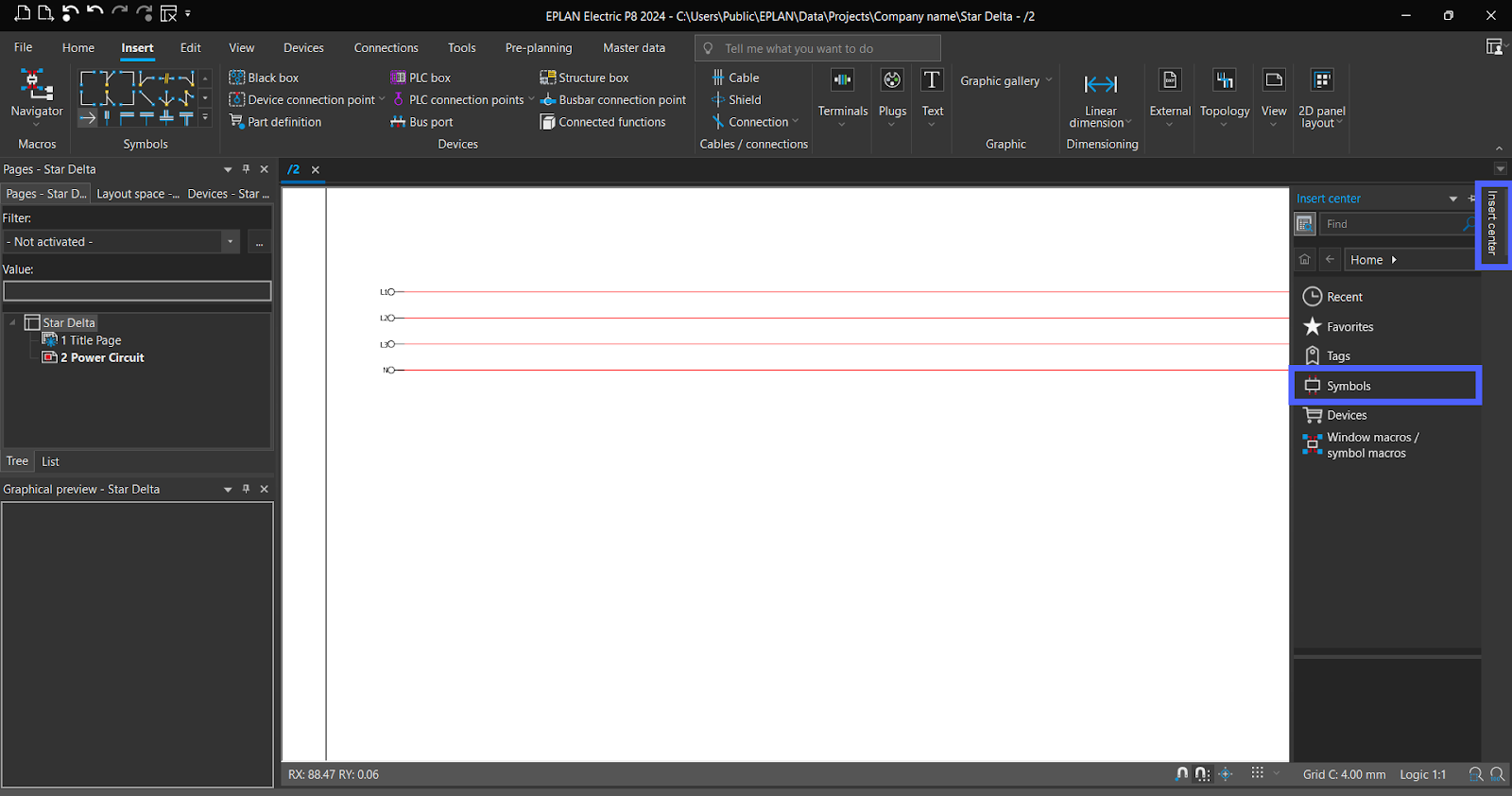
Choose "IEC_symbol," then go to "Electrical engineering," followed by "Protection device," and finally select "Circuit breaker."
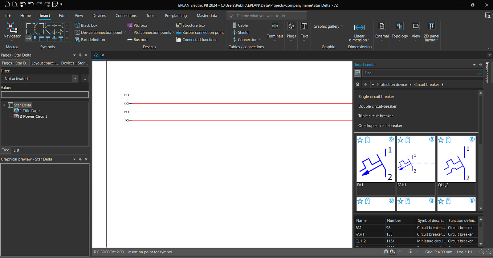
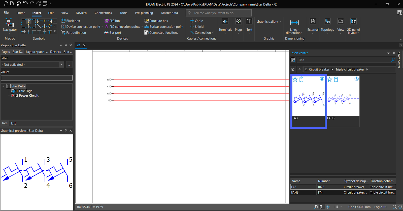
Choose “Triple circuit breaker.”

Drag symbol to schematic.
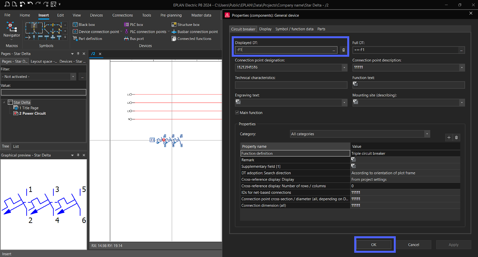
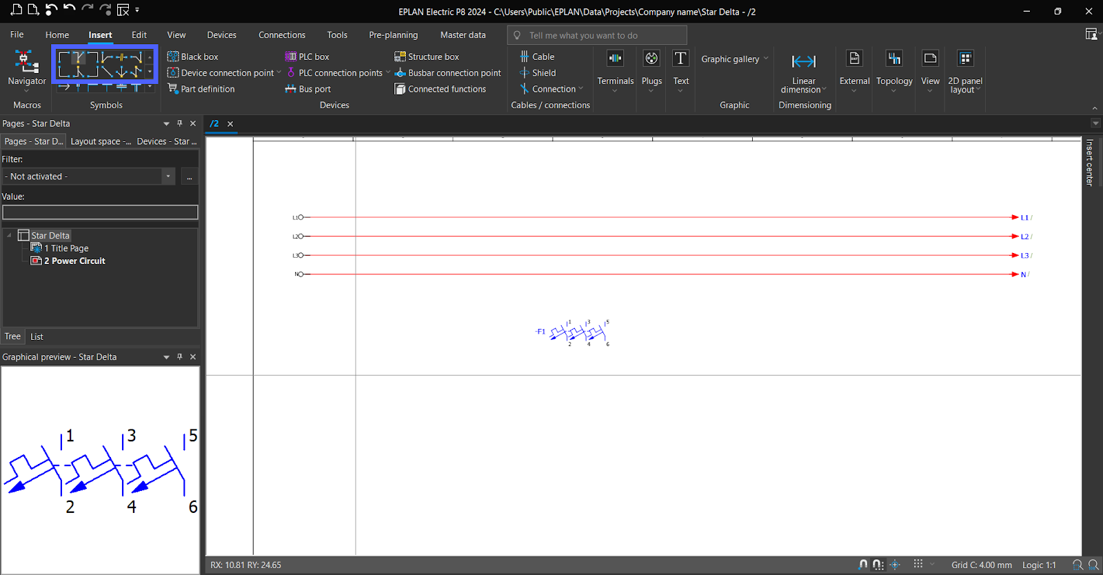
Set a name, then “OK.”
To establish connections, From "Insert," use "Lines" and "Nodes."
We will use “T-node down”.
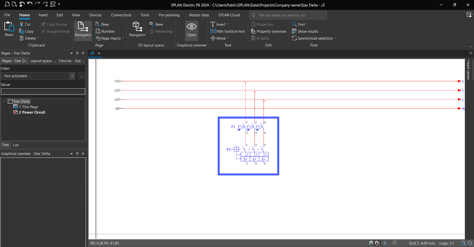
Let’s add “Overload relay.”
Choose "IEC_symbol," from “Symbols” then go to "Electrical engineering," followed by "Protection device," and finally select "Motor overload switch."
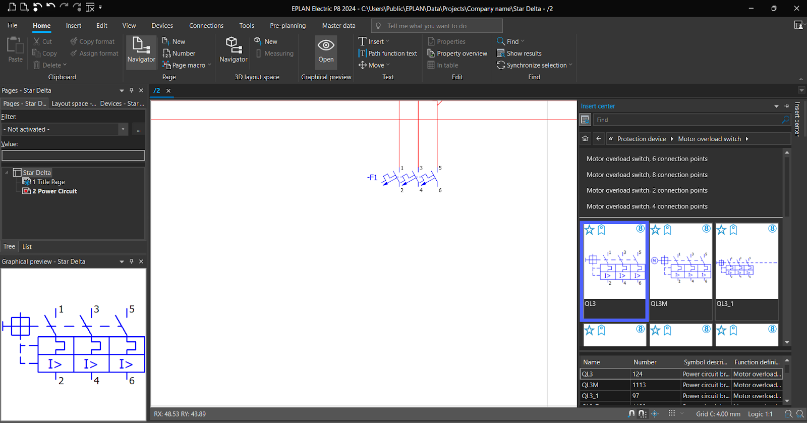
Drag the symbol to the schematic under the CB, and It will be automatically connected with the CB.
Note, add your suitable protection Devices.
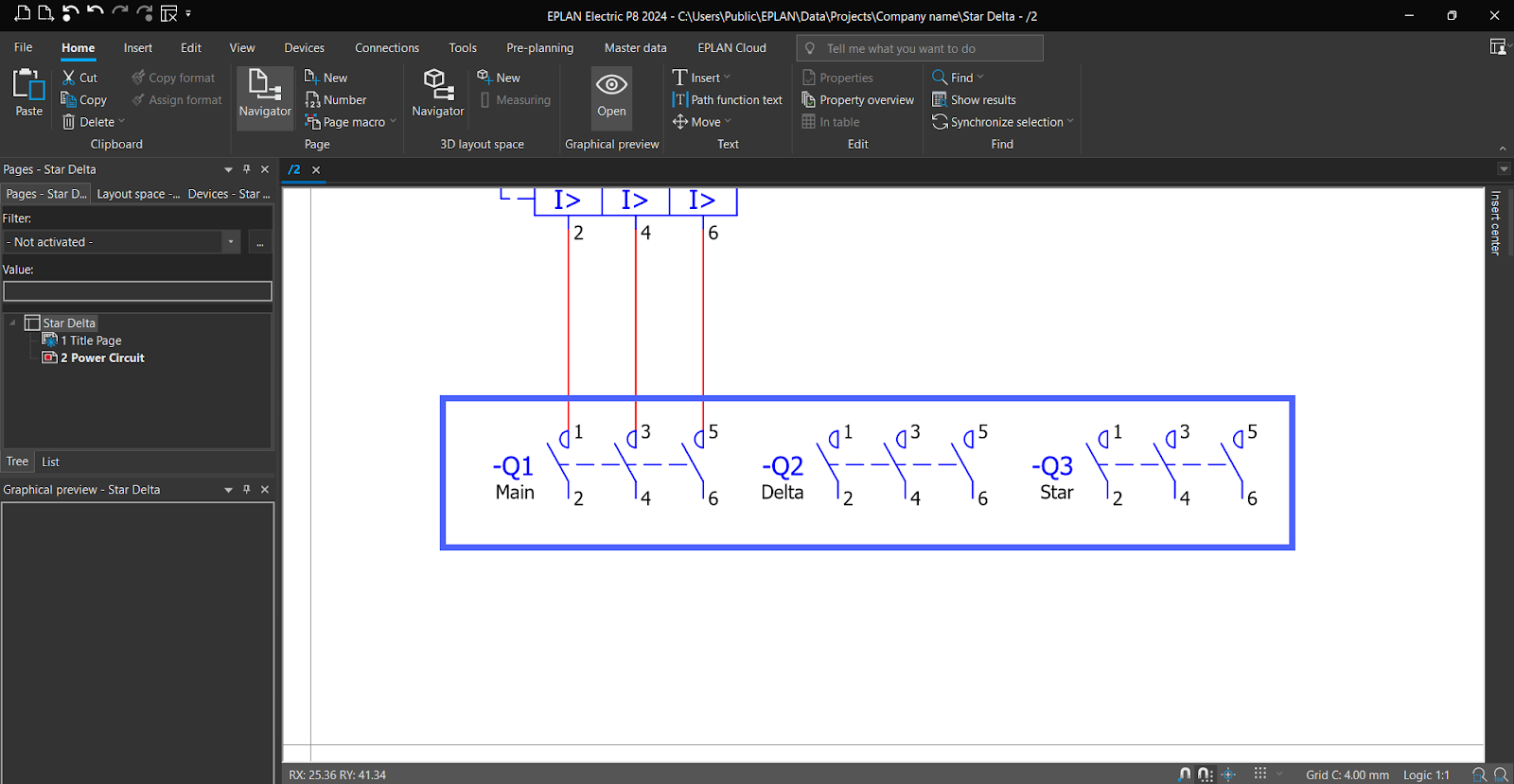
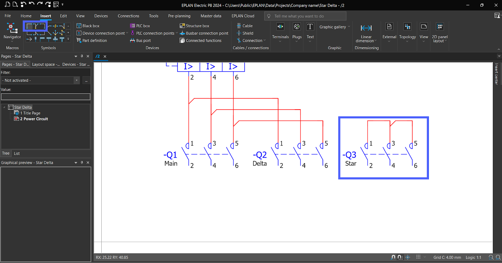
As the same, add Three main NO Contacts of Contactors.
Select "IEC_symbol" from the "Symbols", navigate to "Electrical engineering," proceed to "Coils, contacts, and protective circuits," and then select "NO contact" and specifically and finally select "NO contact, 3 connection points".
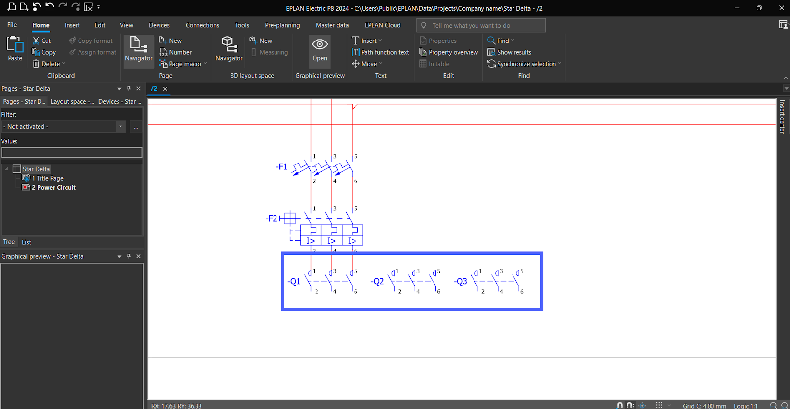
To add functionality text, double-click "Contacts," set the desired functionality text, and click "OK."
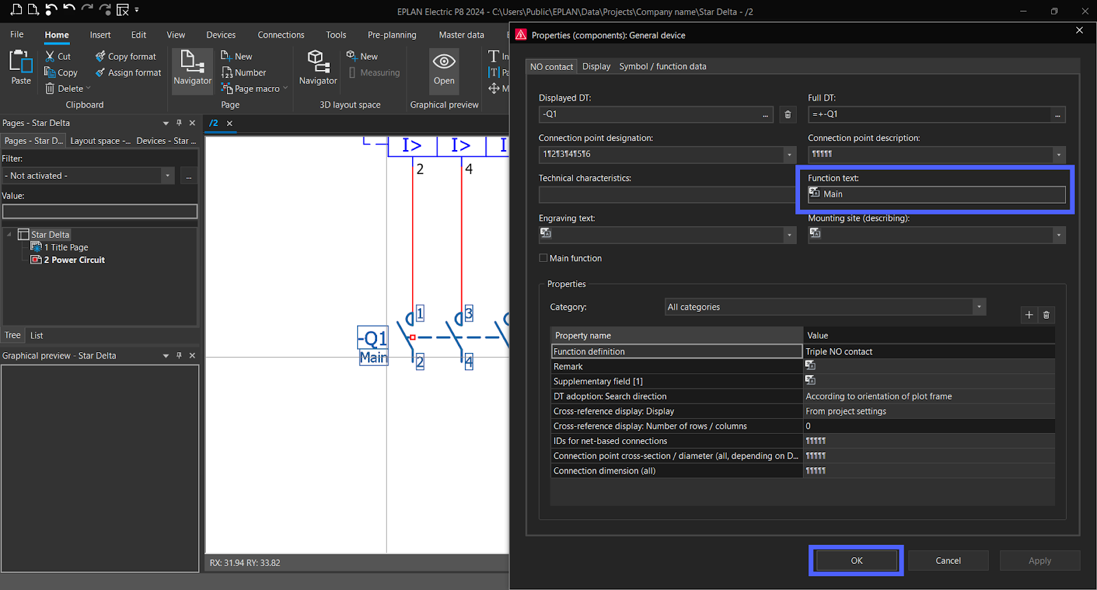
Assign the "function text" to all three contacts.
Place three "T-node right" symbols in the three respective lines to establish connections.
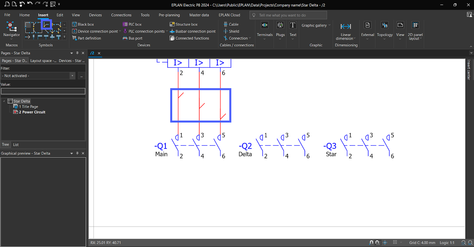
Connect the "Angle down" symbol to the "T-node right" symbol to establish the desired connections.
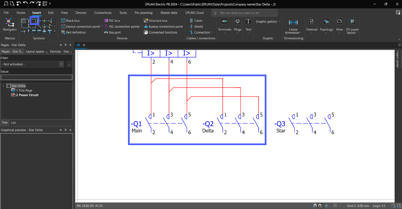
Use “Angle Right,” ”Angle left,” and ”T-node down” symbols To establish connections for the “Start contacts.”
Now let’s add “Terminals” to connect with Motor.
From "IEC_symbol" in the "Symbols” add “Terminal with 2 connection point.”
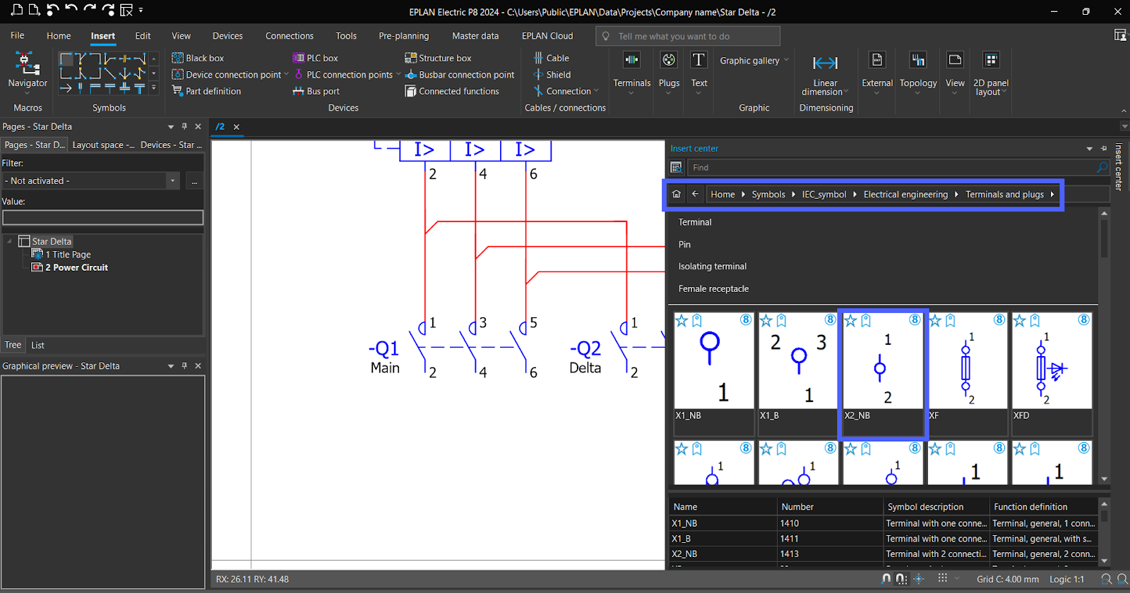
Add 6 Terminals.

Now add the Motor.

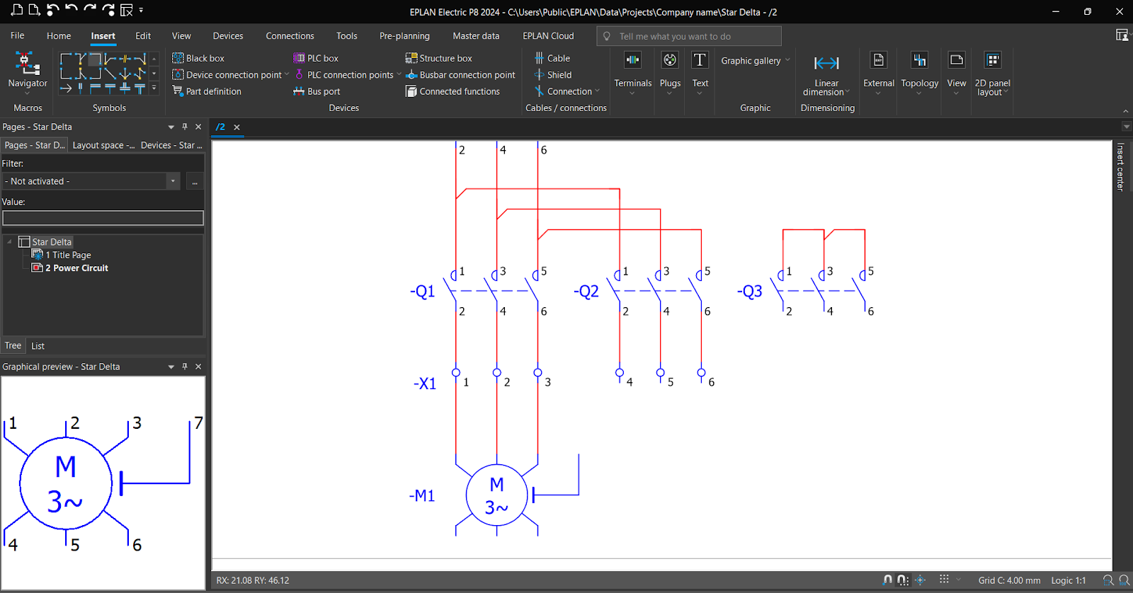
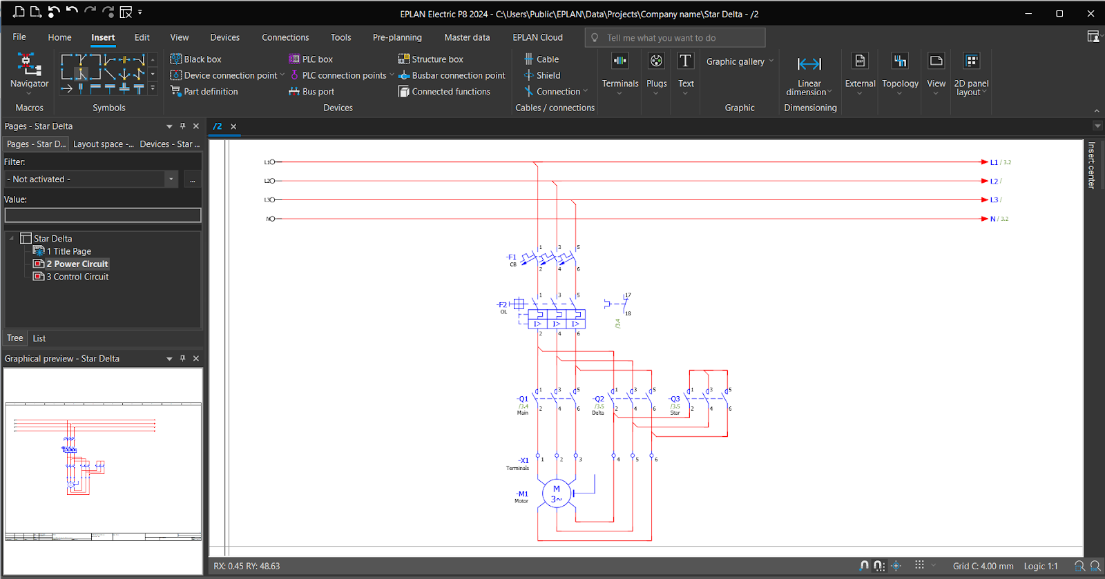
Let’s complete the connections.
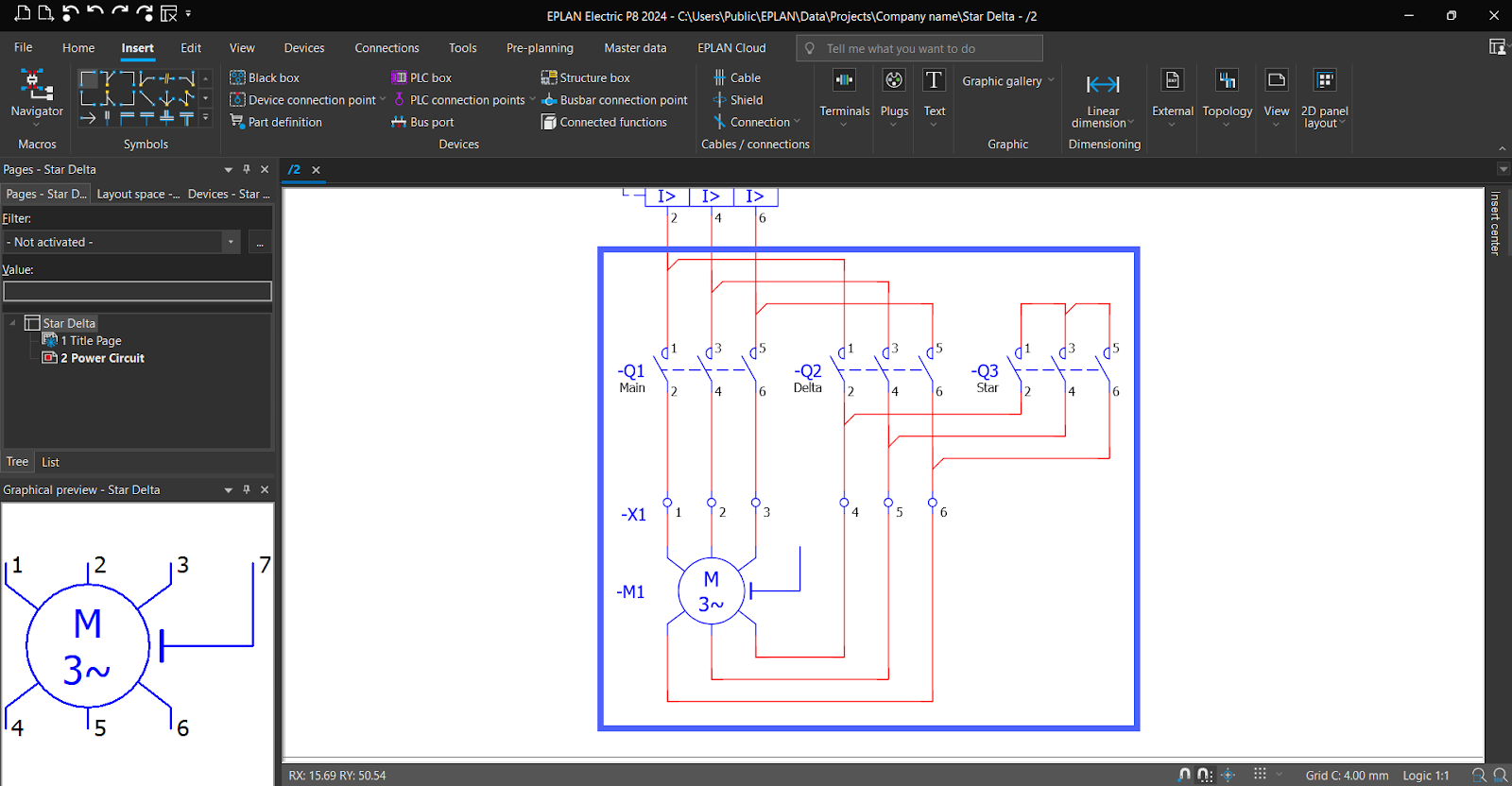
Add “Function Text” for all elements and we are done!
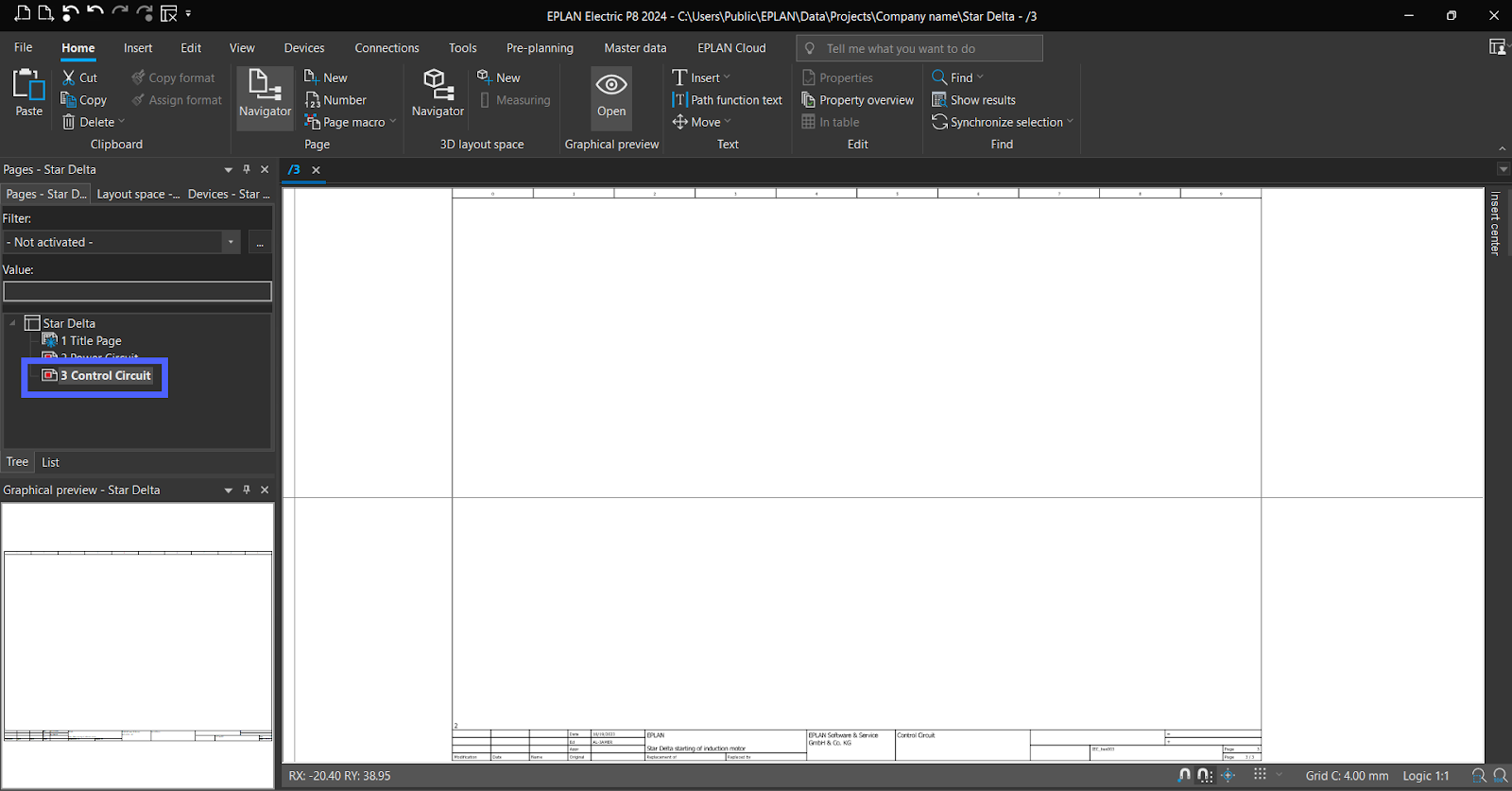
EPLAN – Control Circuit Diagram
Add a New Page.
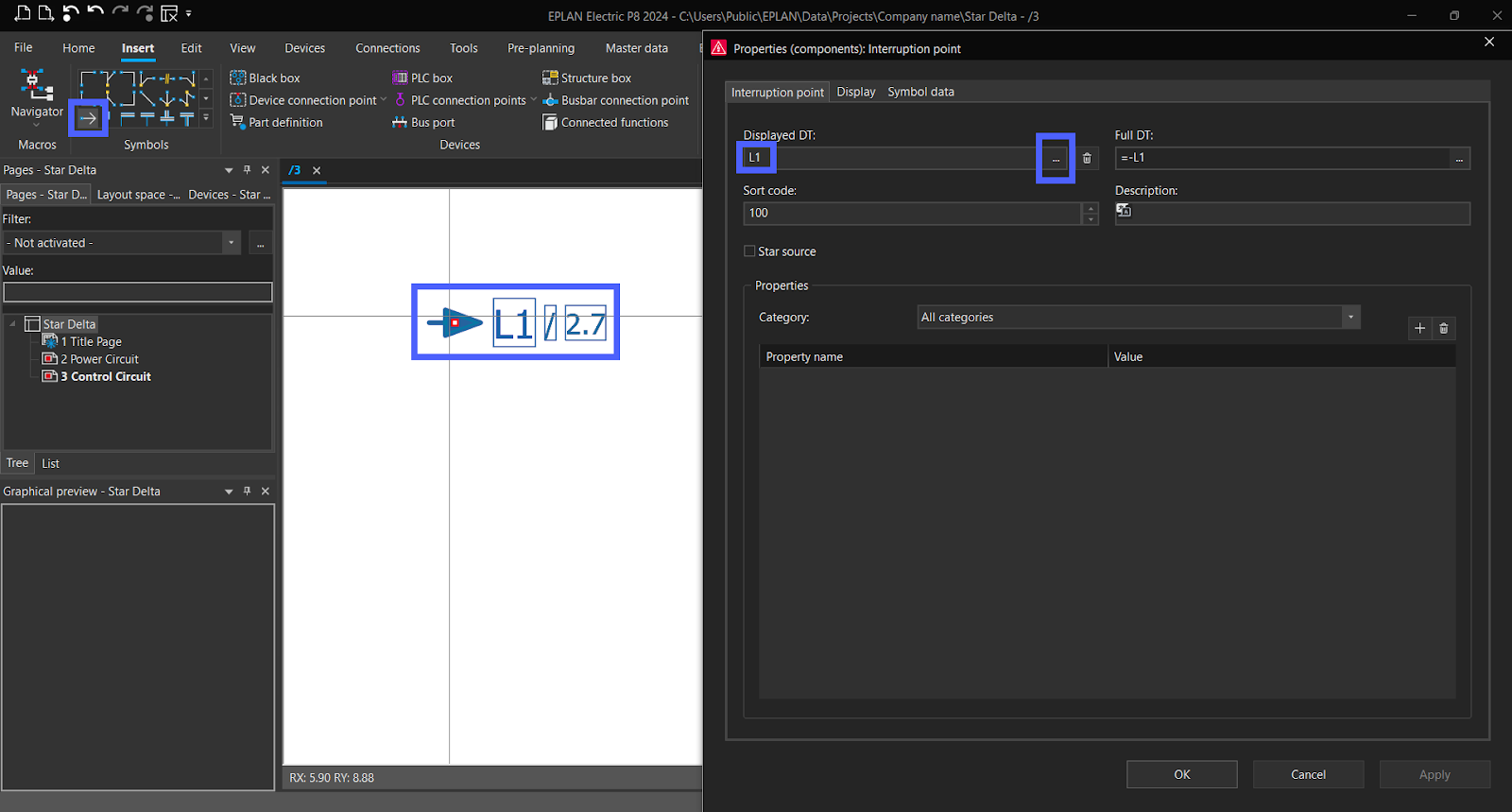
To add L and N to the control circuit, employ the "Interruption point" symbol and configure it as "L1," then click "OK."
Same for N.

Note, the number "2.7" indicates that the "Interruption point" is connected to N, corresponding to page 2, row 7 in the schematic.
Note, it would be beneficial to create a separate page for Power Supply Wiring, enhancing the organization and clarity of the schematic.
Add two "Interruption point" symbols to the schematic. And move “N” to down.

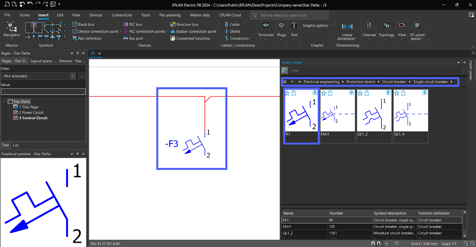
Include a "single phase circuit breaker" symbol in the schematic and connect it to "L1."
Let’s add NC contact from “Overload.”
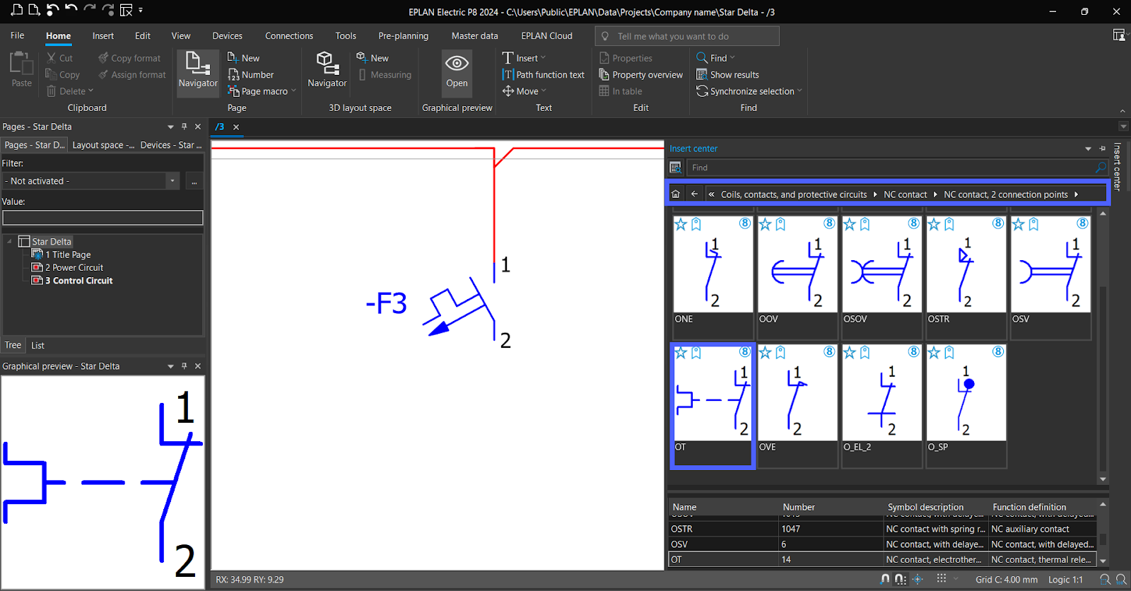
Drag to the schematic. Select “-F2,” the name of “overload in power circuit page,” then “OK.”


Navigate to the symbols section to find the "Stop Pushbutton" symbol.
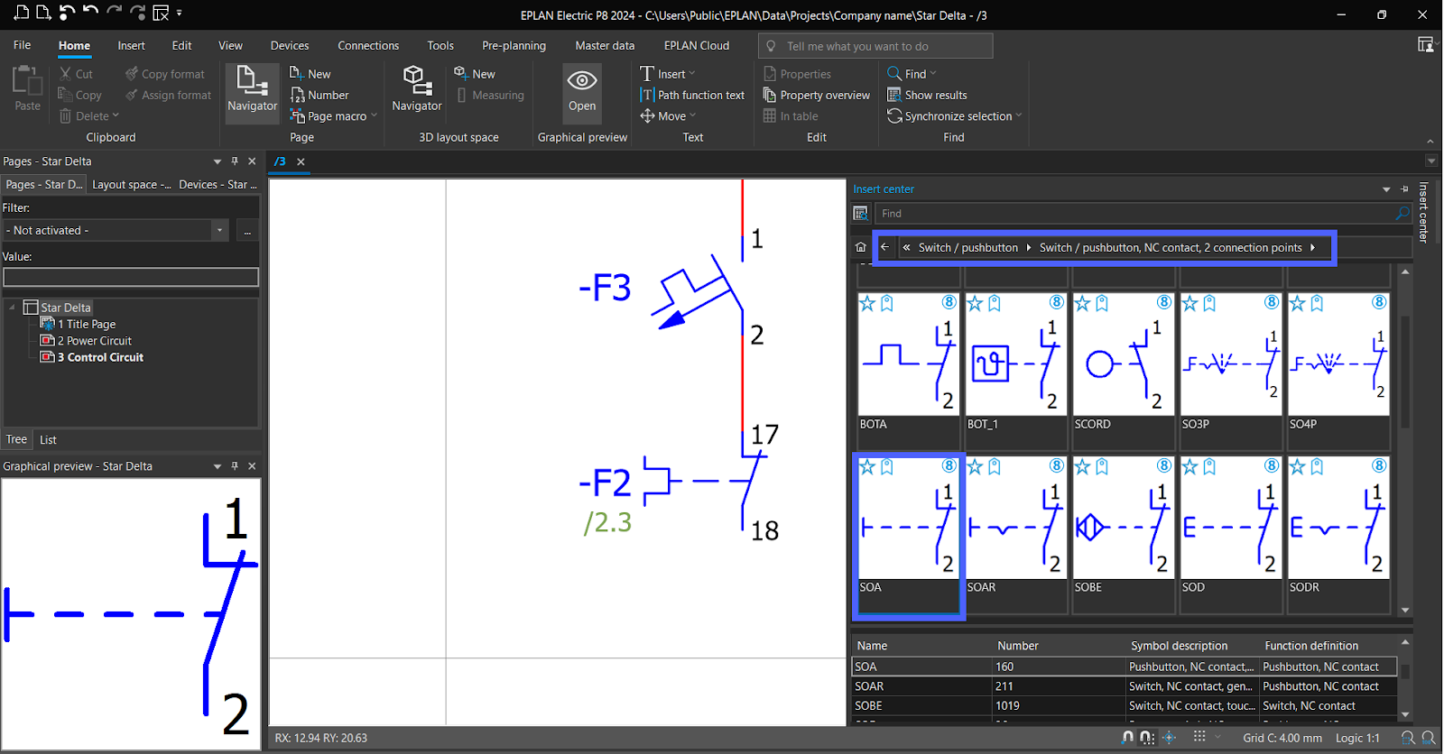
Drag to schematic.
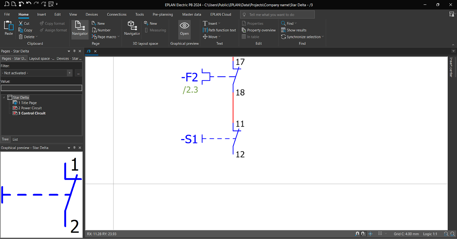
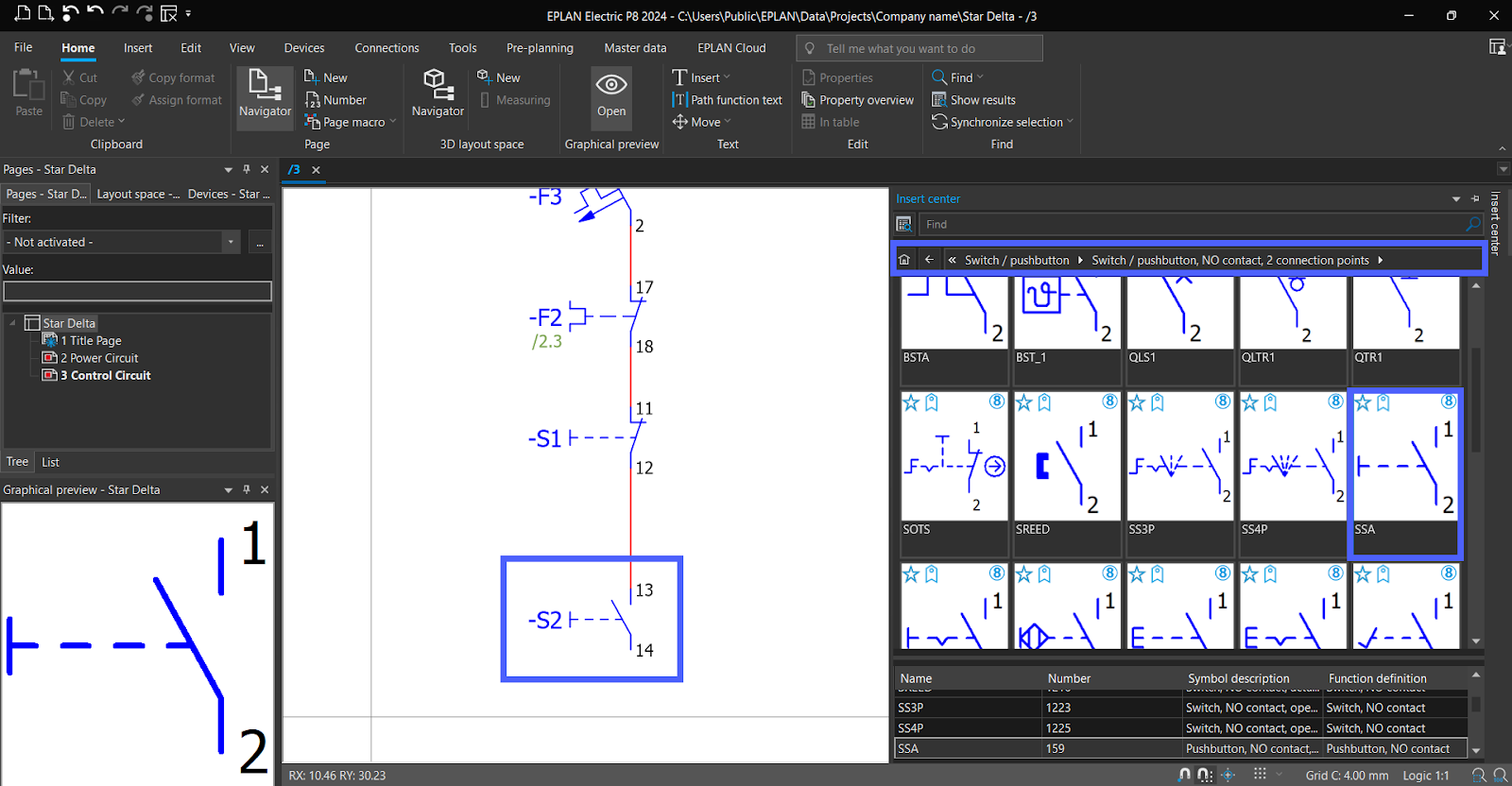
Now, Navigate to the symbols section to find the "Start Pushbutton" symbol. Then Drag to schematic.
Now, Navigate to the symbols section to find the "Coils" symbol for contactor and Timer.
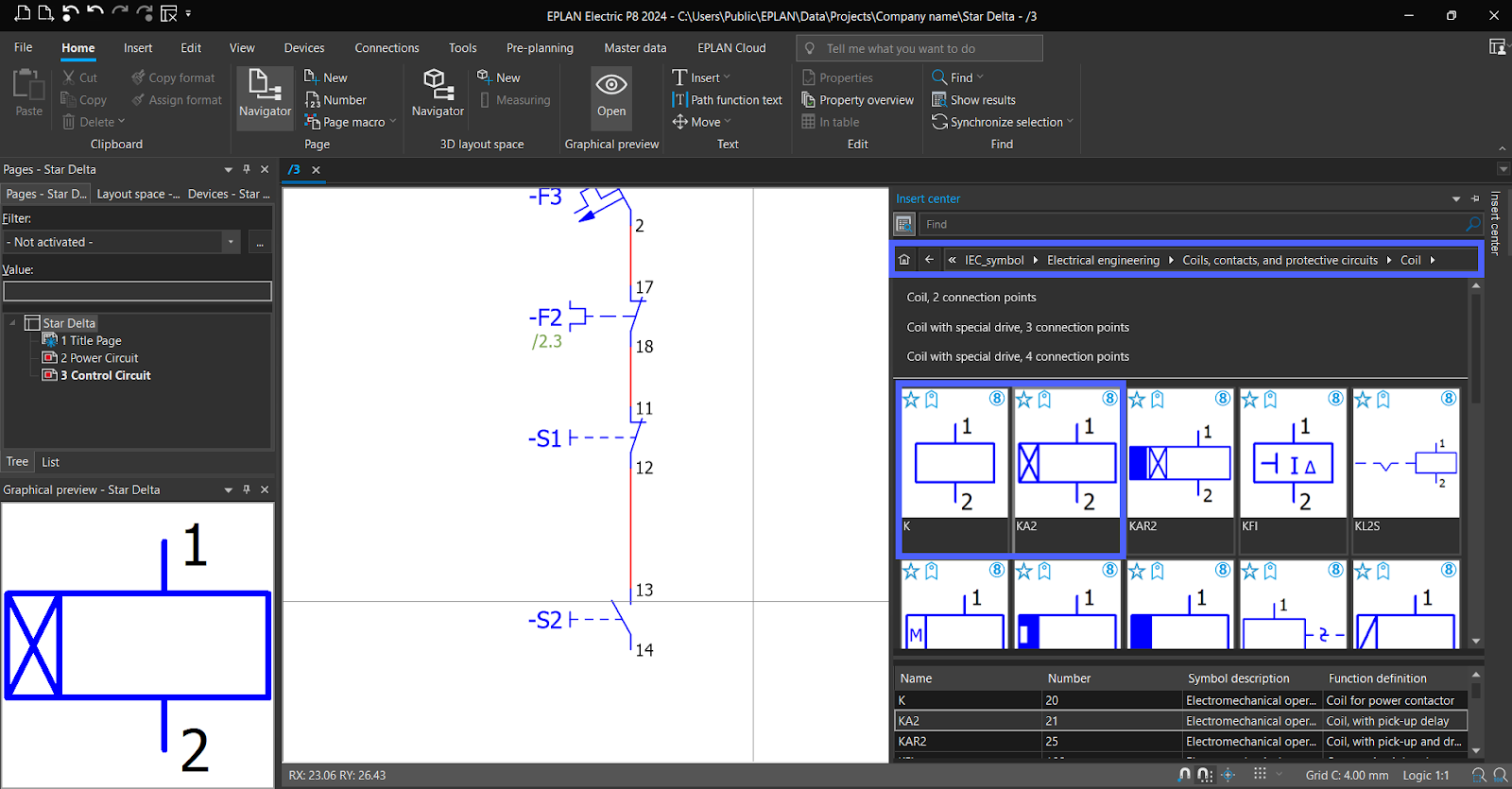
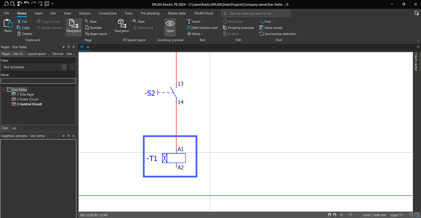
Drag “Timer Coil “to schematic.
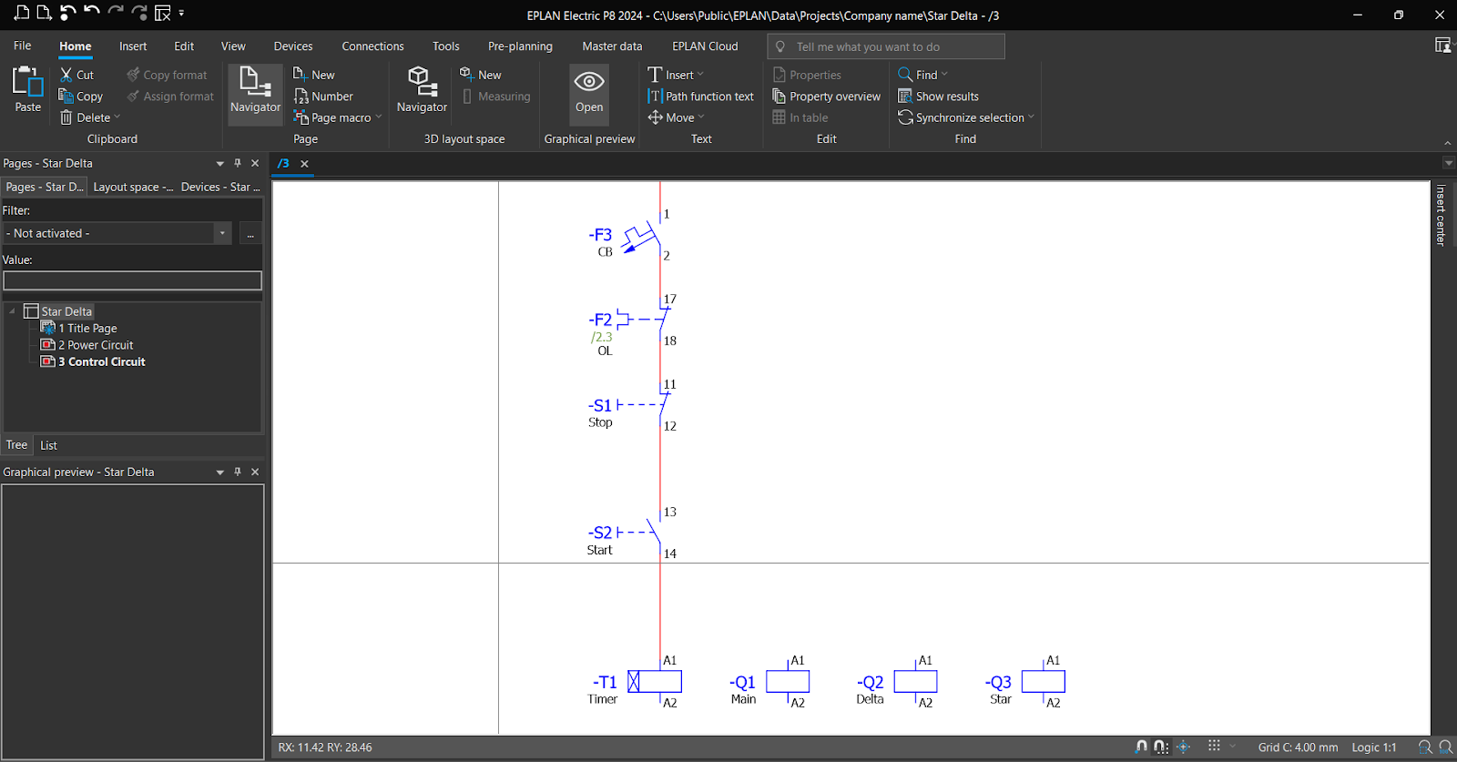
Now Drag Three “Coils “for contactors to the schematic.

Note, make sure to set the coil’s “Displayed DT” to its contacts in “Power circuit page.”

Set “Function text” to elements.
Now, Navigate to the symbols section to find the "NO/NC contacts" symbol for the contactor and Timer.

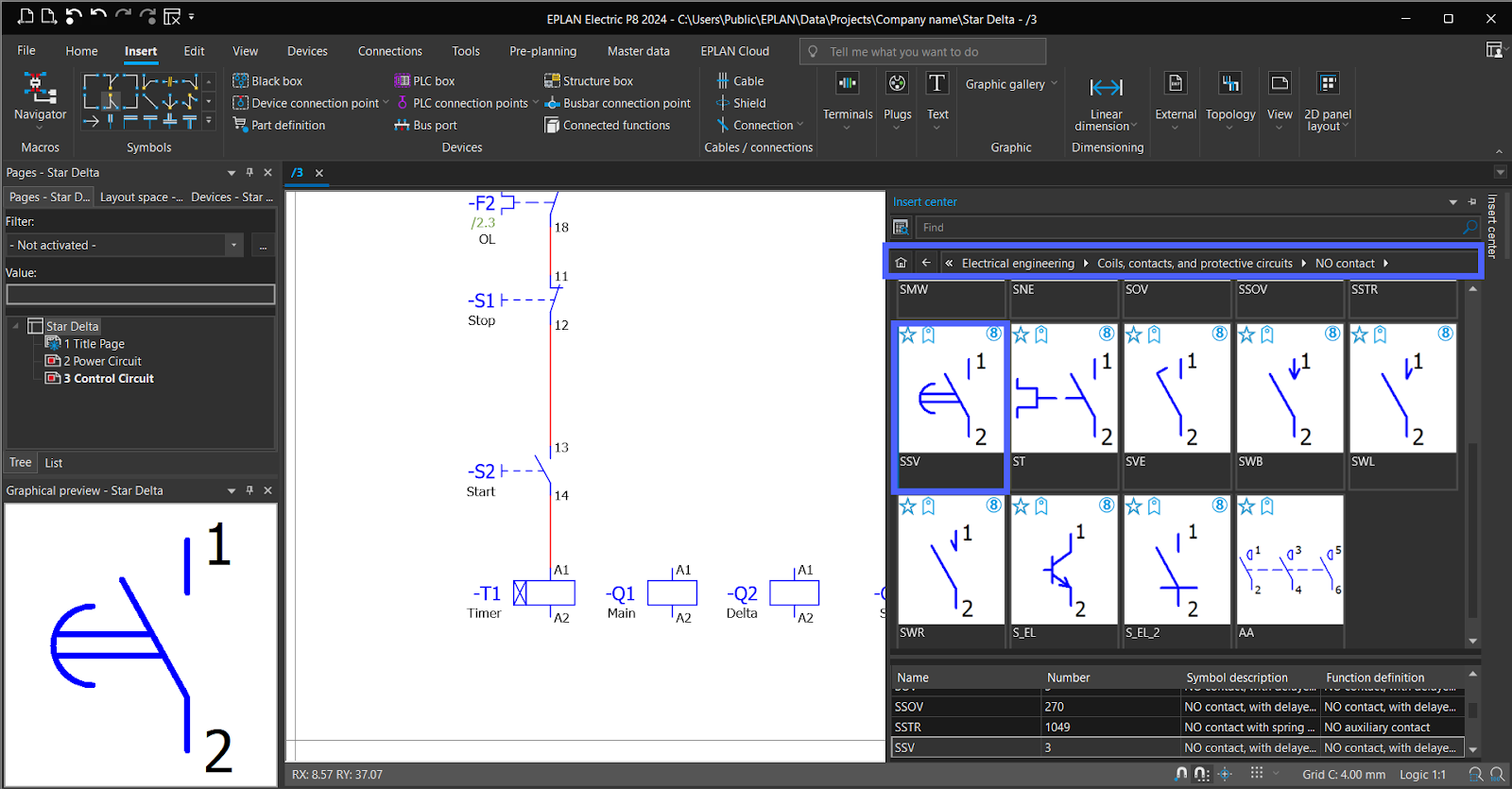
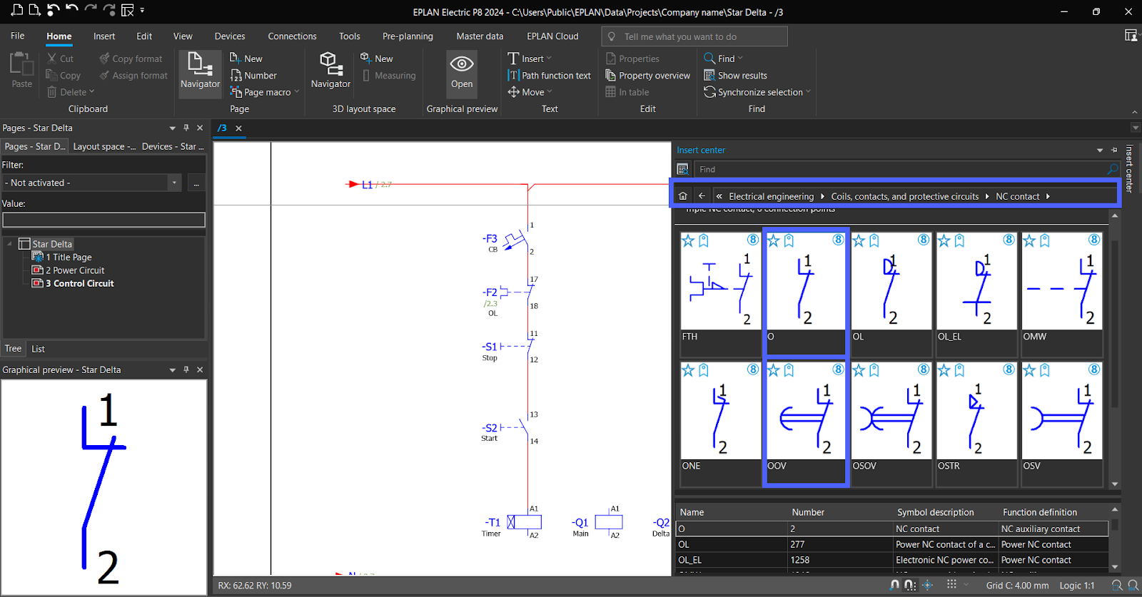
Now drag Two “NO Contact” one for “Main” and other for “Timer”, and three "NC Contact" symbols onto the schematic. Use one for the "Timer" and the others for "Star” and “Delta” interrupt.
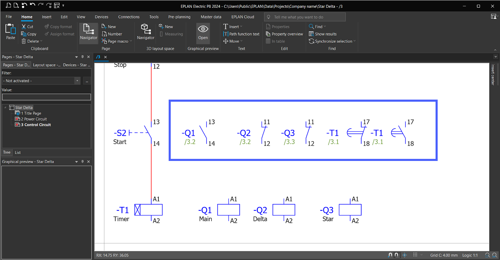
Now both the NC and NO contacts of the timer share the same identification numbers, which are "17" and "18." Simply double click on it to modify its identification numbers.
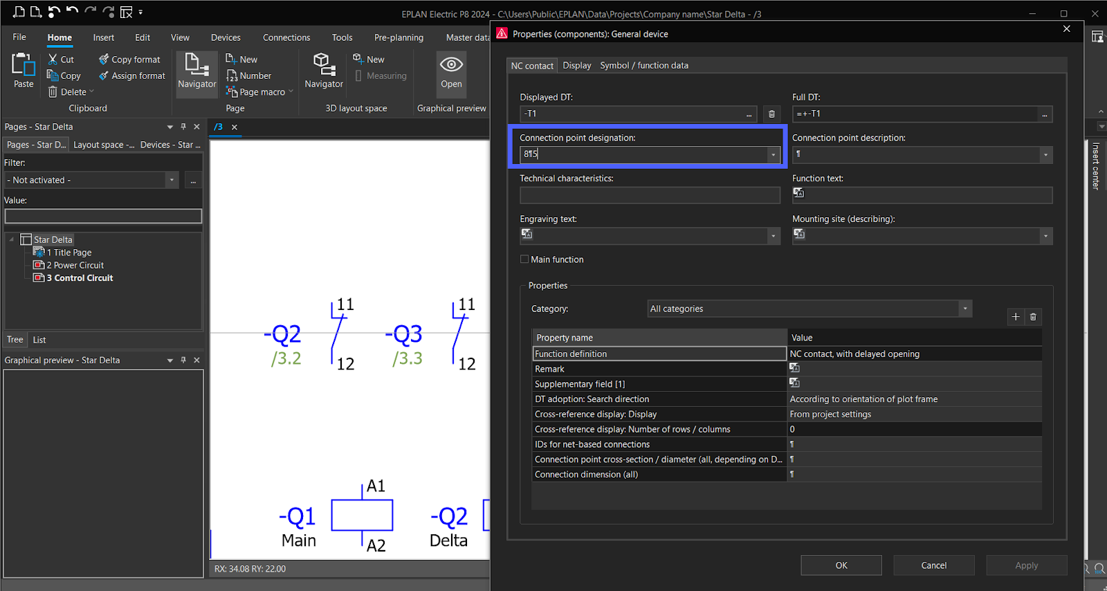
In same way for NO contact.
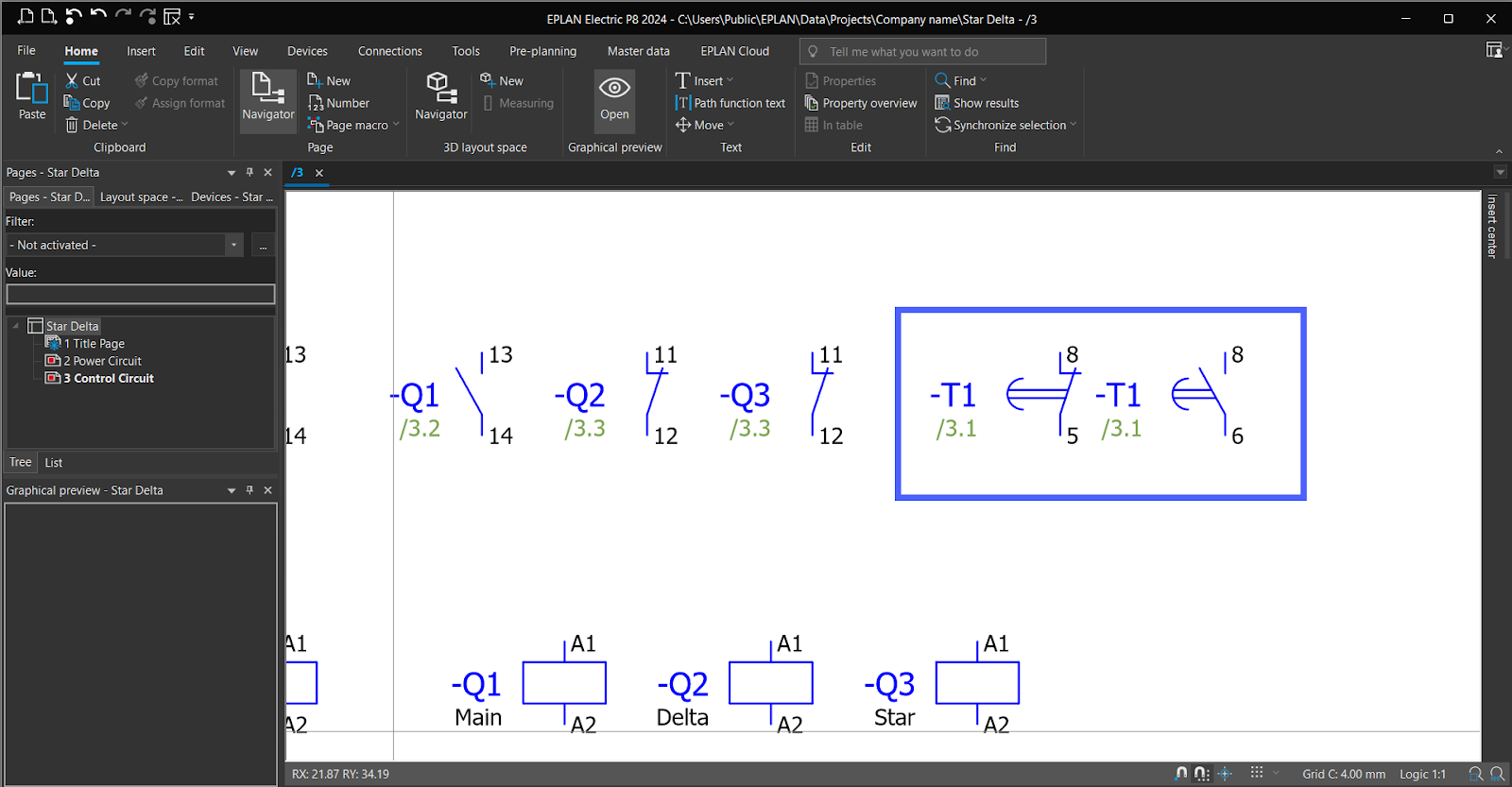
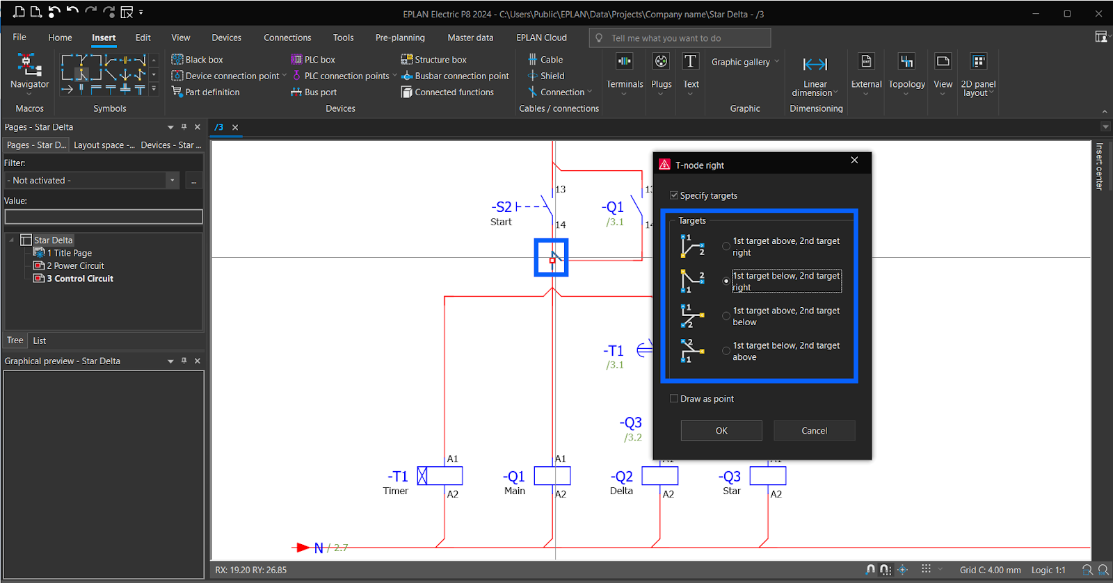
Now connect the control circuit diagram.
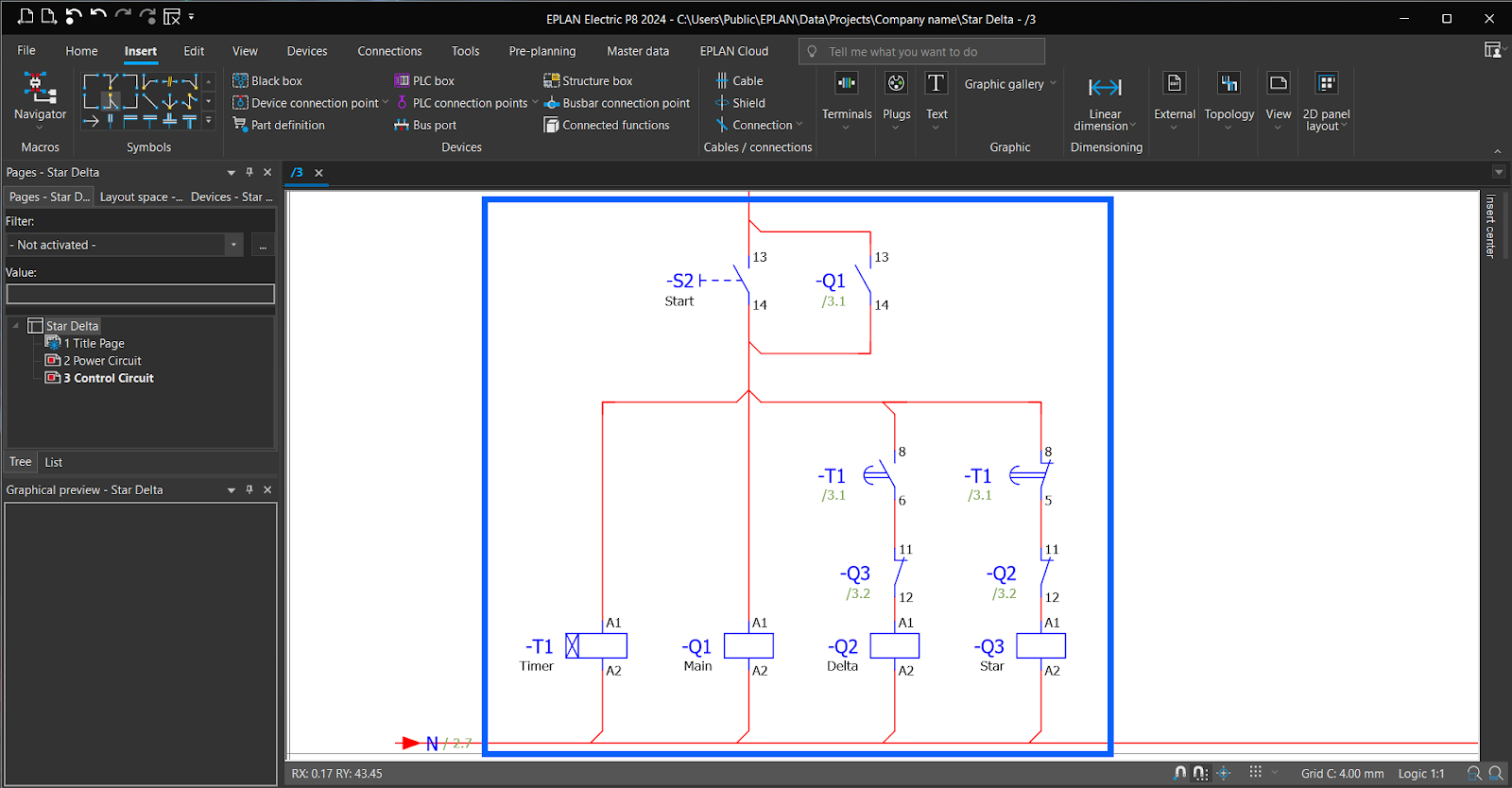
Note, you can adjust the direction of a "T-node" by double-clicking on it and selecting the desired direction.
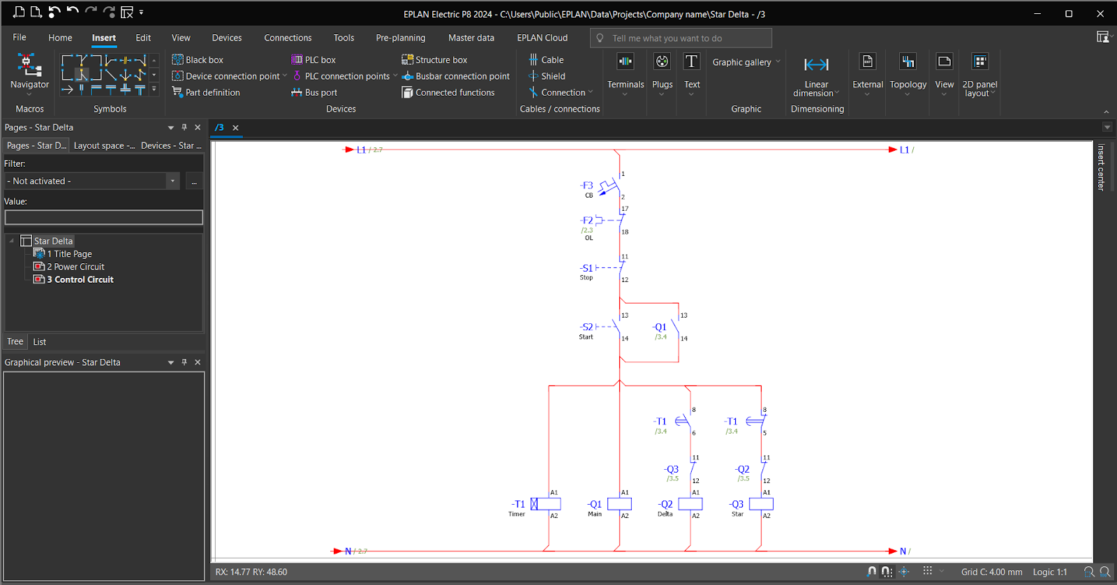
Now all is done.
For this tutorial, we've covered enough ground. In the next tutorial, we will delve into creating tables and inserting parts into symbols for 3D layout. Stay tuned for more exciting insights!
Conclusion
In conclusion, mastering the art of creating precise and efficient electrical panel diagrams is a pivotal skill in electrical engineering and industrial automation. EPLAN, a powerful software solution, empowers you to design these diagrams easily and precisely. In this guide, we've explored the fundamental steps of laying out a basic electrical panel diagram, from navigating the EPLAN interface to crafting the power and control circuit diagrams for a Star Delta starting method.
Whether you're an aspiring electrical engineer, a seasoned professional looking to enhance your skills or a curious mind, this guide equips you with the knowledge and confidence to create efficient electrical panel diagrams. These diagrams are not just blueprints but the foundation of successful automation and electrical design projects.
As you continue your journey in the EPLAN and industrial automation world, remember this is just the beginning. Endless possibilities are waiting to be explored, and this guide serves as your stepping stone to more advanced projects. In our upcoming tutorials, we will delve into creating tables and integrating parts into symbols for 3D layout, opening new dimensions in your learning journey. Stay tuned for more exciting insights and keep expanding your skills in the world of electrical engineering and industrial automation.
