

PNP Sensors Explained: Sourcing Outputs, PLC Wiring & Testing

Introduction
PNP sensors show up constantly in industrial automation, and if you spend any time working with 24V systems, you are going to come across them. The tricky part for most people is wrapping their head around sourcing and sinking. It sounds more complicated than it actually is. So in this tutorial, you are going to cut through the confusion and learn it in plain, straightforward language. You will get into how a PNP sensor actually works under the hood, walk through connecting one to a sinking PLC input, and then grab a multimeter to test the output and make sure everything is behaving the way it should. By the time you are done, wiring a PNP sensor on the job should feel a whole lot less intimidating.
Prerequisites
Having a basic understanding of "NPN Sensors" beforehand will really help you get the most out of this tutorial and follow along more easily.
Industrial 24V Sensor
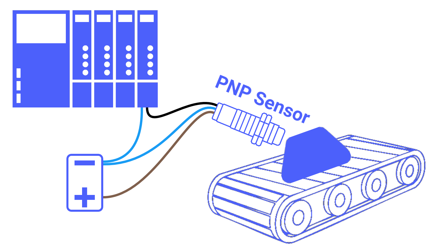
When it comes to automation systems running smoothly, the discrete I/O signals, especially those coming from sensors, are vital. It's through these signals that the systems gain the ability to execute their designed tasks with higher accuracy and fine-tuned precision. For most industrial automation applications, 24-Volt DC is the preferred method due to its enhanced safety and widespread use, which aligns perfectly with the operating voltage of many DC sensors. When you're working with 24-Volt DC sensors, the term PNP is practically unavoidable; it's a key industry term that many find crafty to get their heads around.
Sourcing Output Circuit
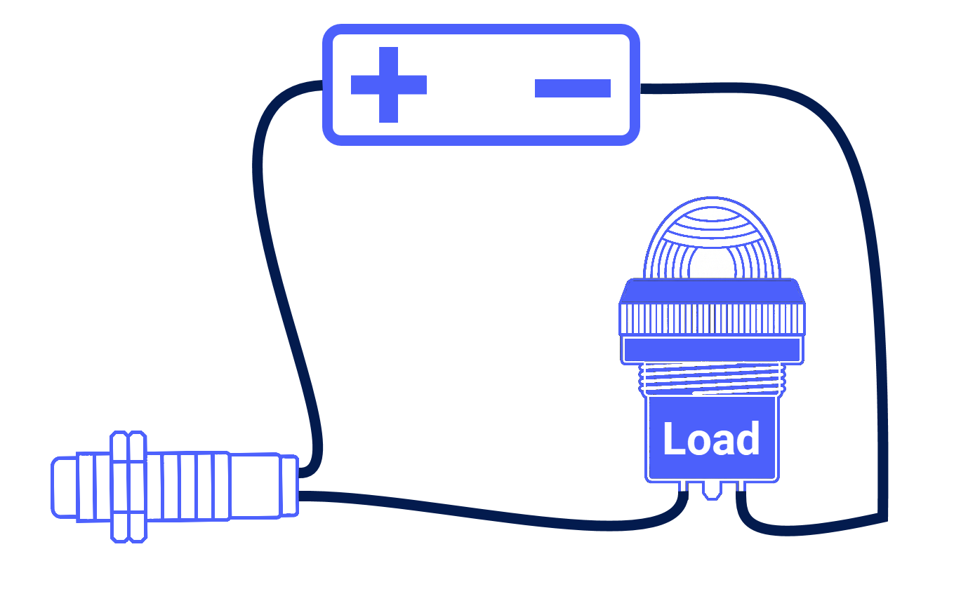
To get started, you need to check whether the circuit you are working with is meant for PNP sensors. To help you understand this, here is a simple DC circuit made up of a power source, a 2-wire proximity sensor, and a pilot light acting as the load.
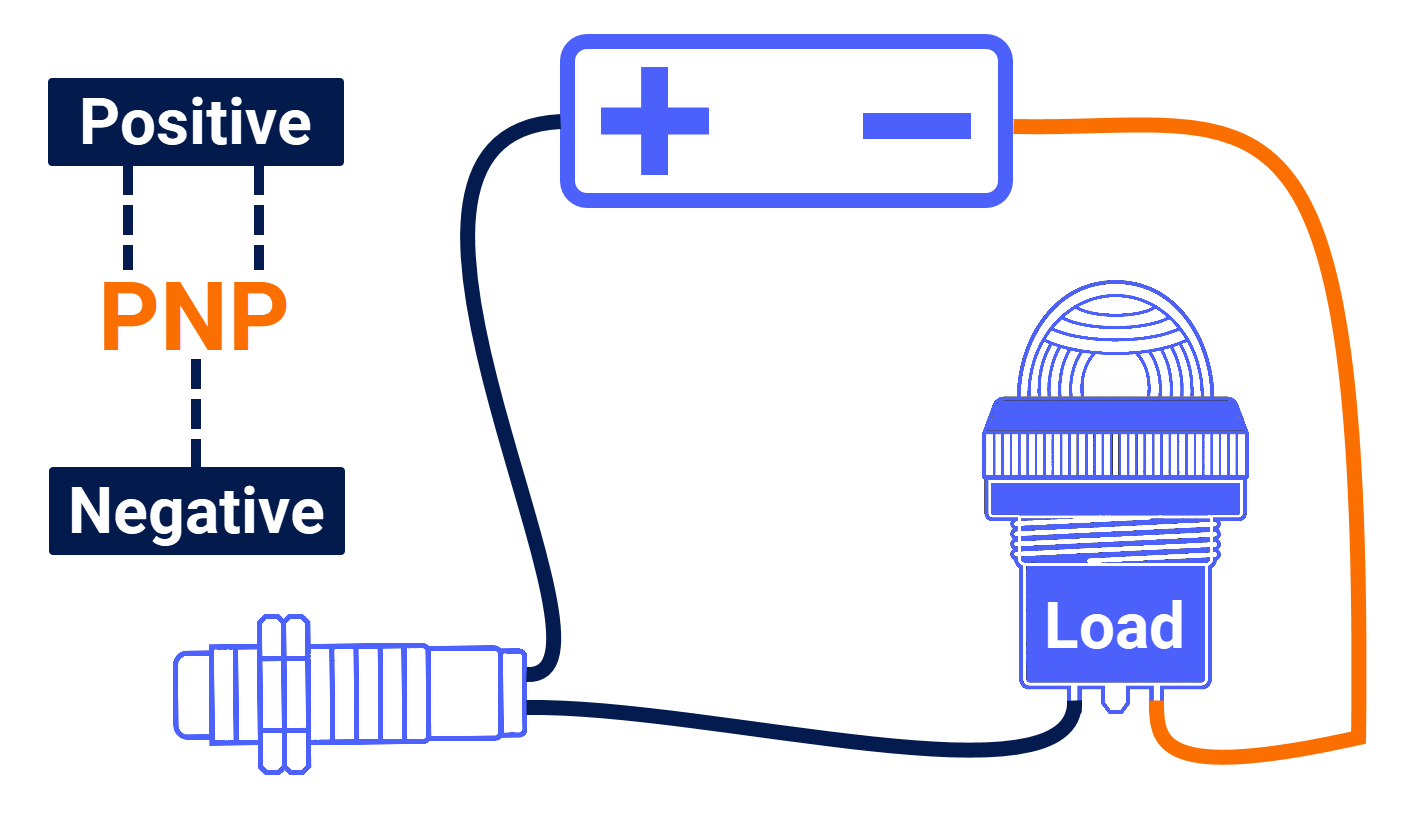
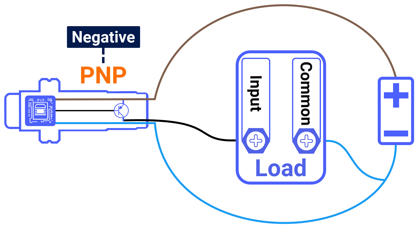
PNP takes its name from the Positive-Negative-Positive. A practical way to remember the correct load connection is to look at the middle letter N, which hints at the Negative side of the power supply. That is where your load should always be connected, and this little trick makes it hard to forget.
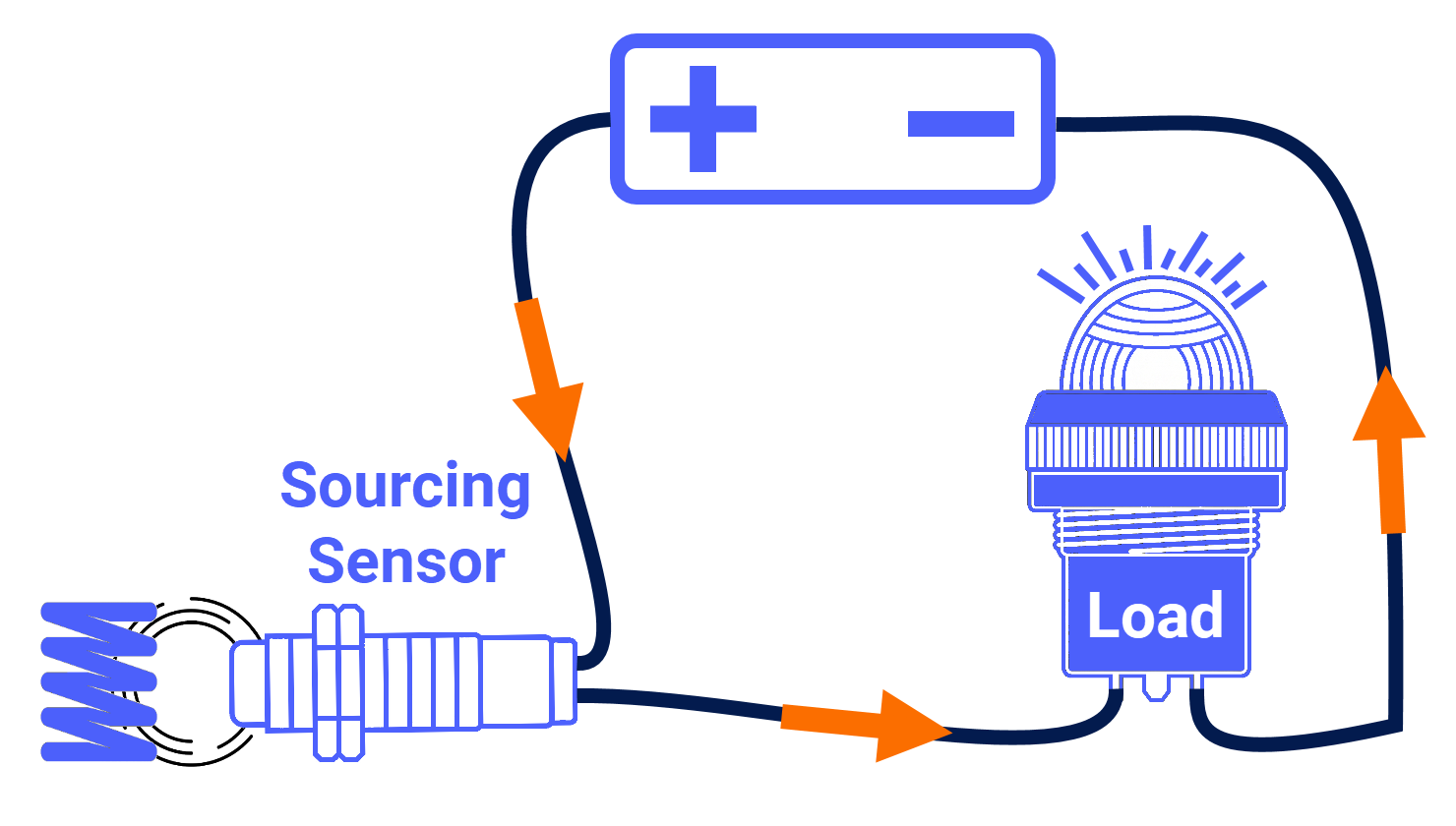
When a target enters the detection range of the 2-wire proximity sensor, the sensor switches on, allowing conventional current to travel from the positive rail of the power supply, through the sensor, then through the load, before returning to the negative terminal of the power supply. You refer to the 2-wire proximity sensor as a sourcing sensor in this circuit because it actively supplies the electrical current that the load requires to operate.
PNP Sensor Schematic
Take a closer look at what is inside a 3-wire PNP sensor. At its core, the sensor typically contains a PNP transistor with sensing circuitry. Although additional components, such as a voltage regulator and signal conditioning circuit, are usually present as well.
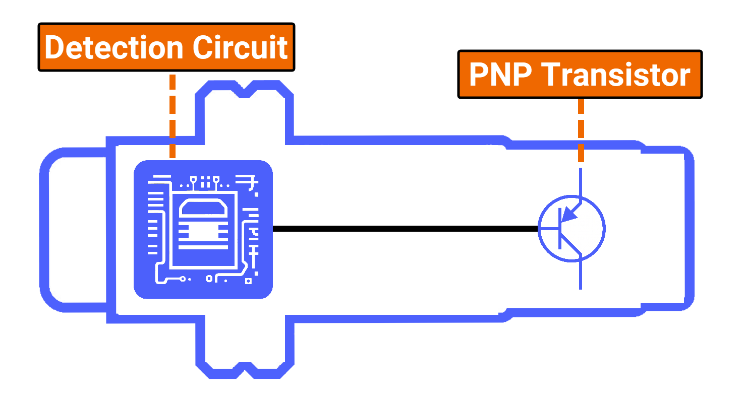
The sensing element circuit has one primary job: recognizing when an object enters the sensor's detection range. Once that happens, it wastes no time and fires a signal over to the PNP transistor, triggering it to switch on.
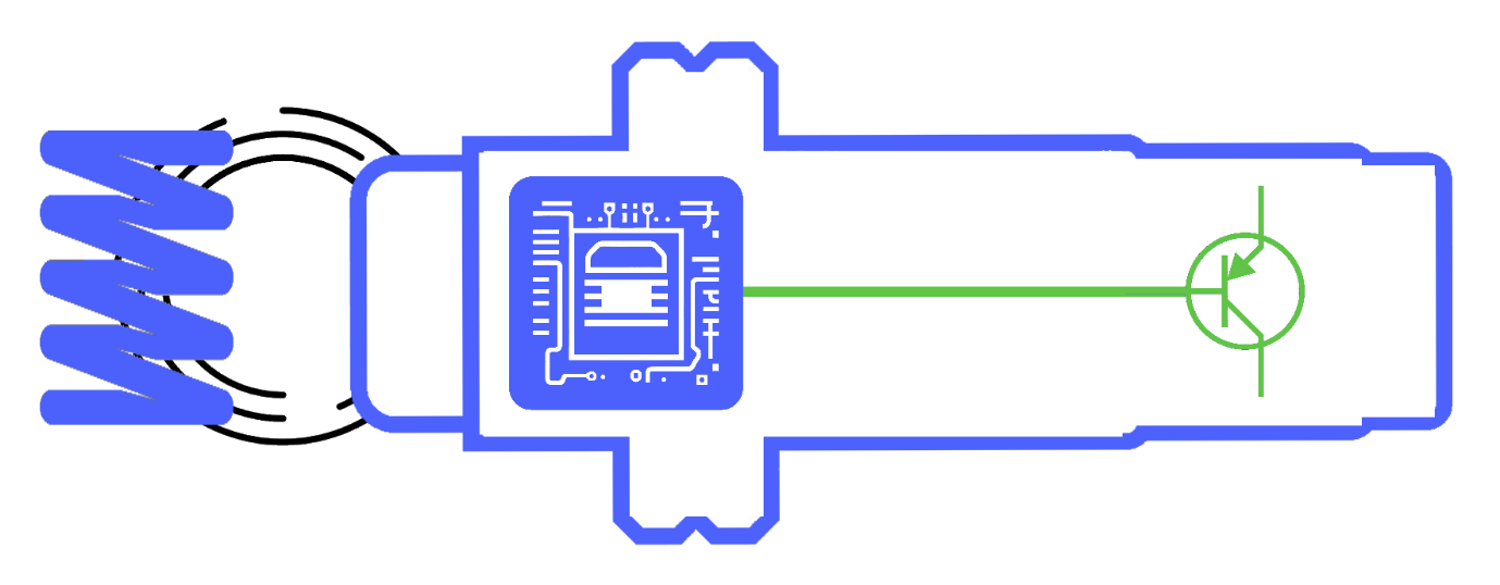
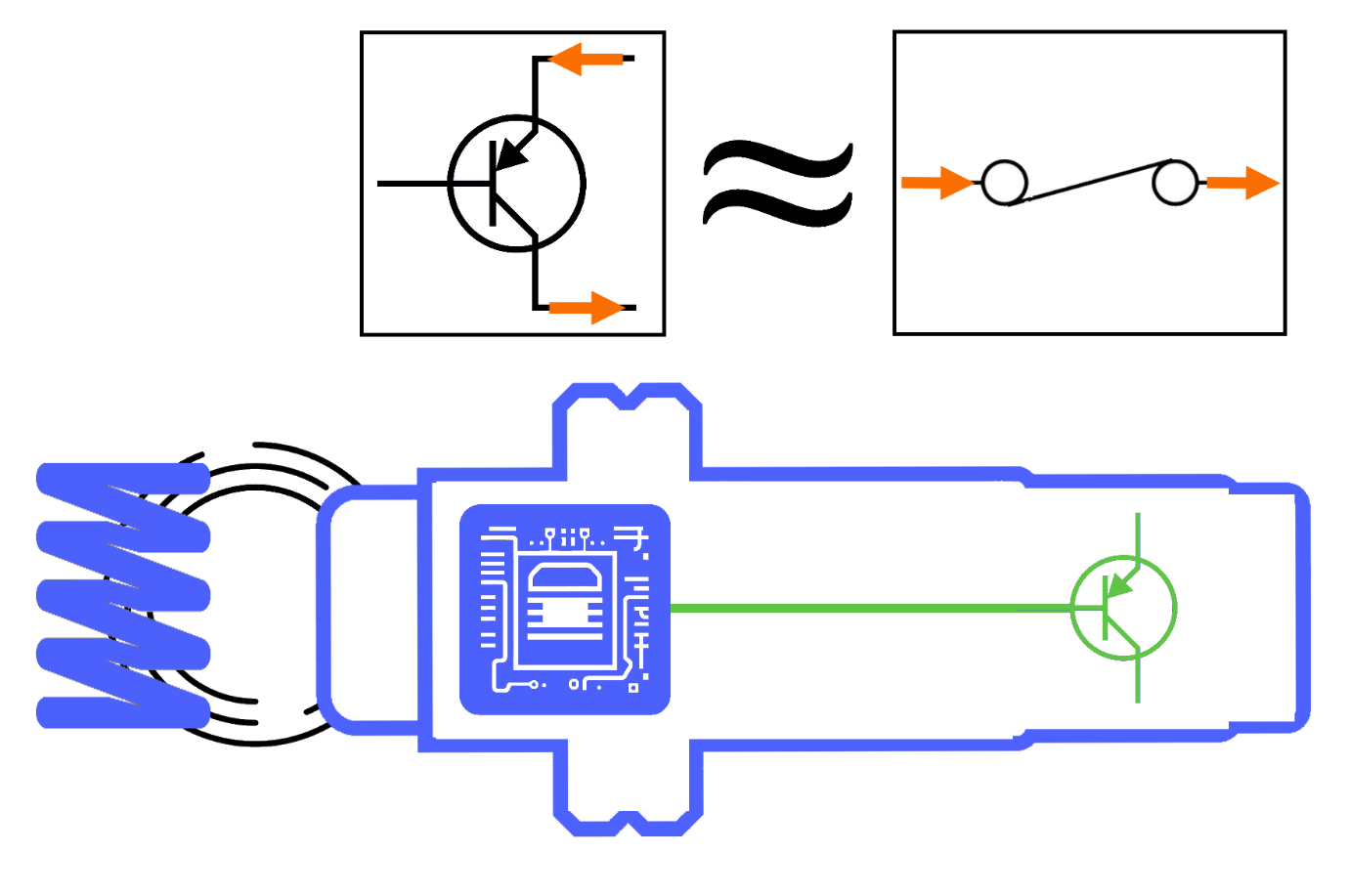
Without going too deep into the electronics, the PNP transistor works much like a switch inside the sensor. It is responsible for controlling the current flowing through the sensor. Once it switches on, it opens the door for current to pass through.
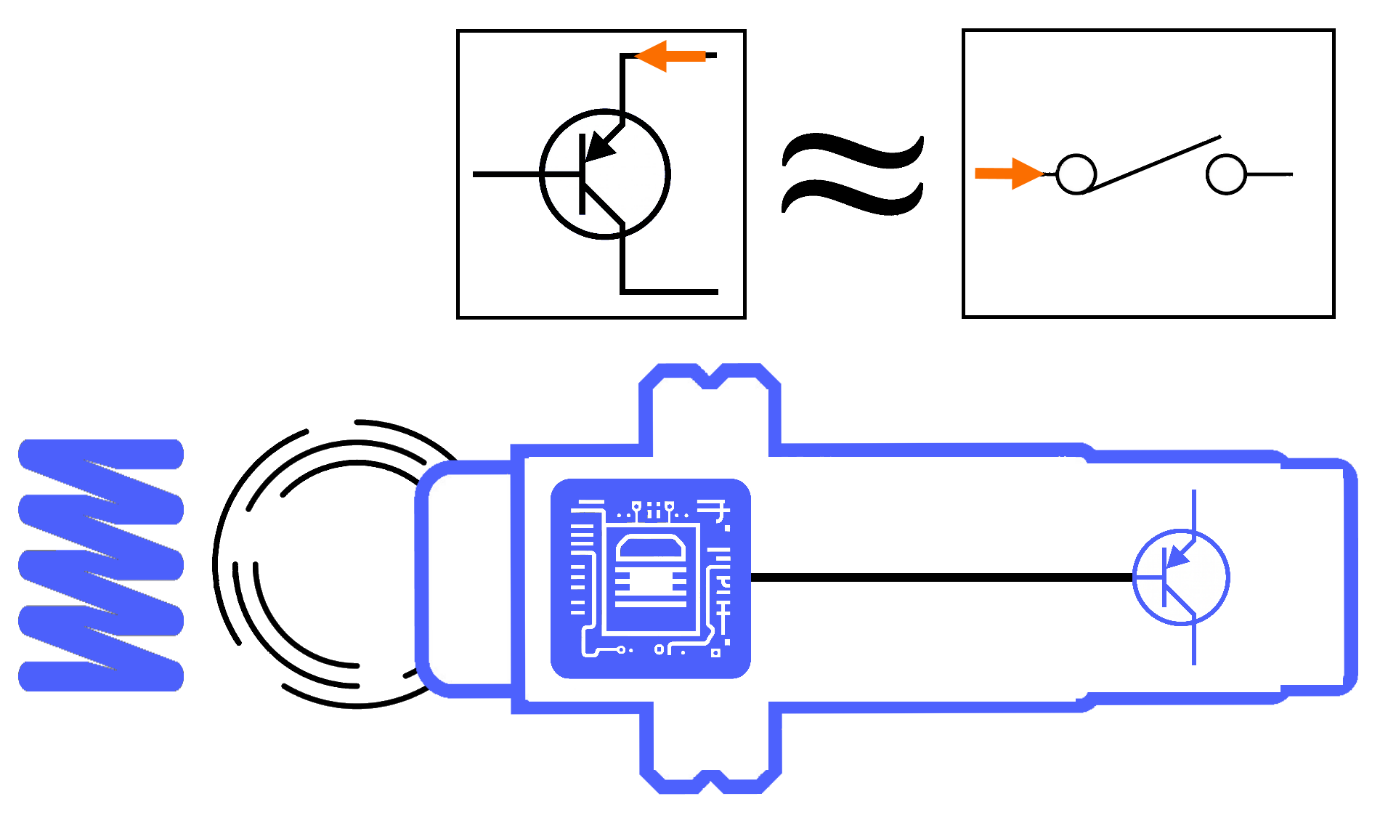
Once it switches off, that current path is shut down entirely.
PNP Sensor Interface
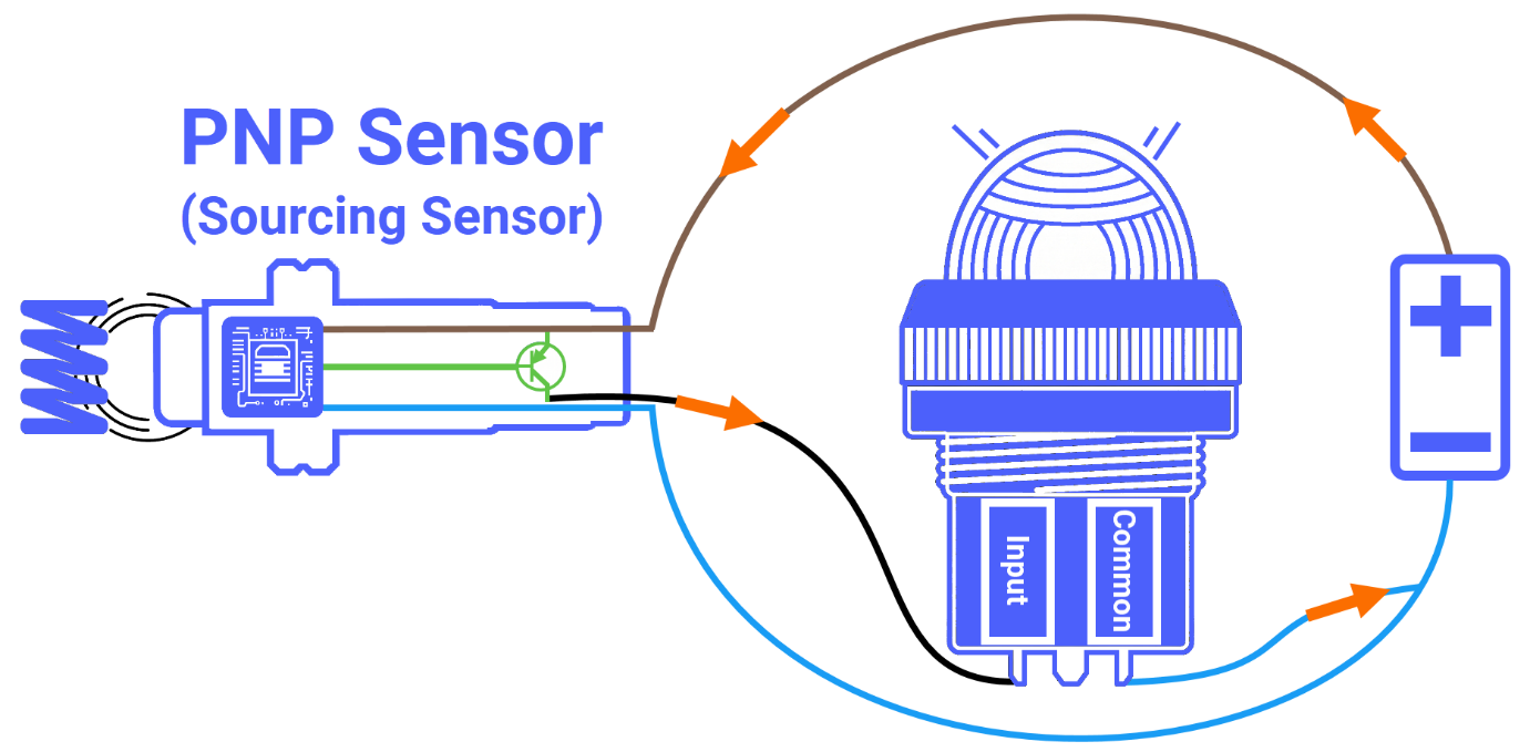
One thing that separates solid-state 3-wire PNP sensors from passive sensors is that they are active devices, meaning they require a small amount of operating power to function properly. Of the three wires coming out of the sensor, two are strictly dedicated to powering it up. The brown wire, commonly referred to as the power wire, connects to the power supply's positive terminal, and the blue wire connects to the power source's negative terminal.
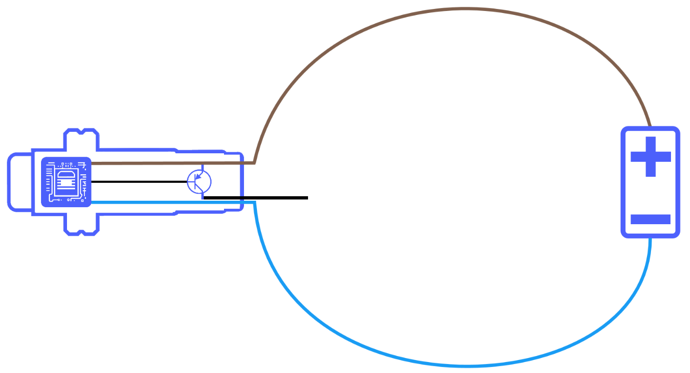
Now, the black wire plays a totally different role from the other two. Instead of dealing with power, it handles signal transmission, connecting the sensor's output directly to the load's input terminal. The PNP transistor is deliberately wedged between the positive voltage wire and the signal output wire, and that comes down to one simple fact: PNP transistors are made for positive switching.
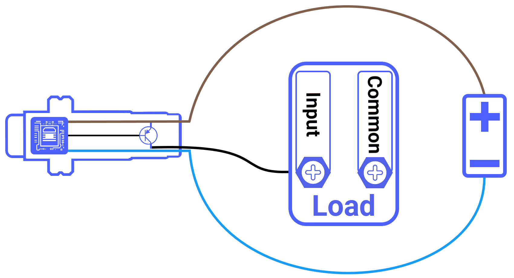
Keep in mind that the middle character in the word PNP is the letter N, and that N is short for Negative, so the negative terminal of your power supply must be electrically tied to the common terminal of the load to close the circuit.
How the PNP Sensor Works
Suppose the load is a 24‑volt DC pilot light. When the PNP sensor does not detect a metal target, its active output is not driven, and the internal PNP transistor is cut off. Electrically, that output wire is essentially high‑impedance, like a switch left open. Therefore, the sensor does not source current into the lamp circuit, so the lamp sees no positive feed through the output and remains off (except for negligible leakage) during the device off state.
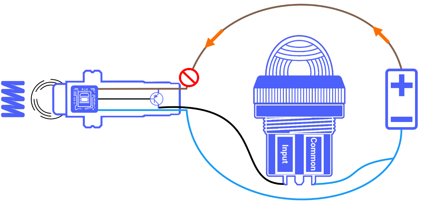
When the sensor detects a metal target, as soon as it enters range, the active line is driven high, which turns the internal PNP transistor on. In that on‑state, the transistor behaves like a closed switch with a small voltage drop. This way, it can source current. Current then leaves the power supply's positive terminal, passes through the PNP output stage to the sensor's output wire, flows through the pilot light or other load, and returns to the supply negative (0 volt). Since the sensor is feeding the load from the positive rail, it's known as a sourcing sensor.
Wiring PNP Sensor to Sinking PLC Input
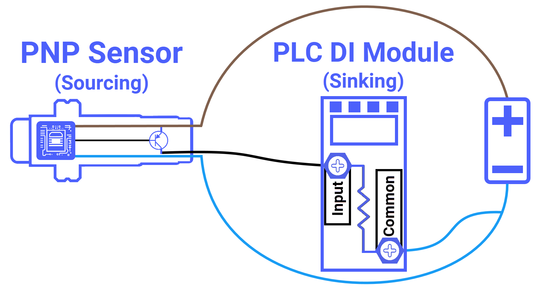
Once you replace the pilot light with a PLC digital input module, you will notice that connecting a PNP sensor to it is not all that different from what you have already seen. The wiring approach remains largely the same, though two important factors deserve your attention before moving forward.
First, it is worth knowing that PLC digital input modules do not all work the same way. They come in either sinking or sourcing types, and this tutorial will focus on the sinking configuration. With a sinking input module, the PLC common terminal is wired to the negative end of the power supply. Also, the input channels inside the module are internally tied to the common ground connection.
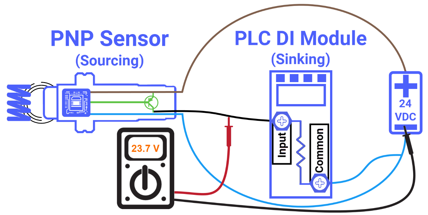
Second, compatibility between the sensor and the PLC input module is something you cannot ignore. In industrial settings, the field sensor and the discrete input module must complement each other, or the whole setup will not work as expected. Because a PNP sourcing sensor is being used here, it needs to be paired with a sinking PLC discrete input module to function correctly. Hook up the black wire (the sensor output wire) to the PLC module's input channel, and connect the negative terminal of the power supply to the module's common terminal to finish off the circuit.
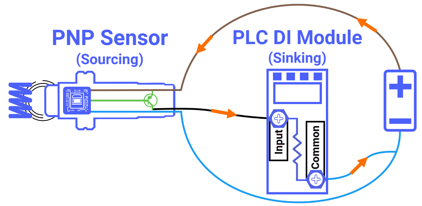
The moment a metal object enters the detection range of the PNP sensor, the sensing element circuit fires a signal to the PNP transistor, switching it on. At that point, the transistor kicks in and acts just like a closed switch. Then, current begins flowing from the positive terminal of the power supply, travels through the sensor, passes through the PLC input channel, and eventually returns to the negative rail of the power supply through the PLC common terminal.
Checking PNP Sensor Output Signal
Testing the PNP sensor is the last piece of the puzzle, and it is simpler than you might think. Pull out your multimeter and bear in mind that the sensor operates on a 24V DC supply for this test. When the PNP sensor is not detecting any metal object within its range, the output voltage is expected to be extremely low, practically zero volts, telling you that the sensor is not pushing any voltage toward the PLC digital input module. Set up the multimeter by touching the red lead to the black wire of the PNP sensor and grounding the black lead. As expected, the multimeter confirms a reading of nearly zero volts, explaining that the sensor is in its resting state.
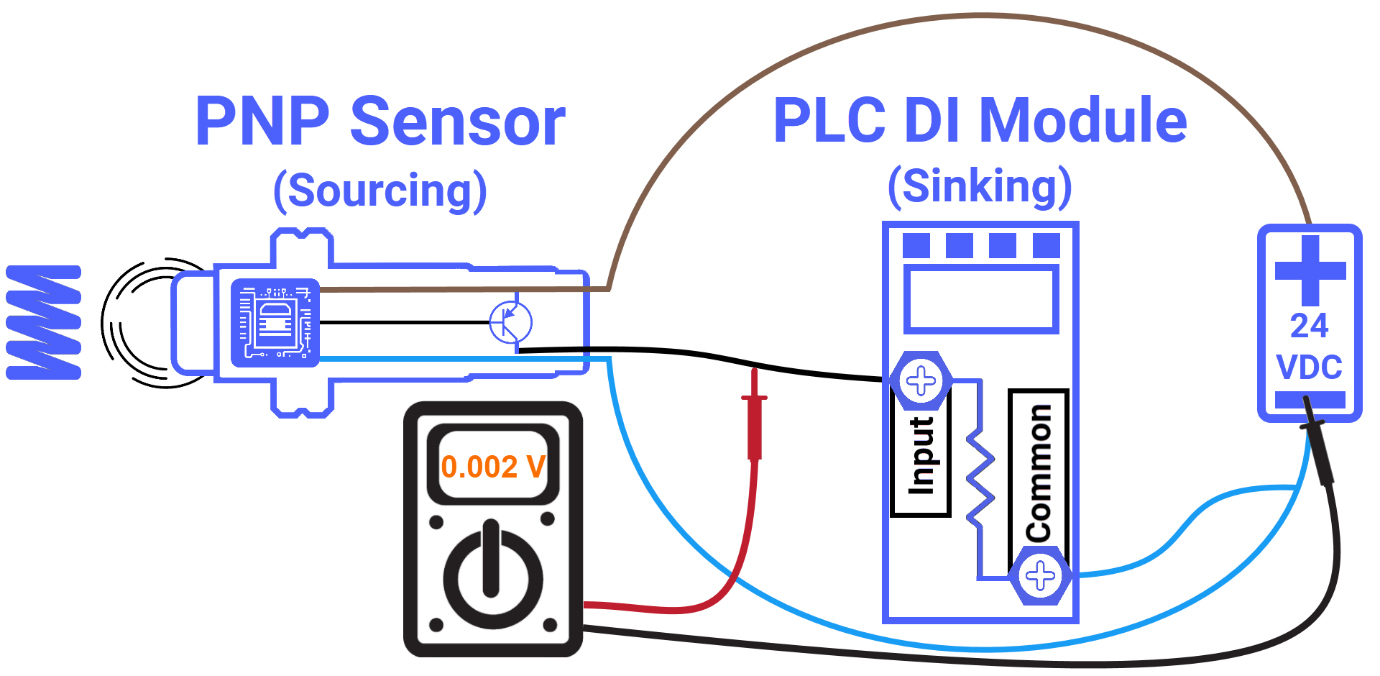
As soon as a metal object is detected within the sensor's range, the PNP sensor output voltage rises and settles at a level very close to the supply voltage. As a result, the multimeter reflects this change immediately. However, it is worth mentioning that the reading will never quite match the supply voltage. The PNP transistor introduces a small but consistent voltage drop, keeping the output always sitting 1 to 2 volts below the supply voltage.
Conclusion
So to wrap things up, you now know what a PNP sensor is and why people call it a sourcing output. You got a look at how that internal PNP transistor essentially acts like a switch, sitting between the positive supply and the output wire and pushing current toward the load the moment it detects a target. You also now know the correct way to hook up a 3-wire PNP sensor to a sinking PLC input. You learned to tie your PLC common to 0V and land that black wire on an input channel. Then, on top of that, you verified everything with a multimeter to see that the sensor was doing exactly what it is supposed to do.


