NPN Sensors Explained: Sinking vs Sourcing, 3-Wire Wiring, and PLC Input Connections

Introduction
If you have ever felt stuck staring at a 24V DC sensor, wondering why your PLC isn't picking up a signal, you aren't alone. The jump from theoretical electronics to a real-world industrial cabinet is where most people get tripped up, especially when it comes to NPN logic. This guide is built to clear the fog. You are going to explore how "sinking" outputs actually work, look at the internal transistor logic, and walk through the exact wiring standards you will meet on the job. Whether you are a student or a technician, mastering NPN sensors is one of the first steps toward becoming an expert in automation.
Industrial 24V Sensor
Because numerous DC-powered sensors are specifically engineered to operate within this particular electrical range, utilizing 24-Volt DC has become a globally recognized and more secure selection for the majority of modern industrial automation applications. As you work with 24-Volt DC sensing equipment, the term NPN will likely appear quite often. However, understanding its practical application and wiring is challenging.
Sinking Output Circuit
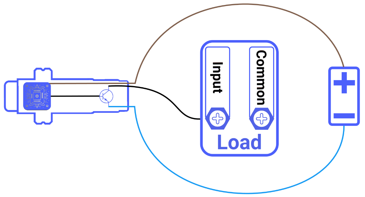
As a preliminary step, you should always determine if the existing circuit design is engineered to support NPN-style sensors. This concept is understood by examining the following basic DC setup, which includes a voltage unit, a two-lead proximity detector, and a connected output device, such as an industrial siren.

Technically, NPN is a condensed way of saying negative-positive-negative. The P located in the center of the acronym stands for Positive polarity and functions as a memory aid, highlighting that the electrical load is always connected to the positive terminal of the voltage unit, essentially waiting for the sensor to provide a ground.
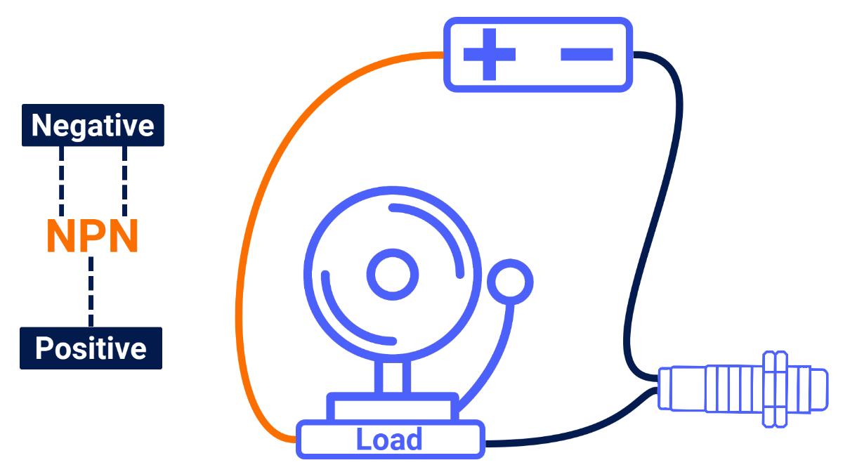
Sensing of an object by the two-lead proximity sensor causes conventional current to depart from the positive supply terminal, pass through the load, and enter the sensor's input wire. It then proceeds through the sensor's internal switching mechanism and exits through the output lead toward the negative supply terminal to complete the electrical loop. When a sensor is wired so that it pulls current through an output device and discharges it into the negative terminal of the voltage unit, as this 2-wire proximity sensor does, it earns the technical designation of a "Sinking Sensor" for that specific circuit.
NPN Sensor Schematic
Usually, the interior electronic design of a three-wire NPN-style sensor is divided into two major functional parts: the circuit responsible for target detection, and the NPN transistor, which serves as the solid-state switch for the circuit.
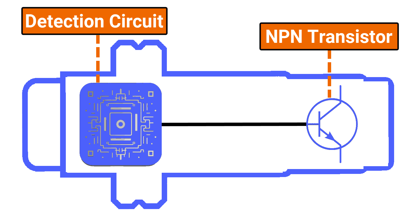
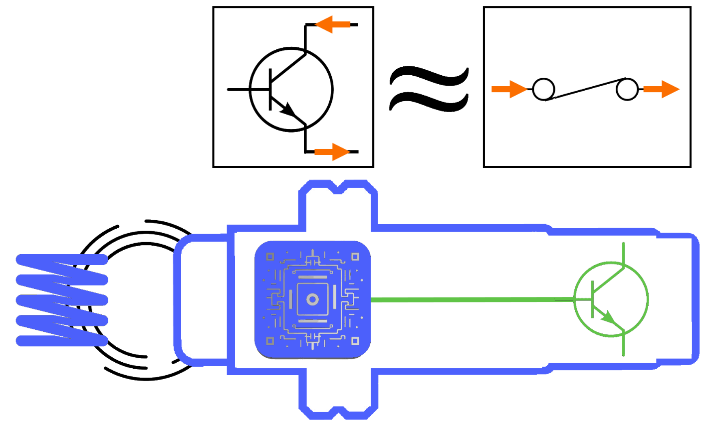
The primary role of the detection circuit is to perceive the presence of any target located in the sensor's vicinity. When such an object enters the active sensing range, the detection circuit promptly delivers a command signal to the NPN transistor, causing it to switch on.
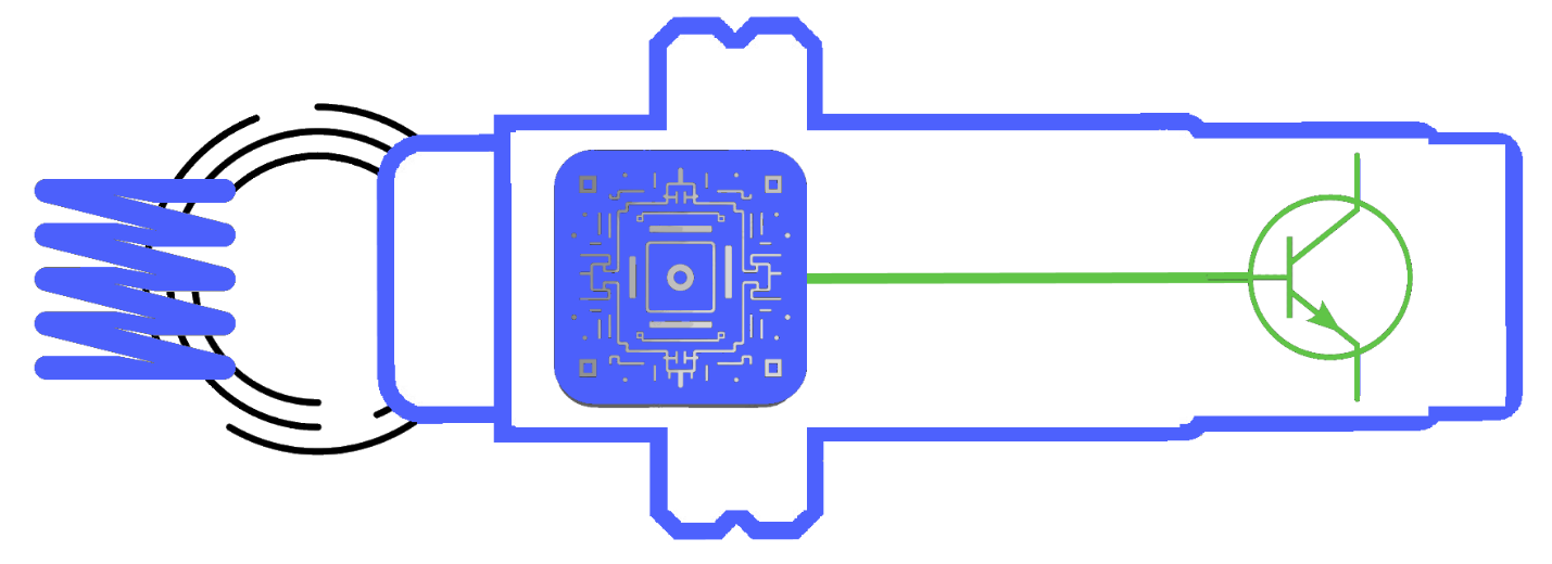
It is helpful to conceptualize the NPN transistor as an electronic switch that regulates the movement of current throughout the sensing device. While the transistor is in its active or "ON" state, electrical current is permitted to travel through the sensor.
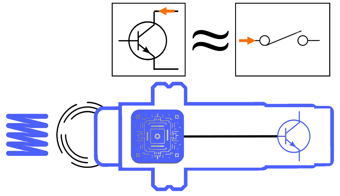
But when it is switched off, the internal current path is effectively broken.
NPN Sensor Interface
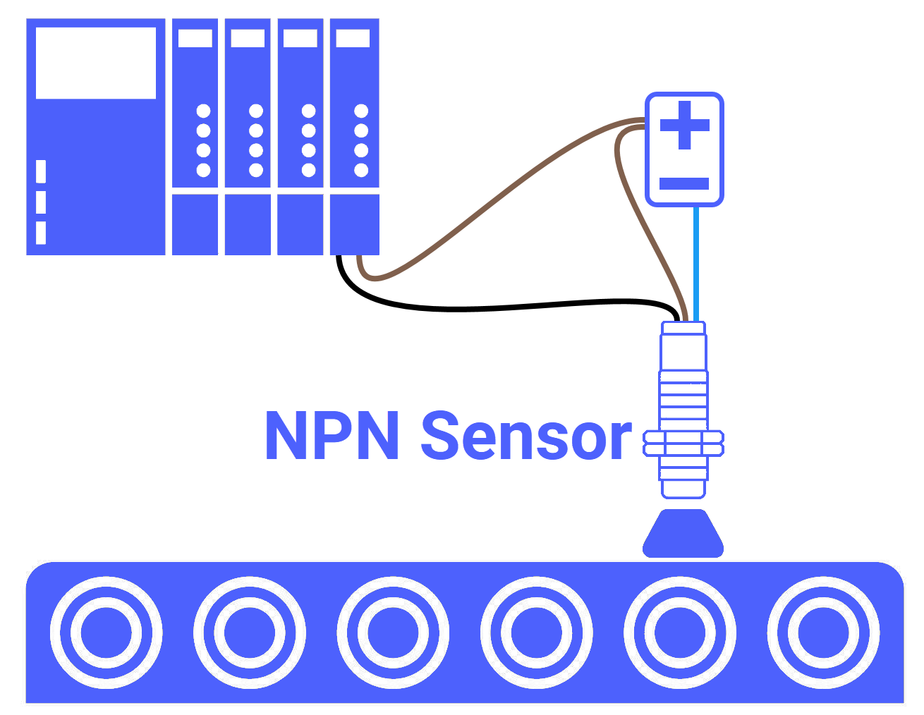
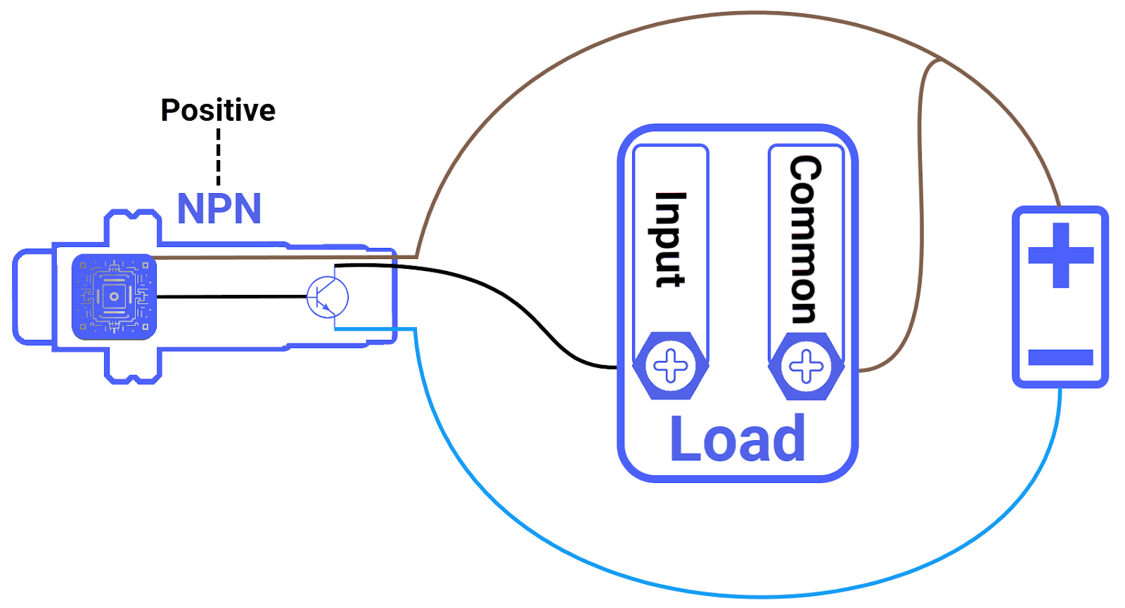
Generally, 3-wire NPN solid-state sensors require a stable power feed because they are active electronic devices, which sets them apart from basic passive sensors. Out of the three-wire interface provided, a pair of leads is dedicated exclusively to delivering the necessary DC power to energize the sensor hardware. The conductor designated for power, which is easily recognizable by its brown insulation, must be linked to the positive terminal of the DC power source; meanwhile, the blue conductor is intended to be secured to the negative terminal or common point of the power supply.
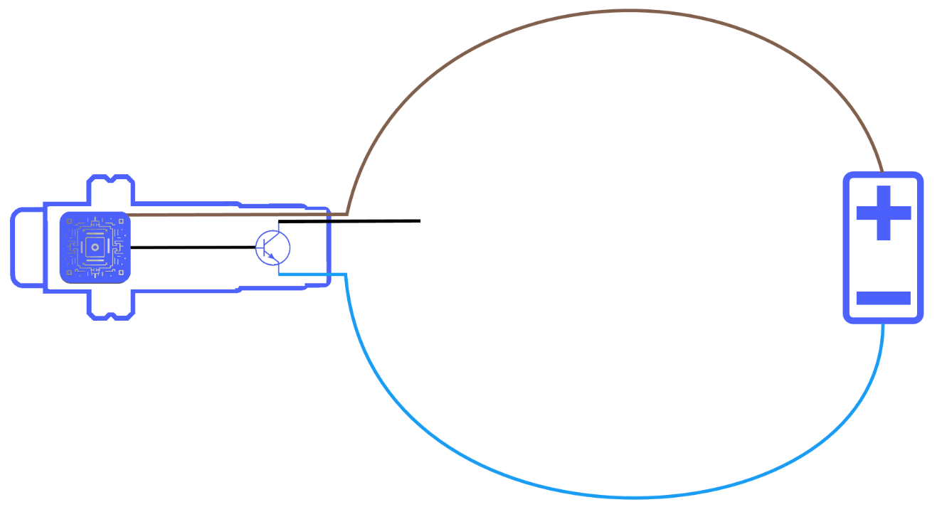
The conductor designated for the signal output, which is intended to be wired directly to the input terminal of your specific load, is easily recognizable by its black insulation. Negative switching is achieved in an NPN sensor because the internal NPN transistor is wired as a bridge between the negative power supply line and the sensor's black signal output wire.
As a helpful mnemonic to assist your recall, the central letter P within the NPN acronym represents Positive, which reminds you that the shared terminal of the load must be wired to the positive rail of the voltage source to complete the electrical loop.
How an NPN Sensor Works
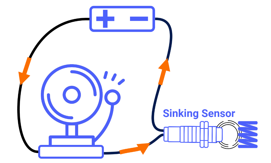
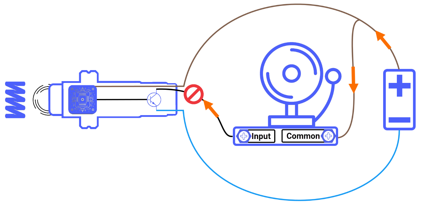
To better illustrate the internal mechanics of a three-wire NPN sensor, you can analyze a practical scenario where an industrial siren acts as the load, providing a clear visual and auditory example of how the circuit completes.
If the NPN sensor does not perceive a target, its internal detection circuitry sets the active signal line to low, causing the NPN transistor to transition into an "OFF" state that mimics an open mechanical switch. Because the output circuit is now broken, no current can sink through the transistor to the negative rail, which leaves the industrial siren without power and completely silent.
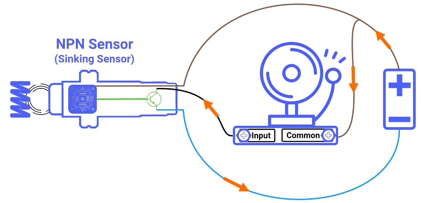
When the NPN sensor detects an object within its range, the internal signal line is driven high, prompting the NPN transistor to turn on and mimic a physical closed contact, thereby completing the circuit path and allowing the siren to sound. As a result, the wiring configuration enables current to originate at the positive side of the DC supply, flow directly through the connected load, and enter the NPN transistor's switching path, which ultimately directs the electrical energy back to the negative rail of the supply to complete the circuit.
Because the NPN sensor accepts the electrical current returning from the load and channels it directly into the common ground, it is universally recognized as a "Sinking Sensor".
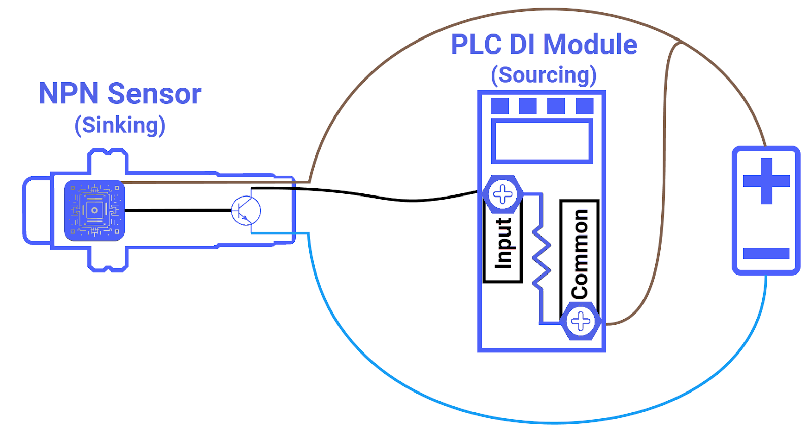
Wiring NPN Sensor to Sourcing PLC Input
If you decide to replace the industrial siren with a PLC digital input module, the fundamental steps for wiring the NPN sensor remain identical. Nevertheless, there are two technical factors you must consider to ensure the correct functionality of the sensor and the PLC module.
First, it is vital to recognize that PLC digital input modules are generally available in two different wiring formats: "Sinking" and "Sourcing" types. In this tutorial, you are presented with a summary of the Sourcing configuration, which is the necessary counterpart for the NPN sensor. When utilizing this setup, you must connect the PLC's shared common terminal to the positive side of the voltage unit, which effectively ensures that the input channels within the module are internally referenced to the positive voltage rail for signal detection purposes.
The second factor involves verifying that your chosen sensor is electronically compatible with the PLC module in use for flawless operation. Successful integration depends on selecting a field sensor that acts as the functional counterpart to the PLC module. Whenever the NPN or Sinking sensor is chosen, it becomes a technical requirement to implement a Sourcing PLC digital input module. You must connect the sensor's signal output, which is the black conductor, directly to the designated input channel on the PLC module.
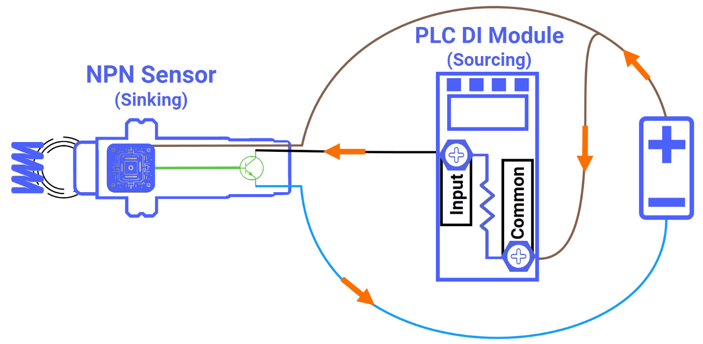
Upon the sensor's target detection, the primary sensing circuitry generates an electrical signal to switch on the NPN transistor. As a result, electrical current departs from the positive side of the DC source and enters the PLC via its shared common terminal. It then traverses the specific input channel before moving toward the NPN transistor, and at last, it reaches the power supply's negative rail to complete the loop.
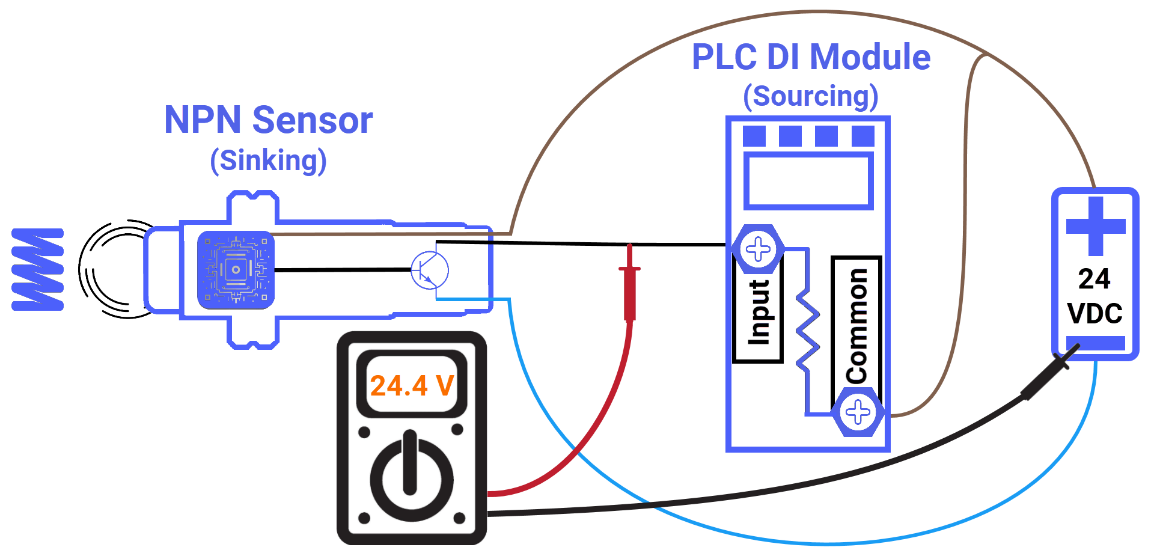
Checking NPN Sensor Output Signal
Lastly, you will explore the proper methodology for verifying the operational integrity of the NPN sensor using a multimeter.
When the NPN sensor fails to identify a target, the resulting voltage at the sensor's output remains at a high state, signifying that the device is delivering a voltage level that is almost identical to the voltage unit. At this point, put the multimeter to use by securing the red probe to the black output wire of the sensor and grounding the black probe. As your earlier prediction suggested, the display on the multimeter confirms a voltage level equivalent to the voltage provided by the power supply.
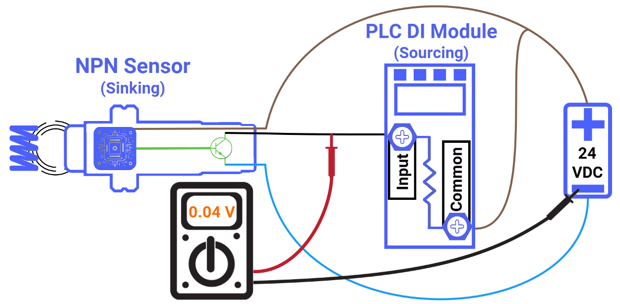
When a target successfully enters the detection zone of the NPN sensor, the expectation is that the output voltage will be effectively shunted to ground, resulting in a reading of nearly zero volts. Just as you predicted, the multimeter will display this low voltage reading.
Conclusion
In conclusion, you have learned that the NPN sensor is far more than just a simple switch. It is a precision solid-state component that defines the current flow of your entire control loop. By exploring the "Sinking" relationship, you now know how to properly pair these sensors with Sourcing PLC inputs to prevent hardware conflicts. You've also gained the practical skills to identify wiring by color and use a multimeter to verify that your voltage drops exactly when it should.
