WinCC Unified Faceplate Tutorial: Build a Reusable Motor Faceplate in TIA Portal Using UDTs and Dynamic SVGs

Introduction
If you've spent any time in TIA Portal, you know how tedious it is to manually tag dozens of identical motors or valves across multiple screens. It's a waste of time and a massive source of errors. The solution is moving away from static objects and using WinCC Unified Faceplates. In this tutorial, you are going to learn how to build a modular motor component that links directly to your PLC UDTs. You will walk through the entire process, from setting up dynamic SVGs to automating the tag connections. The goal here is to help you build a library-based project that is actually manageable, so when you need to make a change, you do it once in the library instead of fifty times on your screens.
Defining Graphic Type
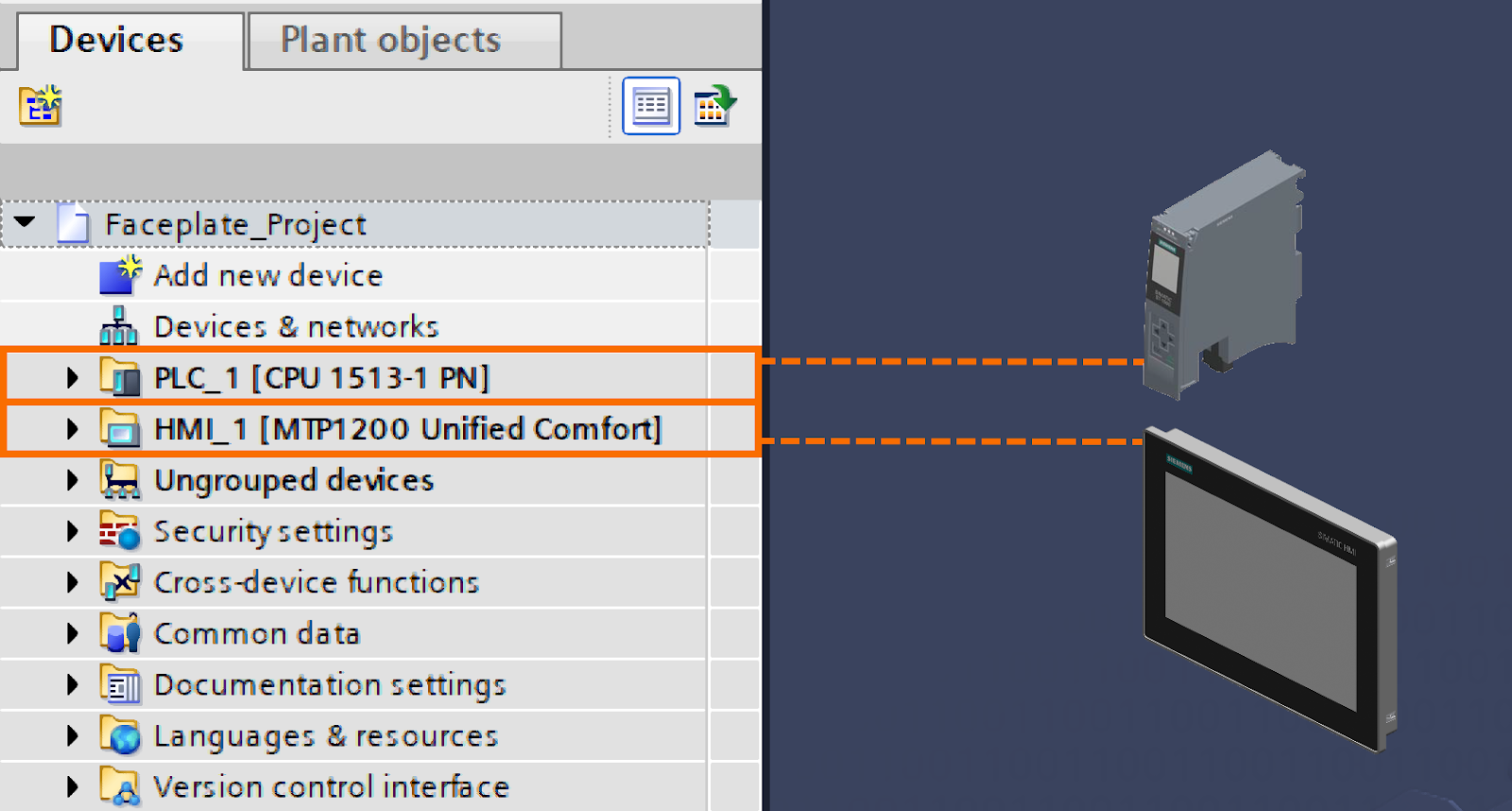
To begin this tutorial on WinCC Unified, start by setting up the fundamental hardware configuration within the TIA Portal environment. After you have successfully initialized a new project, the first step is to establish the hardware framework. You must add the "CPU 1513-1 PN" to serve as your Programmable Logic Controller (PLC) and select the "MTP1200 Unified Comfort" panel as your Human Machine Interface (HMI) device.
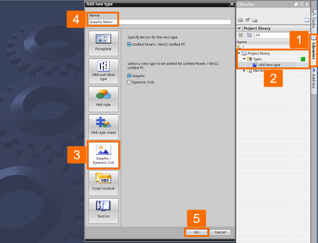
Once the hardware is in place, focus on defining a new Graphic Type within the Project Library. Navigate to the "Libraries" tab located on the right-hand side of the software interface. Expand the "Types" folder found under the "Project Library" section, and double-click the option labeled "Add New Type" to initiate the creation process. A configuration window will appear, prompting you for details. Here, you should select the "Graphic/Dynamic SVG" tab to specify the nature of the type. Name this new type "Graphic Motor" to keep your project organized, and confirm by pressing "OK".
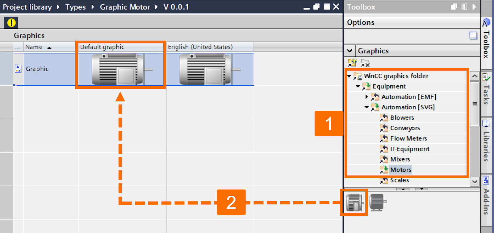
The next phase involves importing the actual visual assets. You will need to drag and drop a graphic from the "WinCC Graphics Folder" directly into your newly created "Type". Specifically, locate the "Motors" category under the "Automation [SVG]" folder. Choose your preferred "Motor" icon from this list and drag it into the "Default Graphic" section of the work area.
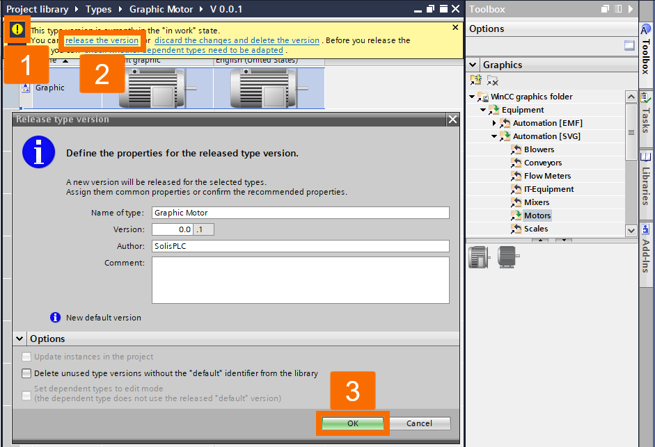
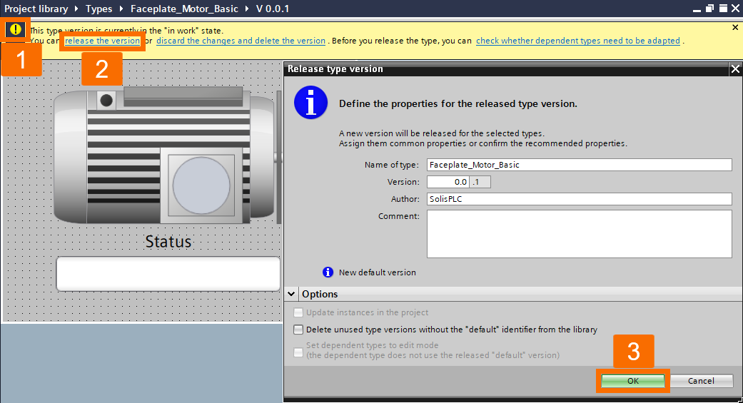
You must release the version to finalize this graphic type for use in other components, such as faceplates. To do this, click the yellow exclamation mark icon indicating a work-in-progress and select "Release the Version" from the context menu. When the confirmation window opens, hit "OK" to complete the versioning process.
Defining UDT
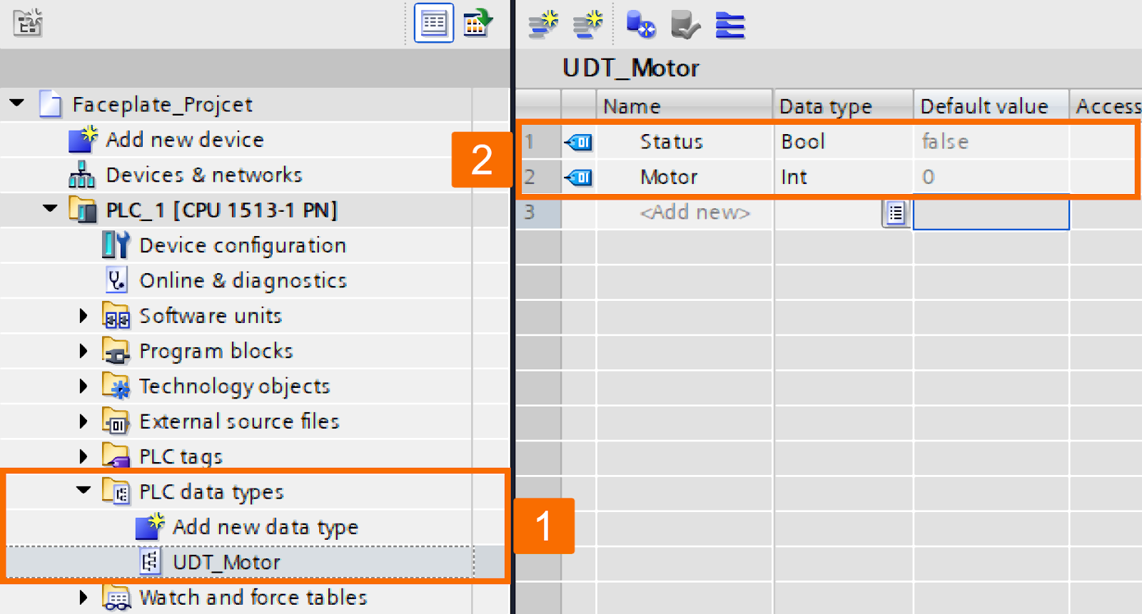
Next, continue by defining the User Data Types (UDT), a critical step for structuring data within the PLC. Within the "Project Tree" on the left, navigate to the PLC section and expand the "PLC Data Types" folder. Double-click on "Add New Data Type" and rename this new entry to "UDT_Motor". Inside this UDT, you need to define two specific variables to monitor the motor's state. Create a variable named "Status" with the "Boolean" data type, and a second variable named "Motor" with the "Integer" data type.
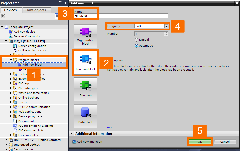
With the data structure defined, the next logical step is to implement this UDT within a Function Block (FB). Go to the "Program Blocks" folder in the "Project Tree" and double-click "Add New Block". In the window that appears, select the "Function Block" tab, name it "FB_Motor", and ensure you choose "Ladder" as the programming language before pressing "OK".
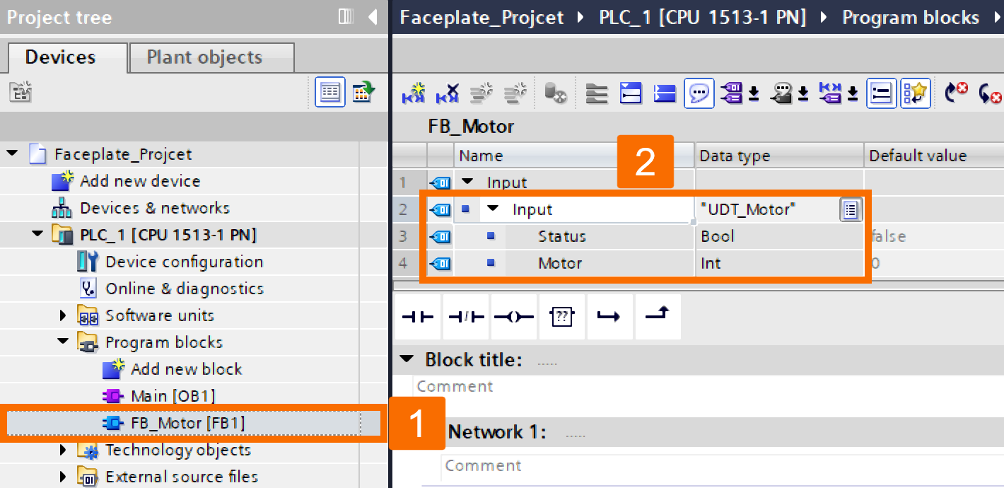
Inside the variable declaration table of this new Function Block, you must define an input variable. Under the "Input" section, create a variable named "Input" and assign it the data type "UDT_Motor" that you created earlier.
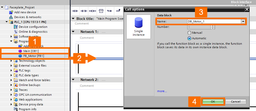
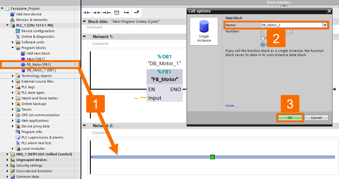
You must now call this Function Block within the main execution cycle. Open the "Main [OB1]" block and drag your newly created "FB_Motor" into "Network 1". When the "Call Options" dialog appears, allowing you to create an instance Data Block, rename this instance to "DB_Motor_1" and click "OK".
Repeat this process for a second motor by dragging the same "FB" into Network 2. When the window appears for this second instance, rename it "DB_Motor_2" and press "OK".
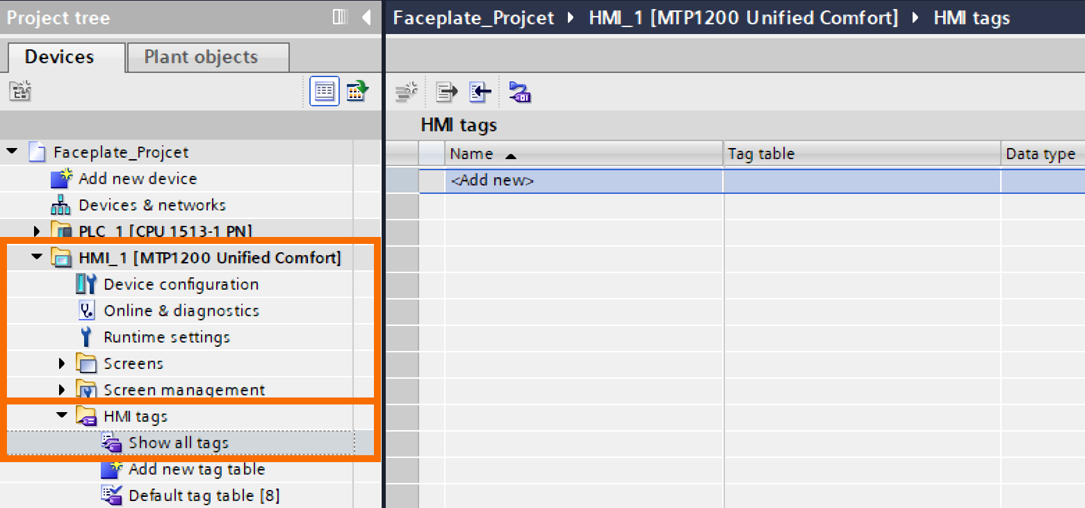
To make these PLC data blocks accessible to the HMI, move them to the HMI tag table, which automatically establishes the connection between the HMI and the PLC. In the "HMI" section of the "Project Tree", expand "HMI Tags" and double-click "Show All Tags".
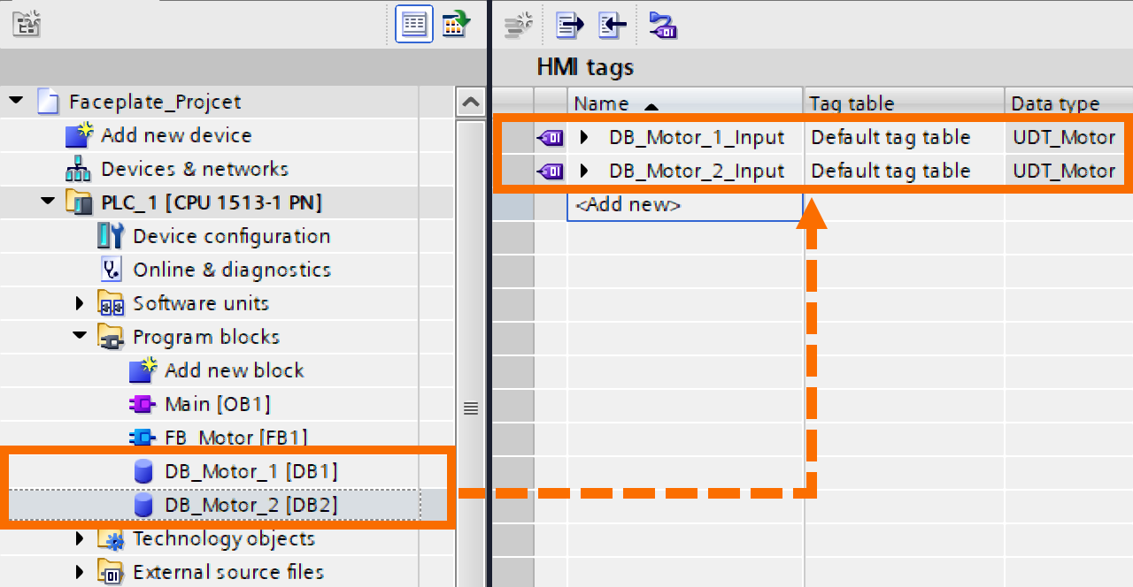
From there, drag "DB1" and "DB2" from the PLC list and drop them into the "HMI Tags" table.
Simple Faceplate Setup
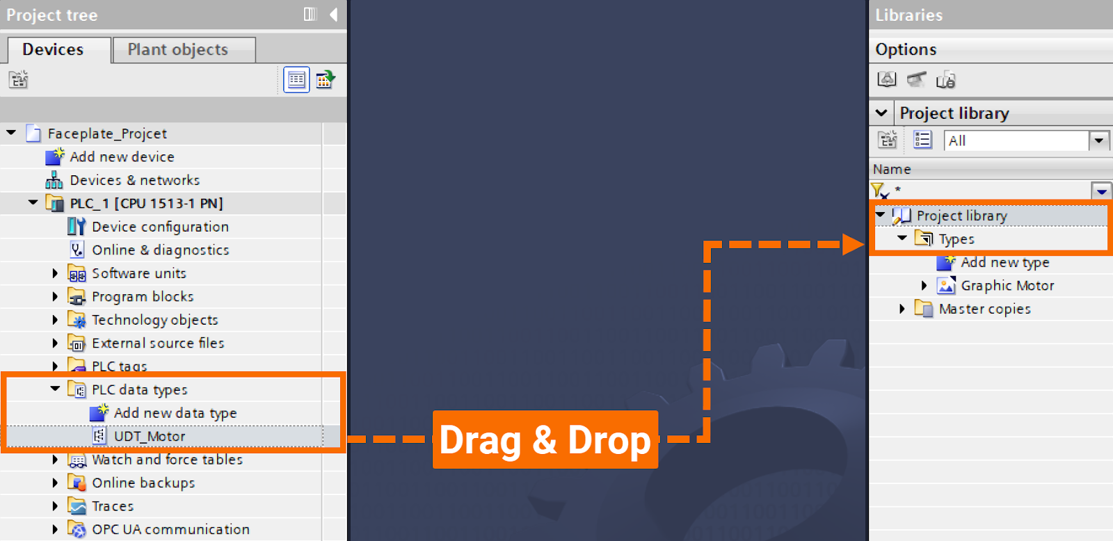
The tutorial now advances to the creation of a basic faceplate. First, you must enable the UDT for use within the library by dragging "UDT_Motor" from the "PLC Data Types" folder and dropping it into the "Types" folder of the "Project Library".
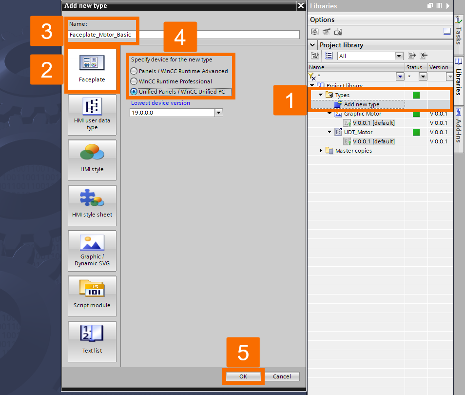
With the UDT available in the library, you can create the faceplate type. Double-click "Add New Type" in the "Types" folder, and in the pop-up window, select the "Faceplate" tab. Name this "Faceplate_Motor_Basic" and ensure you select "Unified Panels/WinCC Unified PC" as the target device technology before clicking "OK".
Faceplate Tag Binding
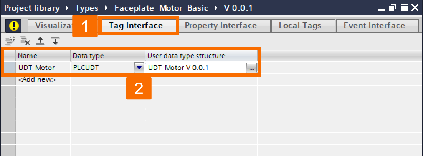
Inside the "Faceplate_Motor_Basic" workspace, you need to bind tags. Open the "Tag Interface" tab to create a connection point for your data. Define a new tag named "UDT_Motor", set its data type to "PLCUDT", and ensure you select the correct version under "User Data Type Structure".
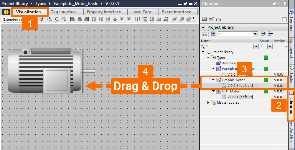
Now, switch to the "Visualization" tab to design the graphical interface. Open the "Libraries" pane and drag the motor graphic you created earlier into the faceplate workspace.
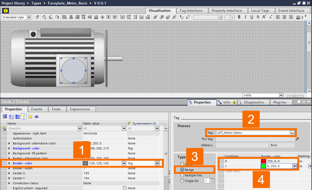
"Toolbox" on the right, drag a circle object and overlay it on the motor graphic. In the "Inspector" window, locate the "Background - Color" property and dynamize it by linking it to the "Status" tag. Configure the range such that a value of 0 displays red and a value of 1 displays green.
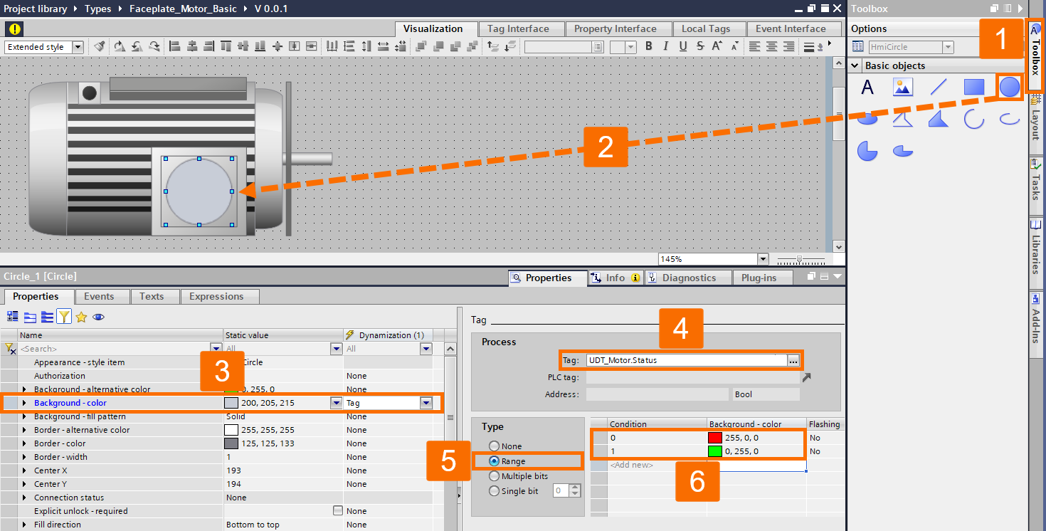
Apply this same dynamization logic to the "Border - Color" of the circle as well.
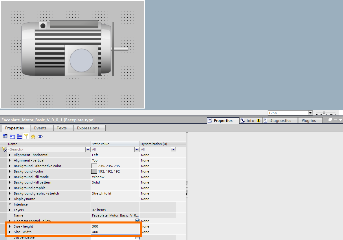
Once the graphics are set, resize the faceplate by clicking the background and adjusting the height and width to perfectly center the motor graphic.
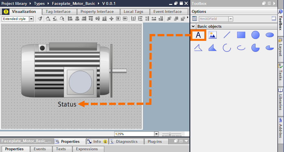
To complete the faceplate functionality, you will add an I/O field linked to the status. Drag a "Text" object below the motor and label it "Status".
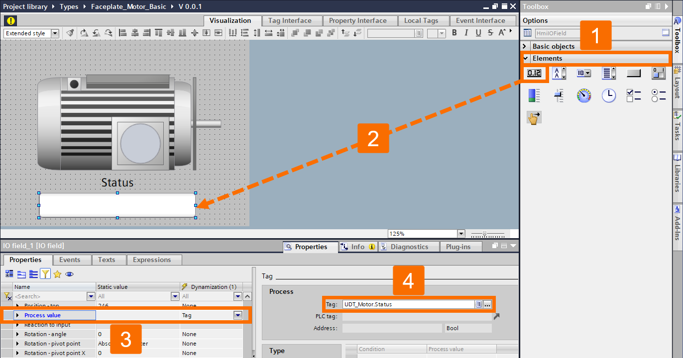
Then, find the "I/O Field" in the "Elements" toolbox and place it beneath the text. In the "Inspector" window, connect the "Process Value" of this I/O field to the "Status" tag.
Finally, release this version of the faceplate by clicking the yellow exclamation mark and selecting "Release the Version", then clicking "OK".
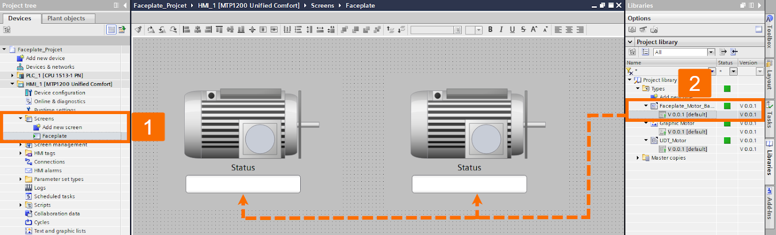
For the implementation phase, navigate to the HMI "Screens" folder in the "Project Tree", create a new screen, and name it "Faceplate". From the "Libraries" tab, drag two instances of "Faceplate_Motor_Basic" onto this screen.
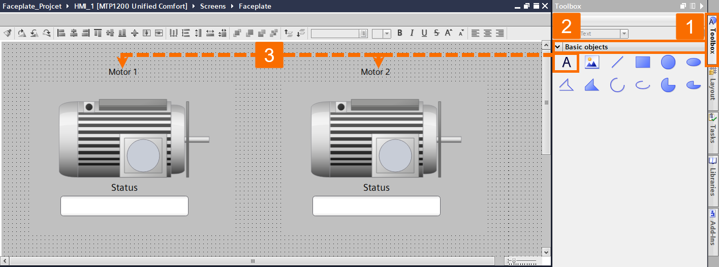
Use the "Toolbox" to add two text labels above the graphics, naming them "Motor 1" and "Motor 2" respectively.
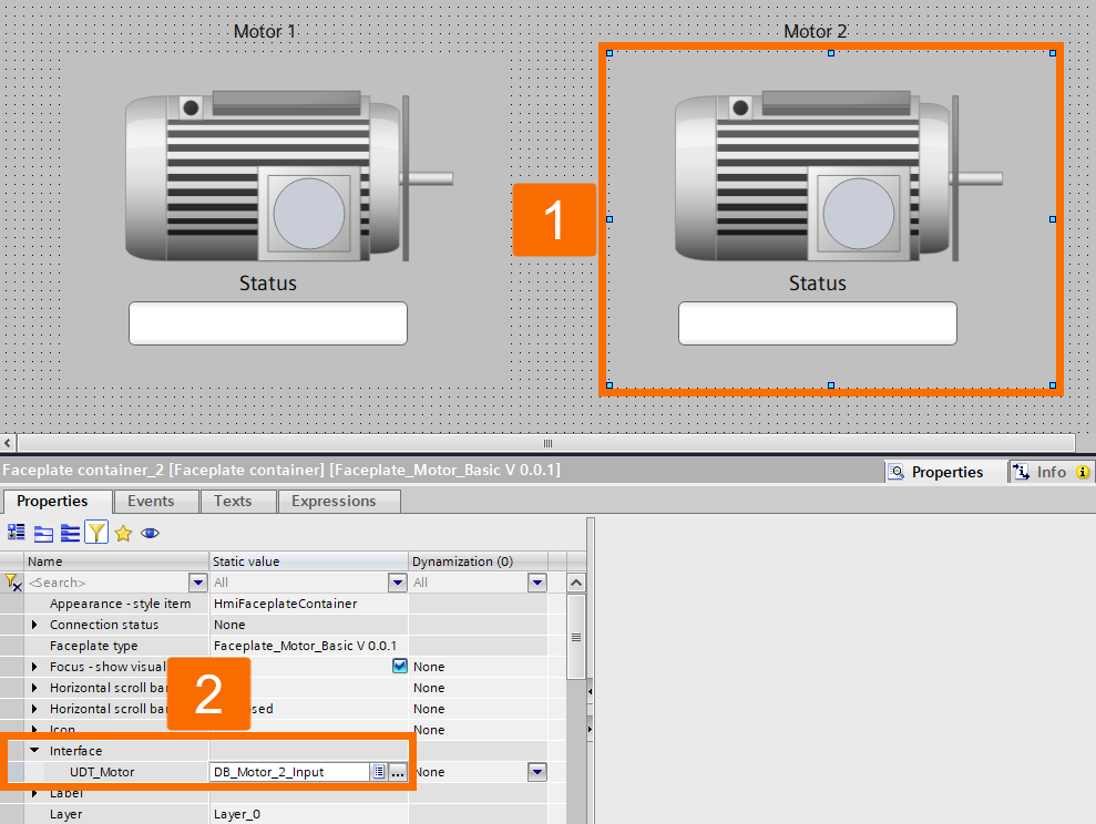
Select the first faceplate instance and, in the "Inspector" window, bind its interface to "DB_Motor_1_Input".
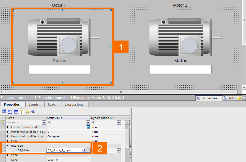
Do the same for the second instance, binding it to "DB_Motor_2_Input".
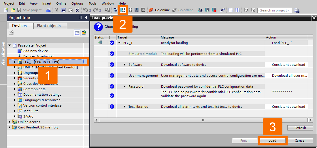
To test the system, highlight the PLC folder and click the "Download" icon in the toolbar. In the "Load Preview", press "Load".
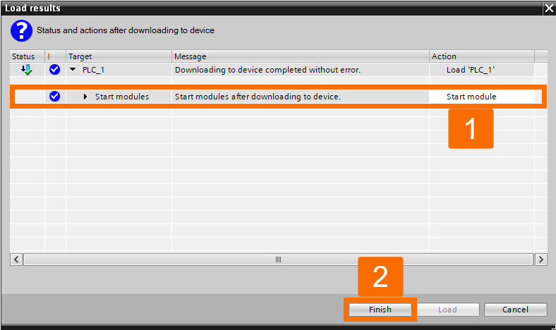
In the subsequent "Load Results" window, select "Start Module" before clicking "Finish".
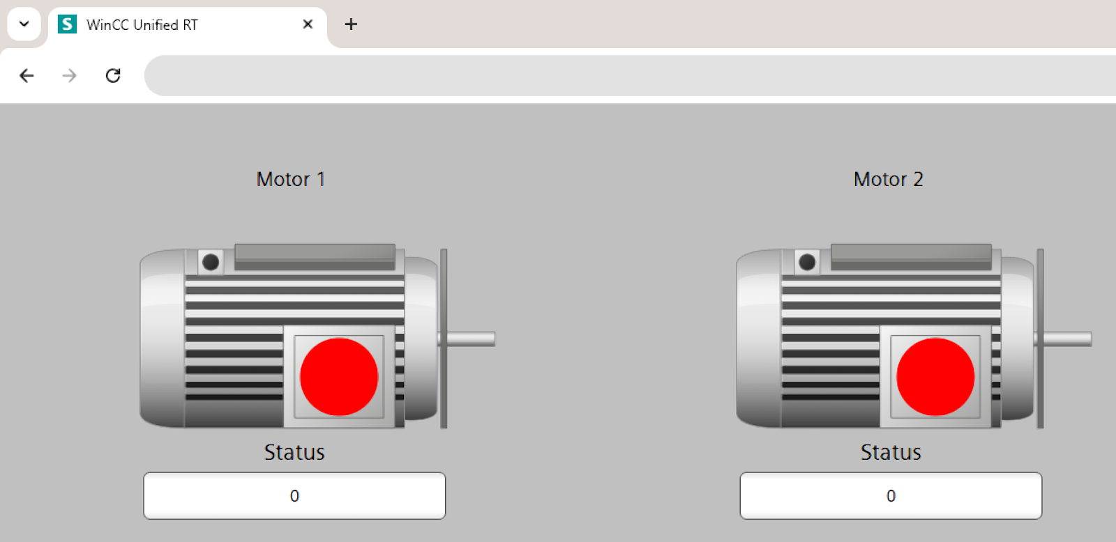
Finally, select the HMI folder and click the "Start Simulation" icon.
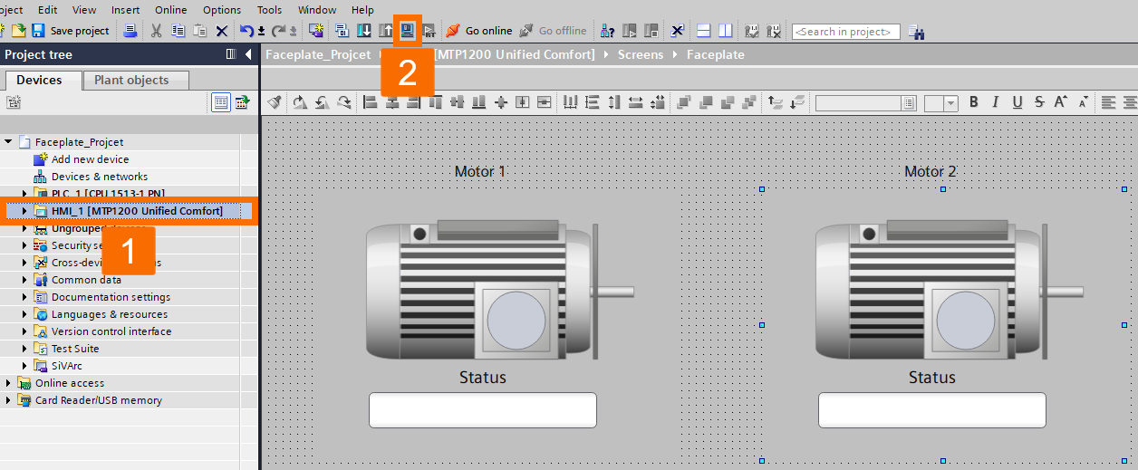
It will launch your default web browser, displaying the active HMI screen with your fully functional motor faceplates.
Conclusion
In conclusion, you learned how to transform a simple static graphic into a powerful, reusable engineering asset. You navigated through the entire development stack, starting from the raw hardware configuration in TIA Portal to defining custom SVG types in the Project Library. You didn't just draw a motor; you structured its data using PLC UDTs and Function Blocks, ensuring a seamless, automatic handshake between the controller and the HMI. By binding these UDTs directly to your faceplate interface, you successfully created a "drag-and-drop" solution that eliminates repetitive tagging. You can now take this exact workflow and apply it to valves, PID controllers, or any other plant asset, proving through your browser simulation that your design is both functional and future-proof.
