Siemens PLCSIM’s New Interface in TIA Portal V18

Introduction
Simulation has become a cornerstone in the industrial landscape, enabling engineers and developers to refine designs, test processes, and troubleshoot without the need for physical prototypes. The ability to emulate real-world scenarios in a controlled environment significantly reduces costs and time-to-market for various industrial projects. In this context, Siemens has unveiled a transformative advancement in its TIA Portal version 18, introducing a revamped interface for PLCSIM. This new interface combines the strengths of PLCSIM Advanced with a fresh, intuitive visual interface.
The latest iteration of Siemens' PLCSIM interface, housed within the TIA Portal v18, marks a substantial advancement in simulation capabilities. Building upon the foundation of the PLCSIM Advanced features, the new interface introduces an intuitive visual layout that simplifies user interactions. This enhanced interface empowers engineers and technicians with an accessible environment to create, configure, and simulate industrial processes. Through this interface, users can design complex simulations and test automation sequences with ease. In addition to its user-friendly nature, the interface now fully supports communication modes, enabling both internal and external communication setups, including TCP/IP over virtual Ethernet adapters.
In this tutorial, you will learn how to leverage the new PLCSIM interface in TIA Portal v18 to simulate industrial automation processes effectively. The tutorial begins with the hardware configuration within the TIA Portal. It then progresses to building a basic program that demonstrates motor control and data transfer functionalities. With the foundation set, the tutorial delves into the heart of the matter – the new PLCSIM interface. You will be guided through the layout, exploring the enhanced project section, the revamped PLC section, and the updated SIM tables and Event tables features.
Prerequisites
To follow this tutorial, you will need an installation of TIA Portal v18 specifically (Including PLCSIM v18). No additional hardware or software is required.
In addition, some basic knowledge about PLCSIM is required. You can refer to An Introduction to Basic Simulations with TIA Portal’s PLCSIM and Using Event Tables and Simulating your HMI with PLCSIM tutorials for more information about the topics covered in this tutorial.
Hardware configuration in TIA Portal
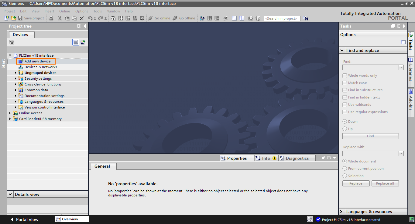
Let’s start by creating a new project on TIA Portal. Once done, click on “Add new device” in the project tree.
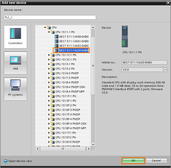
Next, in the “Add new device” window, you can select any 1200 or 1500 CPU of your choice. Here, we will use a 1511-1 PN CPU.
After that, once the station is created, select a DI/DQ module and drag it to the second rack slot.
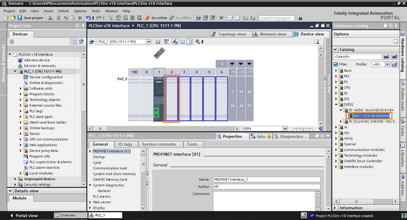
This will add the DI/DQ module to the station. This module will be relevant later in the tutorial during the simulation part.

Creating a small program in TIA Portal
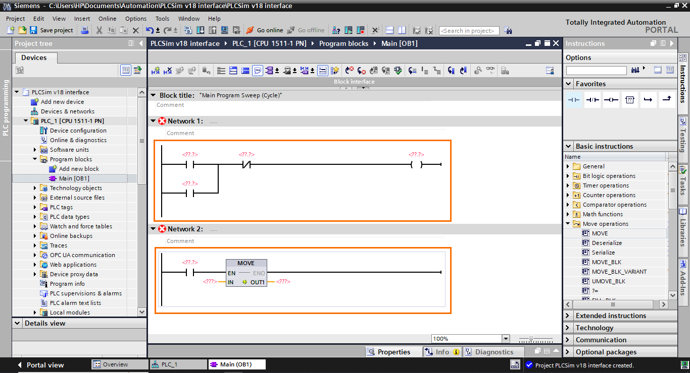
In order to illustrate how the new interface of PLCSIM works, we will use two simple programs; The first will be basic motor control. The second will be a data transfer application controlled by a boolean. Open the main program (OB1) in the program blocks section of the project tree.

The first step is to build the program. Reproduce the programs shown in the following figure.
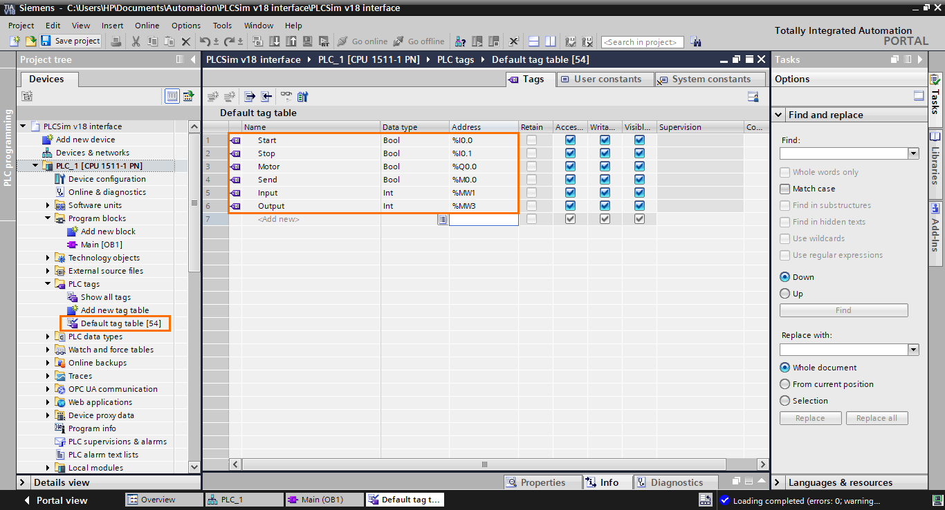
Next, open the default tag table in the project tree and create the following tags. Be sure to define the correct data types.
Then, add the tags to the program, as shown in the following figure.
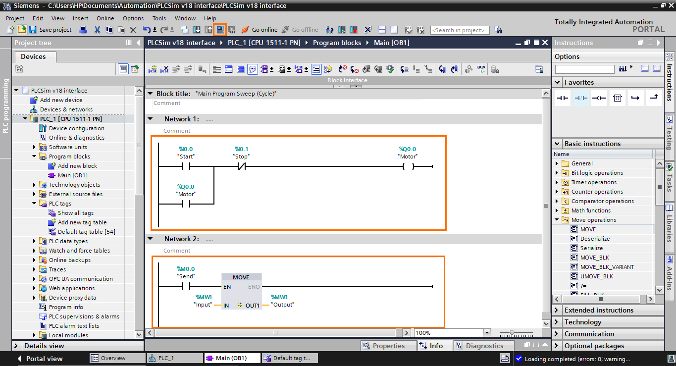
The program in Network 1 is a simple start/stop application to control a motor. When the “Start” tag is set to 1, it will turn on the motor. The parallel “Motor” NO contact is used to hold the motor turned on even if the “Start” tag resets to 0. And if the “Stop” NC contact is set to 1, it will disable the motor.
In Network 2, we use a NO contact to control the “MOVE” instruction. If the “Send” tag is set to 1, the data stored in the “Input” tag will be transferred to the “Output” tag.
PLCSIM’s new interface overview
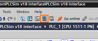
We are done configuring and programming in the TIA Portal project; we can head to the PLCSIM side. Open PLCSIM by either starting from your desktop or the start menu. Or by clicking on the “Start simulation” button (Small blue computer icon).
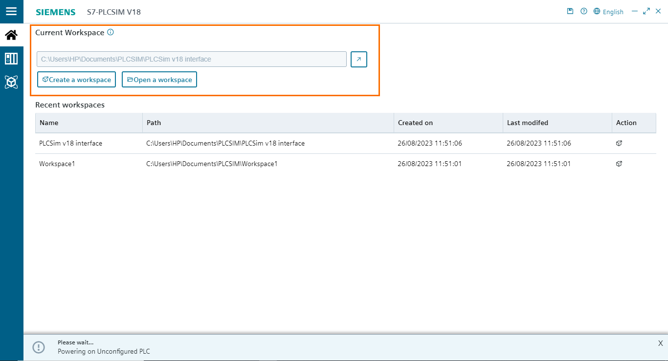
This will open PLCSIM’s interface. If you are used to the old interface, you may be a little lost at first. The first thing to notice is that there is no longer a compact view. PLCSIM now works only in project view mode. Next, the first page you arrive at is the project section. Here, you can create or open PLCSIM projects renamed workspaces. By default, a workspace is automatically created for your current TIA Portal project upon opening PLCSIM.
Next is the PLC section. It is a new section where you can create PLC instances like you would do in PLCSIM Advanced.
- You can define the communication mode (PLCSIM internal softbus or TCP/IP over a single or multiple virtual ethernet adapters). This feature requires a PLCSim Advanced license.
- You can select which CPU type to simulate in the Library section. By clicking on a plus icon button, it will add a new instance using the selected CPU type.
- All instances are displayed in a box where you can interact with it. You can turn the instance on or off with the On/Off button. The instance’s name, IP address, and state are displayed in the middle of the box. You can switch the CPU to run or stop mode using the play and stop buttons at the bottom of the box.
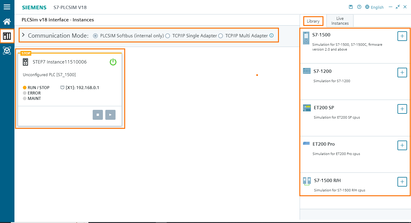
For the moment, we have not injected any program into the virtual PLC yet. Therefore, the virtual CPU is in stop mode. In order to load the program into the CPU, click on the “Load into device” button while PLCSIM is opened. Once on the “Load preview” window, click on “Load”.
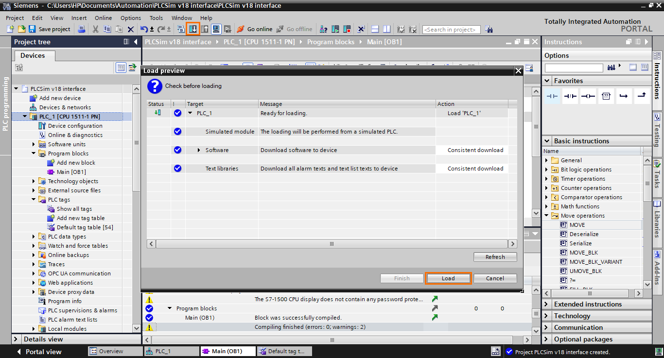
After that, in the “Load results” window, select “Start module” and then click on “Finish”.

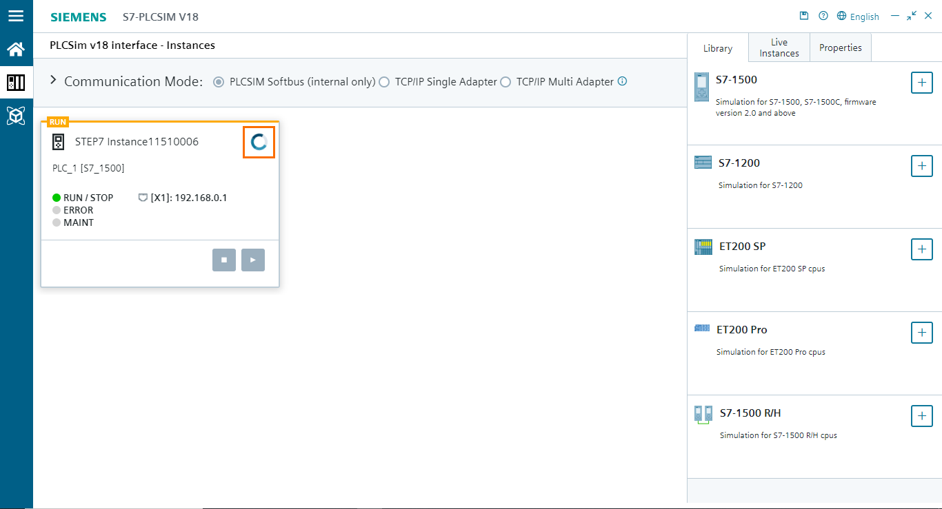
Now, go back to PLCSIM. You should find that the instance is in loading mode. Wait for the loading to finish; depending on your PC’s performance, it may take some time.
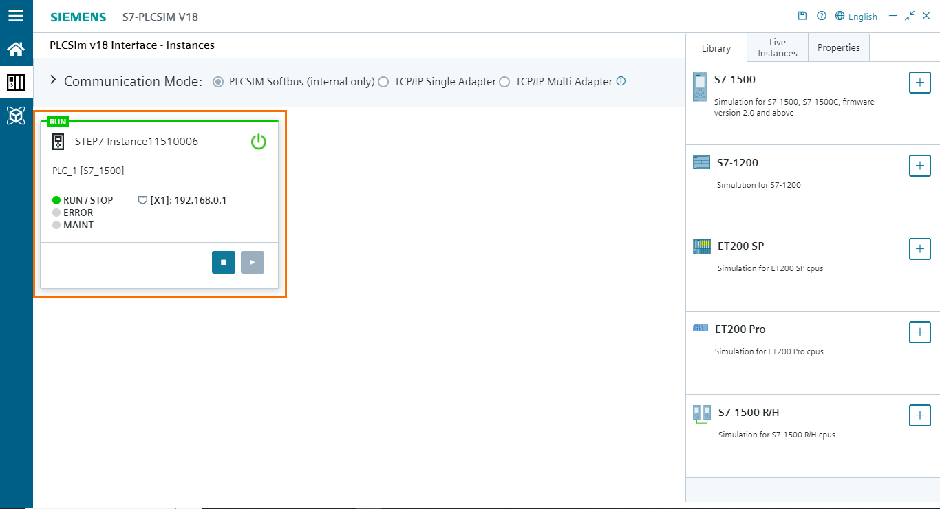
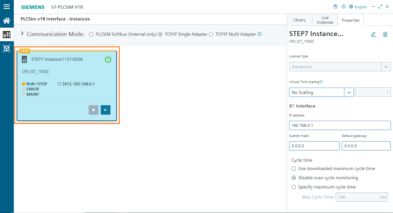
Once the loading is done, it will be indicated in the instance box with the green border on the top and the On/Off button turning back to normal. The program is now being executed in PLCSIM’s virtual PLC.
PLCSim Advanced features
With this new version of PLCSIM, it is now possible to interact with PLCSIM Advanced instances directly from the regular PLCSIM interface. For this, a PLCSIM Advanced license is required. This feature allows you to create new Advanced instances, edit previous instances, turn a regular instance into an Advanced instance, and use TCP/IP communications all from the new PlCSIM interface
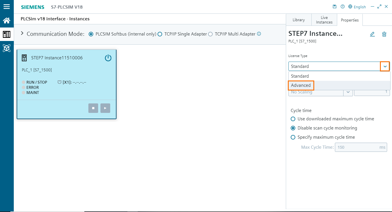
Let’s have a look at how it works. We will turn this instance into an Advanced instance. Please note that this also applies to newly created instances in cases where you want to create an Advanced instance directly in PLCSIM. First, open the properties tab of the instance. You will find a “License Type” section that cannot be modified. We need to disable the instance beforehand. Click on the instance’s power button to disable it.

Once done, the “License Type” section becomes available.

After that, open the licenses list by clicking on the arrow button. then, select “Advanced.”
Since the instance uses now an Advanced license, we can enable the TCP/IP communication. Click on the “TCP/IP Single Adapter” option and turn on the instance.
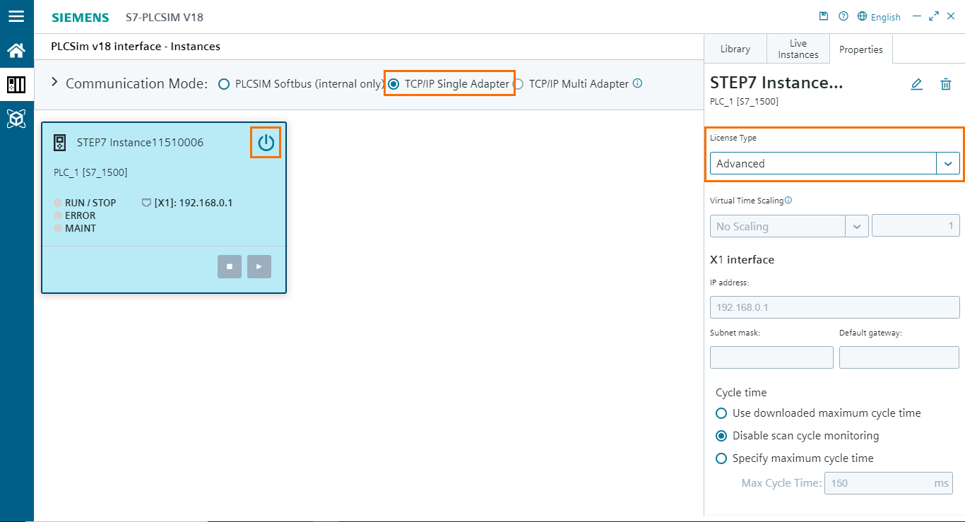
And we are done. We have turned this regular instance into a PLCSIM Advanced instance.
If you open the PLCSIM workspace, you will find this instance displayed in the instances list.
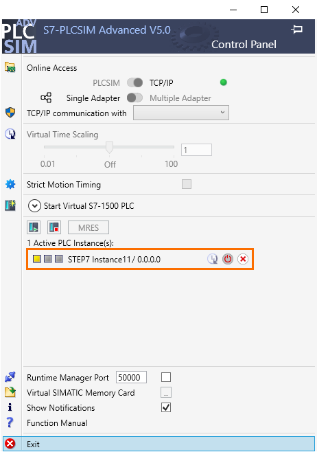
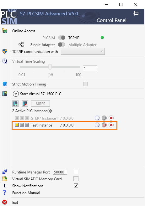
It is also possible to create an instance in PLCSIM Advanced directly and display it in the regular PLCSIM. Create an instance in PLCSIM Advanced. You can refer to the PLCSIM Advanced tutorial to see how it is done.
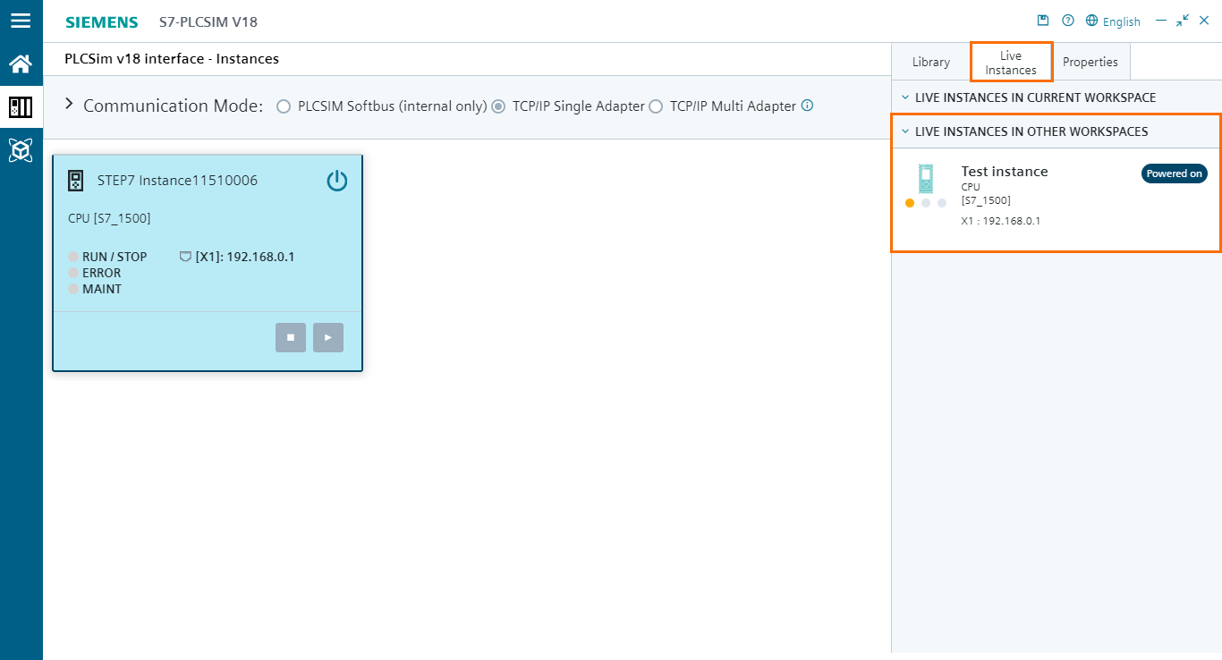
Then, go back to PLCSIM and open the “Live Instances” tab. You will find this instance displayed in the “Live Instances In Other Workspaces” section.
SIM tables’ new interface
The next section of the new PLCSIM interface is the simulation section. Here, you can create SIM tables and Event tables. These features were already present in the previous interface (In project view mode), SIM tables allow you to interact with tags and DB elements of the PLC program, and Event tables allow you to trigger different types of PLC events, such as hardware interrupts, diagnostic error interrupts, pull/plug of modules, and rack or station failures. You can find more details about how these features work in An Introduction to Basic Simulations with TIA Portal’s PLCSIM and Using Event Tables and Simulating your HMI with PLCSIM tutorials.
We can also notice the absence of sequences in this new version of PLCSIM, which will be available in the upcoming updates.
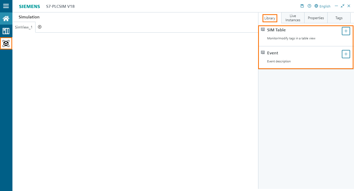
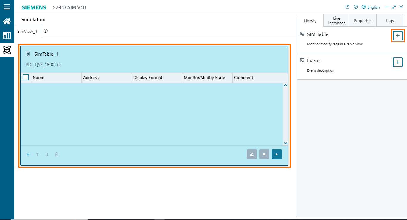
Let’s first take a look at SIM tables. Click on the plus button in the SIM table section of the library tab. This will add a new SIM table in the workspace. In this table, you can add tags and DB elements to monitor and modify their state/value.
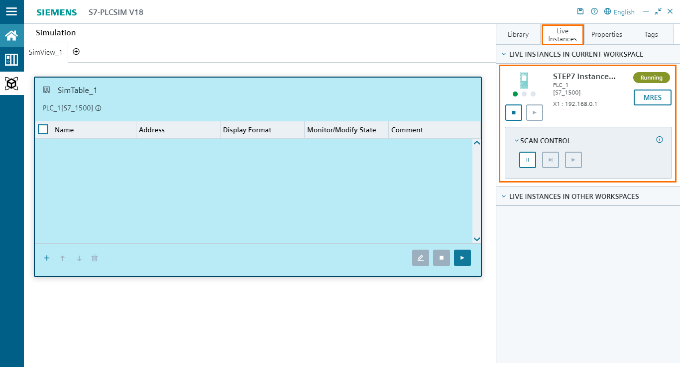
You have access to various tabs beside the library. The “Live instances” tab allows you to interact with the CPU while performing simulations without having to return to the PLC section.
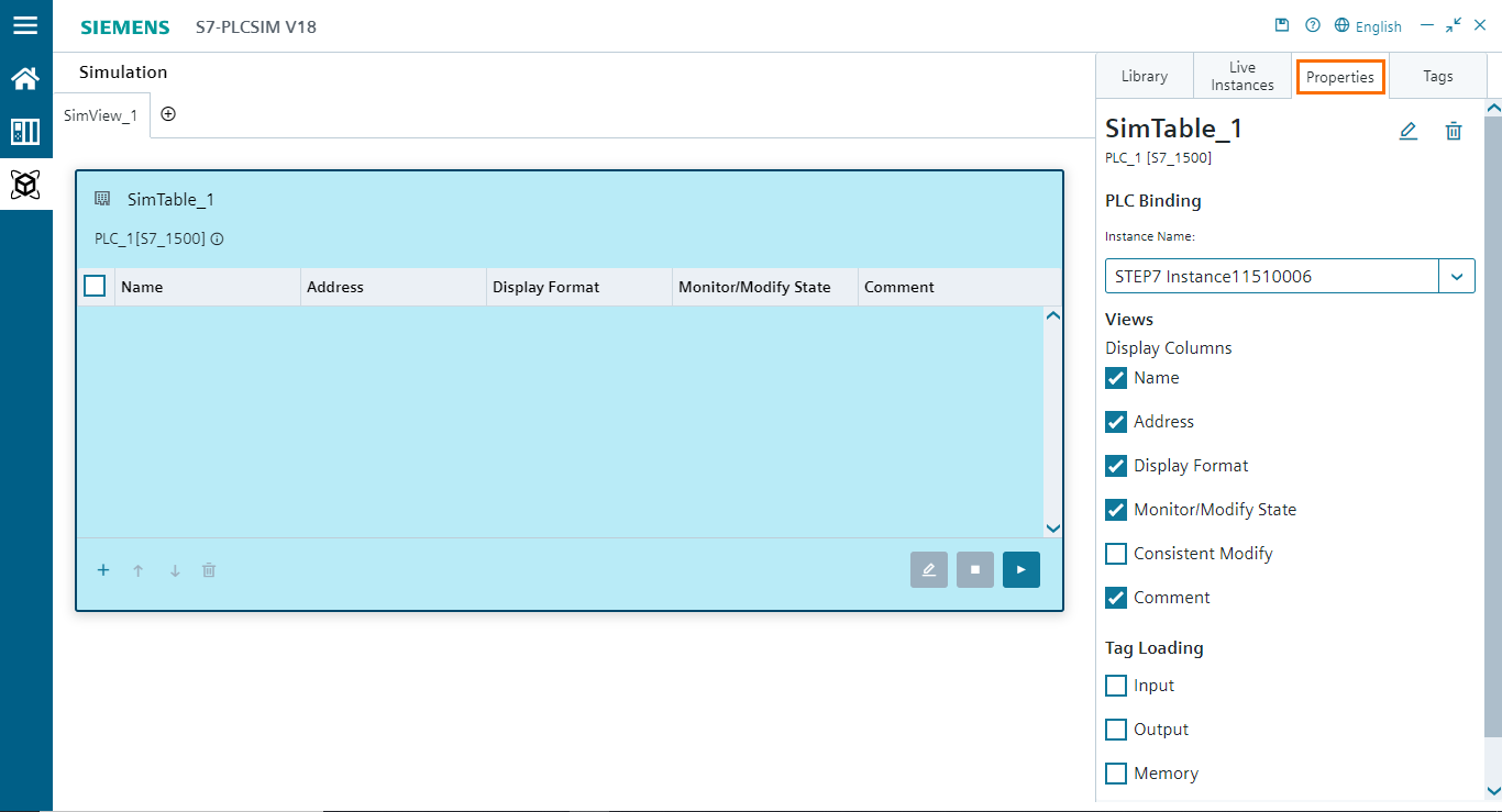
In the “Properties” tab, you can define the properties of the selected element. In this case, it is the SIM table that is selected. So, you have access to the SIM table properties, such as the used instance, displayed columns, and loaded tags.
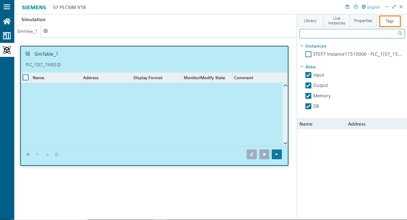
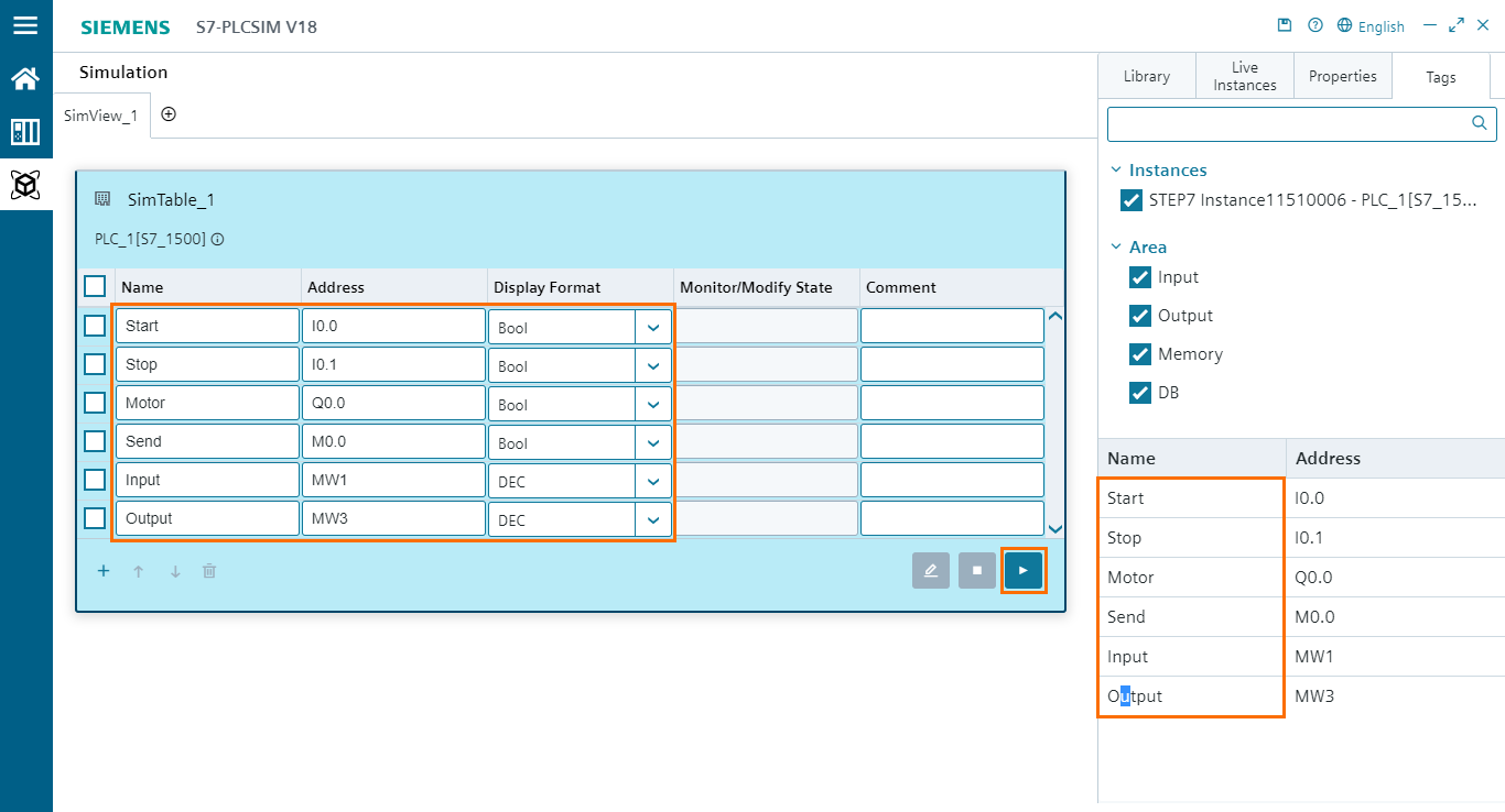
The last available tab is the “Tags” tab. Here, you can select which tags or DB elements to add to the SIM table. For this, you have to find an instance in the “Instances” section and select which type of tags (inputs, outputs, memories, and DB elements) to load.
By selecting an instance, all the tags present in the project loaded in this instance will become available in the list below.
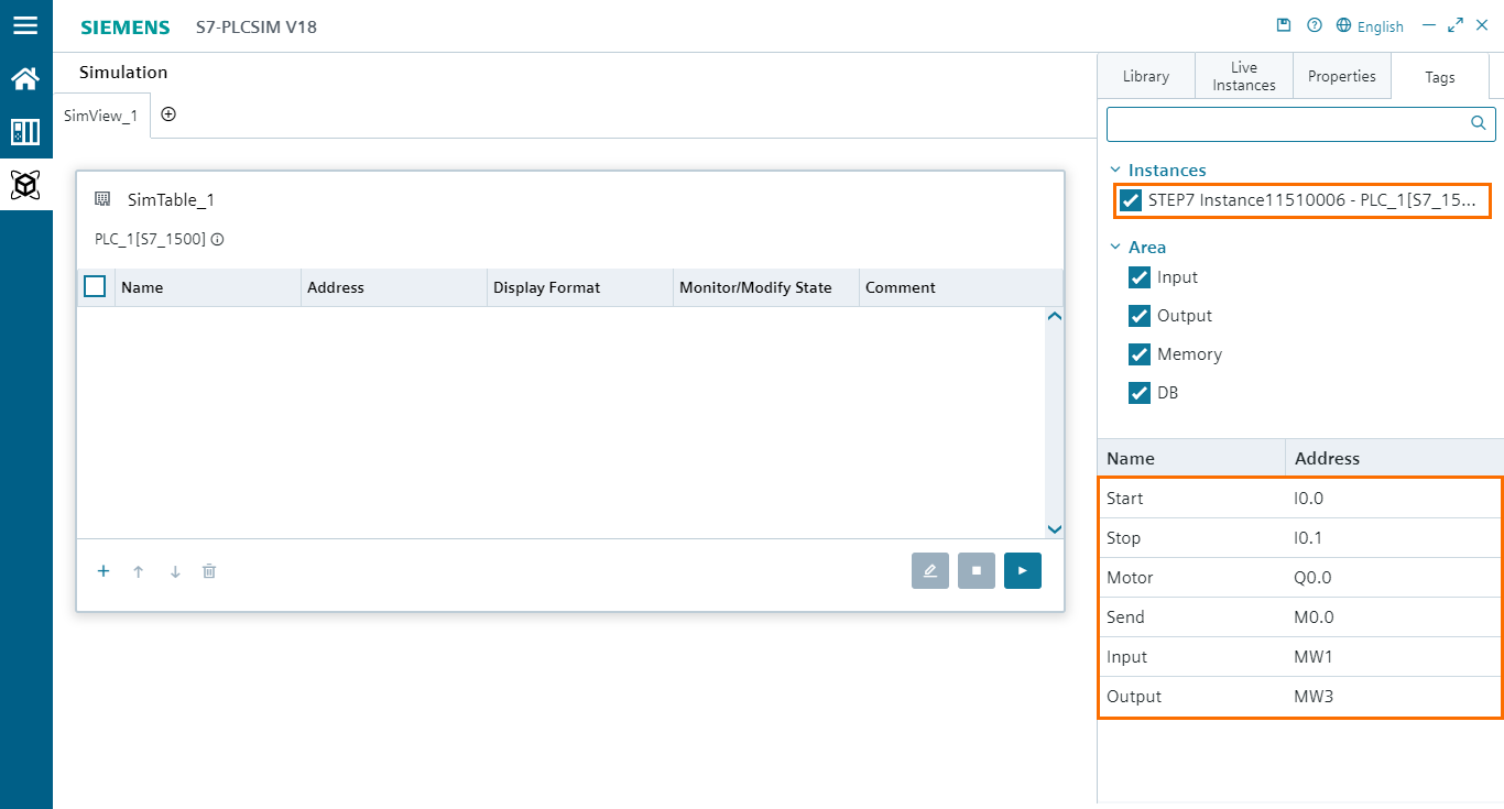
To add tags to the SIM table, simply click on them in the tags list.
Once the tags have been added to the table, you can click on the blue “Play” button to start running the monitoring of the tags. This will display the current value of the tags in the “Monitor/Modify State” column. You can also stop the monitoring by clicking on the blue “Stop” button.
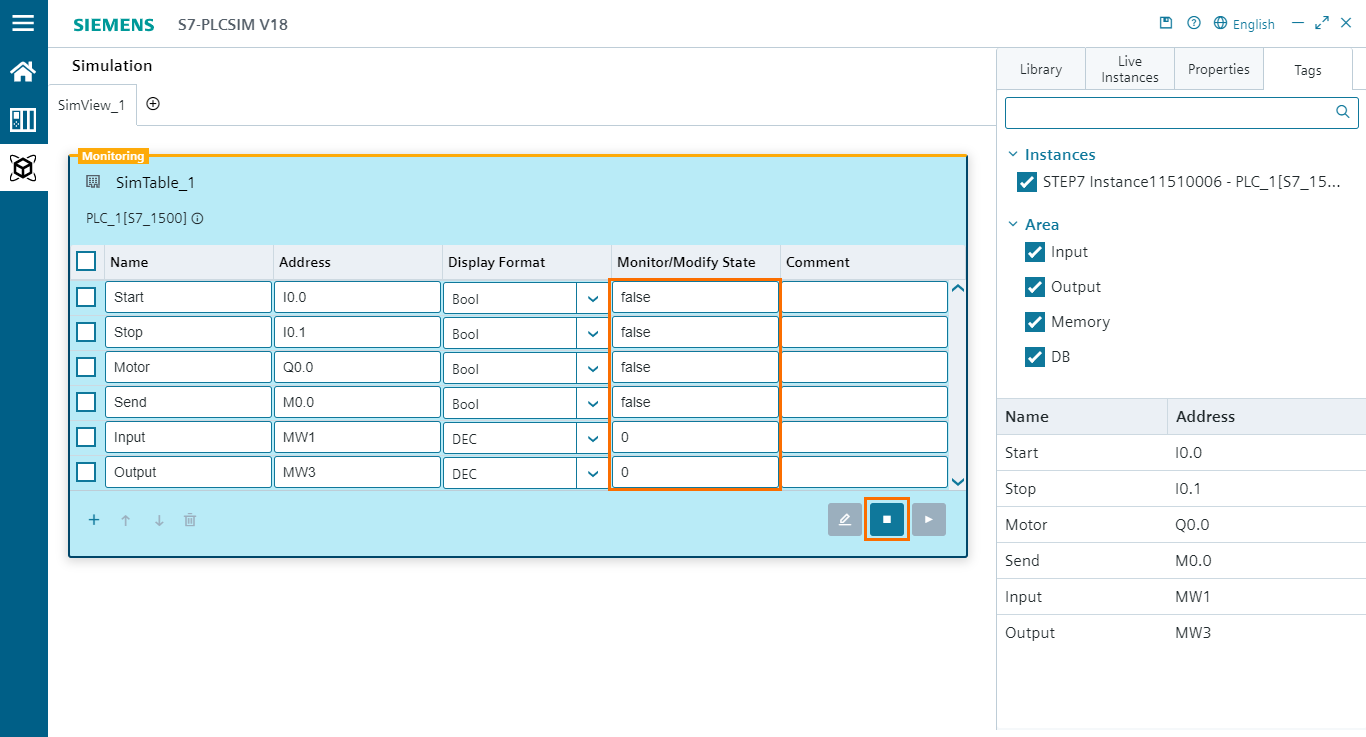
While monitoring is active, you can modify the value or state of a tag by typing the value you want to change in the “Monitor/Modify State” column, as shown in the following figure.
As you can see, modifying the value/state of tags does induce the right response from the program. We are able to start and stop the motor and transfer data correctly.
Event tables’ new interface
Let’s head now to the second feature of PLCSIM’s new interface, the Event tables. We need first to add a new simulation page where we will add the Event table. To do this, click on the small white plus button on the workspace. This will add a new page called SimView_2 (SimView_1 being the page where we added the SIM table).
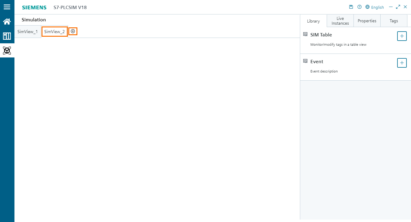
Next, to add an Event table, click on the blue plus button in the “Event” section of the library. This will add an Event table box in the workspace.
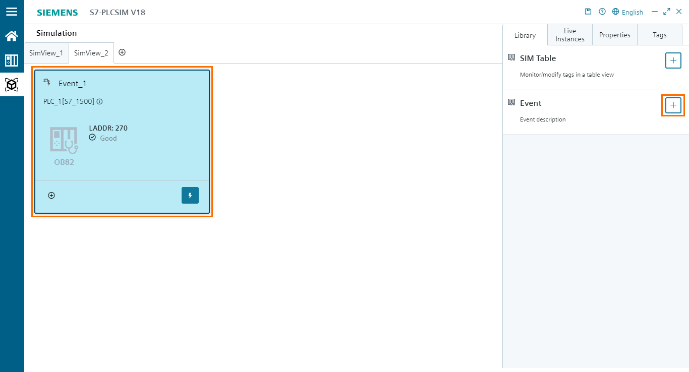
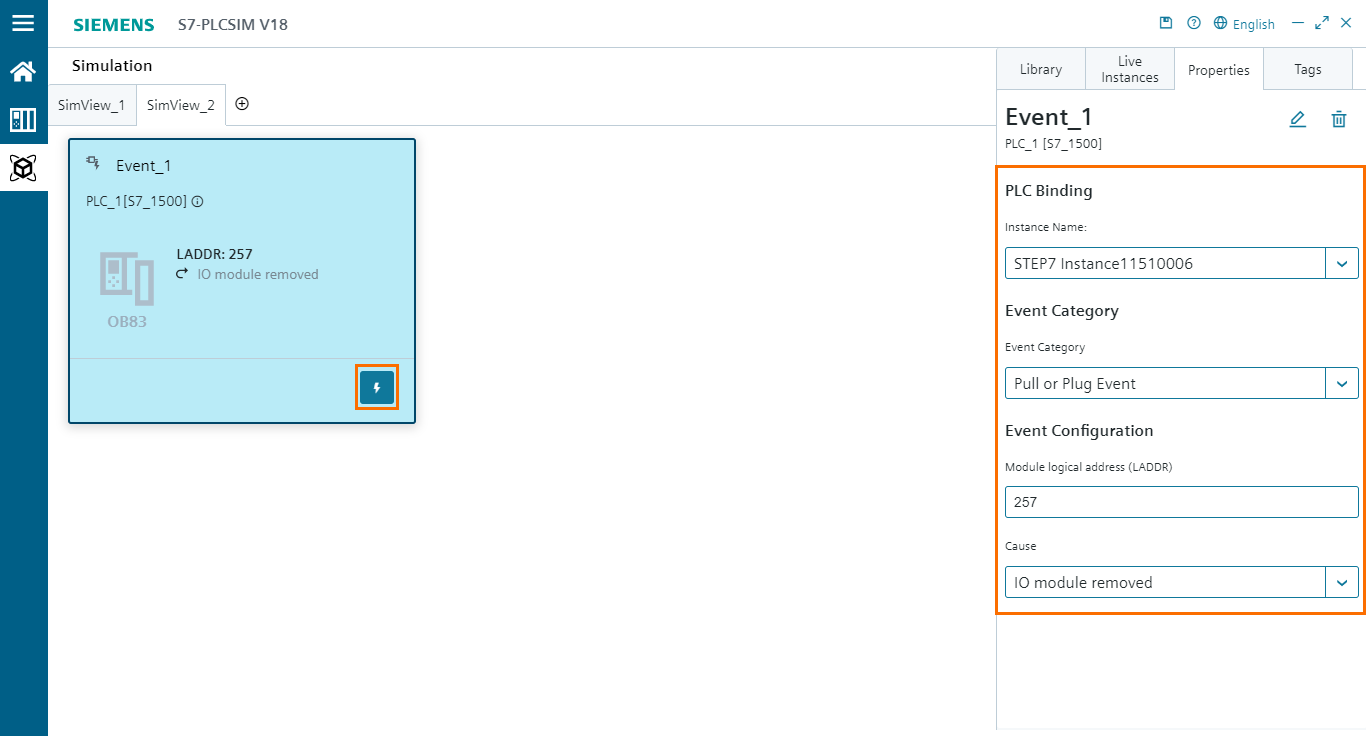
After that, we need to configure the Event table. Open the “Properties” tab (While the Event table is selected). Here, you will find all the properties of the Event table such as the used instance, the event category, the hardware address of the module, and a section that depends on the selected event category.

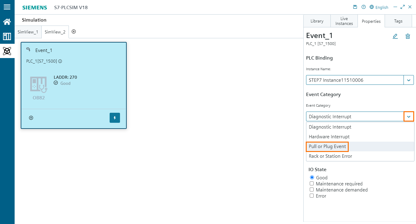
The Event category section allows you to select the type of event you want to trigger (Diagnostic interrupt, Hardware interrupt, Pull or Plug Event, and Rack or Station Error). For this example, we will try to trigger a “Pull or Plug Event” of the DI/DQ module we configured previously. Open the Event category list and select “Pull or Plug Event”.
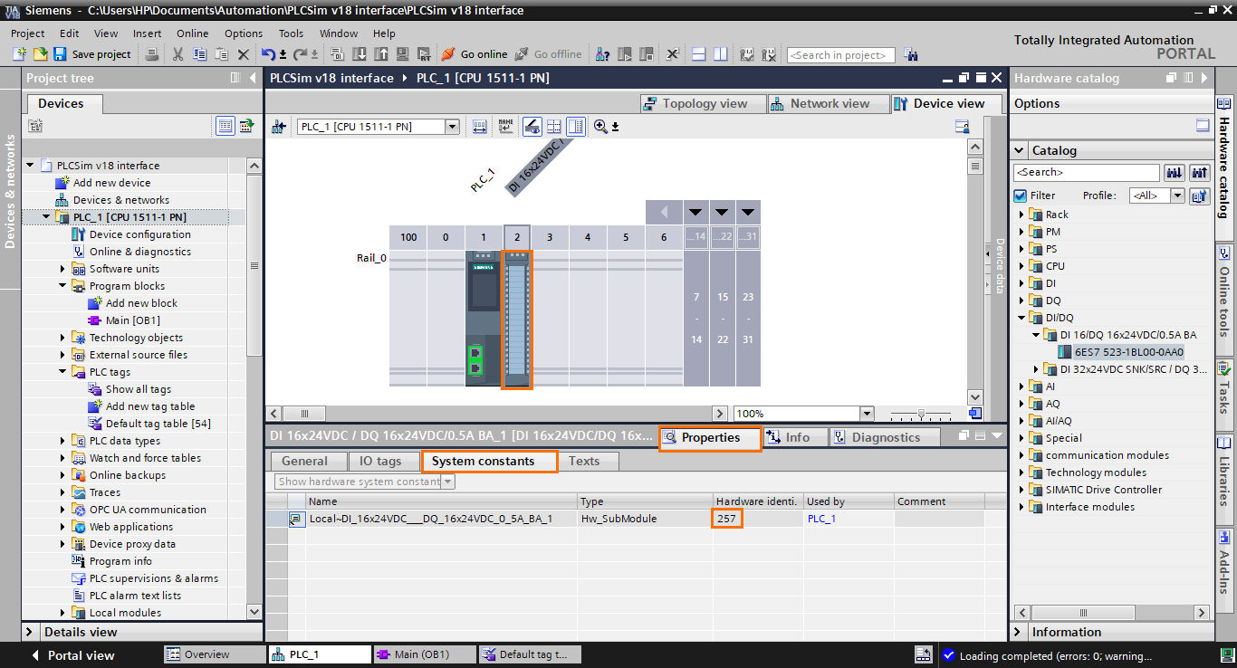
Once done, we need to specify the hardware address of the DI/DQ module. You can find this address in the “System constants” tab of the DI/DQ module’s properties. In our case, the address is “257”.
After retrieving the hardware address, add it to the “Module logical address (LADDR)” section of the Event table properties.
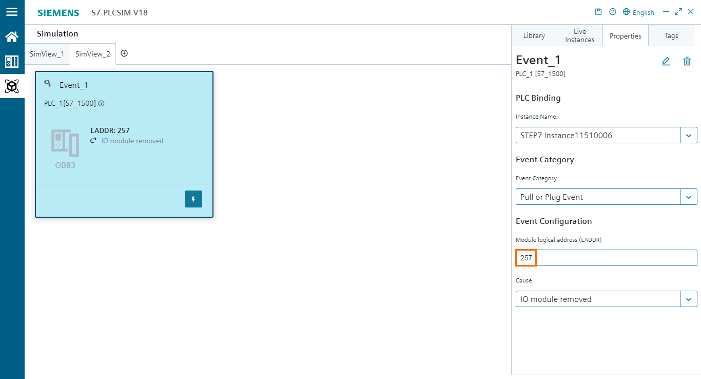
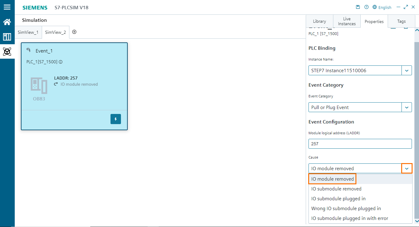
The last thing we need to configure is the Event cause, where we define the type of Event that will occur, such as “IO module removed,” “IO submodule removed, “Wrong IO submodule plugged in”...etc. Here, we will select the “IO module removed” event.
With this, the Event is configured completely. To trigger it, click on the lightning-shaped button in the Event table box.
You can check if the event has been triggered correctly in the diagnostic buffer of the CPU, as shown in the following figure.
Triggering the event causes an error to appear on the CPU indicated by the message "Hardware component removed or missing" and the red error LED in the CPU interface.
Conclusion
In this tutorial, you learned how to effectively harness the capabilities of the new PLCSIM interface in TIA Portal v18. Beginning with hardware configuration, you gained insights into creating projects, selecting CPU types, and integrating modules for simulation. Moving forward, you delved into program creation, exemplifying motor control and data transfer functionalities. The heart of the tutorial explored the revamped PLCSIM interface, providing a comprehensive walkthrough of the project, PLC, SIM tables, and Event tables sections.
Incorporating Siemens' new PLCSIM interface into the TIA Portal v18 has significantly elevated the user experience when working with simulated PLCs. The intuitive layout and comprehensive design of the interface streamline the creation, configuration, and execution of simulation scenarios. With a user-friendly approach, engineers and technicians can efficiently test and validate automation processes, making informed decisions for real-world applications. The integration of PLCSIM Advanced features and the introduction of novel functionalities, coupled with the enhanced visual interface, mark a substantial stride toward facilitating more intuitive and effective industrial simulation within the TIA Portal v18 environment.
